Table of Contents
Advertisement
Advertisement
Table of Contents

Summary of Contents for Unilock U-Cara
- Page 1 MODULAR FIREPLACE SYSTEM US PATENT: 9,453,341 INTERNATIONAL PATENTS PENDING...
- Page 2 MODULAR FIREPLACE SYSTEM This truly revolutionary U-Cara Modular Fireplace is easily constructed in one day with only a handful of basic tools. The ability to mix and match several panel color and/or textures allows you to be creative while maintaining...
-
Page 3: Table Of Contents
BUILDING AND FIRE CODES BEFORE PURCHASING. Standard Chimney Components ......34 - 35 Firepan Assembly ............Unilock is not responsible for Backer Block Adjustable Base ........Heatshield Assembly (Counter top Model) ..... any violation of local codes. Cabinet and Backer Block Base Connection .... -
Page 4: 42" Fireplace (Woodburning)
UL-FIR 42" Fireplace Woodburning CABINET COMPONENTS MUST BE BUILT WITH OVERSIZED WIDTH COMPONENTS 36 3/4'' 83’’ DIMENSIONS WITH FASCIA PANEL 41 3/4” x 88” (Outside To Outside) WEIGHT Without endclads = 115 lbs With ECK-OS = 161 lbs (Oversized width) UL-FIR-FP ........ - Page 5 42" Fire Cabinet Woodburning CABINET COMPONENTS (CONTINUED) ULHAR ..........Horizontal Adjustable Rail NOTE: Always use included lock washer with 9/16" bolt connection on each corner (8 total). CLAMPS MAY BE USED TO SECURELY HOLD STRUTS IN PLACE WHILE CONNECTING Braces are attached via Connect with tab and a self-tapping self-tapping screw...
- Page 6 UL-FIR-MW 42" Fireplace Woodburning MANTLE COMPONENTS OVERSIZED WIDTH COMPONENTS 27 1/5'' 83’’ 83" 80" DIMENSIONS WITH FASCIA PANEL 32 1/2” x 88” x 12” (Outside To Outside) UL-FIR-M-BP Back ......Elevation View WEIGHT Base Module Front Panel 68 lbs Plan View 27 1/2’’...
- Page 7 42" Fire Cabinet Woodburning MANTLE COMPONENTS (CONTINUED) NOTE: When assembling ensure all rail angles are directing upward. NOTE: Refer to page 24 for Fireplace assembly sequence.
- Page 8 UL-FIR-CHW 42" Fireplace Woodburning 36 3/4'' CHIMNEY COMPONENTS Left Front Elevation Elevation View View OVERSIZED WIDTH COMPONENTS 11/16" 11/16" 36-3/4" DIMENSIONS WITH FASCIA PANEL 32 1/2” x 41 3/4” (Outside To Outside) Plan View WEIGHT 65 lbs UL-CCBP-OS 2 PC 27 1/2'' ......
- Page 9 42" Fire Cabinet Woodburning CHIMNEY COMPONENTS (CONTINUED) NOTE: Refer to page 28 for Fireplace assembly sequence.
- Page 10 UL-FIR-RTN-OS 42" Fireplace Woodburning OVERSIZED RETURN PANEL 36 1/2" UL-FIR-LFT-OS 1 PC ....Left Return Panel 36 1/2" NOTE: Ensure return panels are positioned in the correct orientation (right and left). MUST BE BUILT WITH Rails should be facing inward OVERSIZED WIDTH UL-FIR-RTN-OS 1 PC...
-
Page 11: Oversized End-Clad
UL-ECK-OS 42" Fireplace Woodburning OVERSIZED END-CLAD 32 ¾" UL-ECP-OS ......... End Clad Panel Oversized NOTE: Remove connecting struts and replace with end-clad panel using existing hardware. -
Page 12: Modular System Base
Modular System Base TYPICAL COUNTER TOP U-CARA MODULAR FRAME U-CARA FASCIA PANEL RECOMMENDED: 1/4" - 3/16" ANCHOR BOLT ADHESIVE UNILOCK PAVER ASTM#8 OPEN-GRADED SETTING BED ASTM#57 OPEN-GRADED GRANULAR BASE SUBGRADE SOIL SONOTUBE... -
Page 13: Backer Block Components
42" Fireplace BACKER BLOCK COMPONENTS STANDARD BACKER BLOCK CORNER BACKER BLOCK LARGE BACKER BLOCK UNIVERSAL BASE UNIT SURE TRACK CORNER INSERT 6" H x 8" L x 6" W 6" H x 7" L x 12" W 6" H x 7" L x 12" W 2"... -
Page 14: Backer Block Adjustable Base
42" Fireplace Woodburning BACKER BLOCK ADJUSTABLE BASE NOTE: This should be constructed on USED TO PROVIDE CORRECT top of poured in FIREPLACE INSERT HEIGHT place concrete pad (similar to 2ND/TOP ROW ONLY: STANDARD BACKERS page 12). ALLOW FIREPLACE INSERT TO FIT WITHOUT HAVING TO CUT LARGE BACKERS FINISHED DIMENSIONS 88”... - Page 15 42" Fire Cabinet Woodburning BACKER BLOCK ADJUSTABLE BASE (CONTINUED) NOTE: This layout includes a hearth. If no hearth is desired, width can be shortened by 9 1/4" to be flush with cabinet.
-
Page 16: Assembly
42" Fireplace Woodburning ASSEMBLY NOTE: Place 3-sided assembly on Backer Base - Using 1/4"- 3/8" Concrete anchors (not included) connect cabinet to Backers. NOTE: Prior to attaching cabinet top, lugs will need to be removed with a hammer and chisel ENSURE UNIT IS (top row of block only). - Page 17 42" Fire Cabinet Woodburning ASSEMBLY (CONTINUED) NOTE: Center Fireplace NOTE: Cabinet in Backer Ensure to align with back row of Block cavity. Standard backer. This will ensure proper flue alignment with mantle.
- Page 18 42" Fire Cabinet Woodburning ASSEMBLY (CONTINUED) NOTE: Slide (tuck) Returns under the top and bottom angle struts. RAILS SHOULD FACE INWARD AND UPWARD SHOULD FACE FRONT OF FIREPLACE CABINET NOTE: Return Panels have a Right and Left unit. They should be positioned on either side of the firebox flange/edge.
- Page 19 42" Fire Cabinet Woodburning ASSEMBLY (CONTINUED) NOTE: Use a clamp to keep returns aligned to desired plumb and level position while Use included attaching self-tapping ST02 self-tapping screws. screws to connect return panels. PAGE NOTE: REV BY: NM OF 19 1-855-906-3858 The screw position under the SALES@GRILLNETICS.COM...
- Page 20 42" Fire Cabinet Woodburning ASSEMBLY (CONTINUED) REPEAT PREVIOUS UL-FIREPLACE-OS_INSTRUCTIONS PROCESS FROM LW01 BACK SIDE ON PAGE 19 ST01 NOTE: Use a clamp to keep returns aligned to desired plumb and level position while attaching self-tapping screws. Use included ST02 self-tapping screws to connect return panels.
- Page 21 42" Fire Cabinet Woodburning ASSEMBLY (CONTINUED) CUT WILL VARY BY FIREBOX INSERT DIMENSION NOTE: Cut will start at the edge of each interior Return panel. Center Strut will also be cut as well as bottom rail.
- Page 22 42" Fire Cabinet Woodburning ASSEMBLY (CONTINUED) NOTE: Adjust HAR on both sides of the flue pipe to help keep it aligned. These will be tucked under the top angle rail. NOTE: Snap 18" Flue pipe into insert.
- Page 23 42" Fire Cabinet Woodburning ASSEMBLY (CONTINUED) NOTE: Clamp and attach using ST02 self-tapping screws. Repeat process on backside.
-
Page 24: Wide Mantle Assembly
42" Fireplace Woodburning WIDE MANTLE ASSEMBLY NOTE: Attach both ends and then bolt on the interior strut supports. - Page 25 42" Fireplace Woodburning WIDE MANTLE ASSEMBLY (CONTINUED) NOTE: Attach front panel with included bolts. Hand tighten all components until all are attached and then tighten securely with impact/wrench.
- Page 26 42" Fireplace Woodburning WIDE MANTLE ASSEMBLY (CONTINUED) USE EXISTING MANTLE BOLT HOLES TO MARK TOP RAIL OF FIREPLACE B01 Bolts are to be used to connect CABINET the end panels. 3" bolts are to be used on front and back panel attachment and 1" bolts are for the left and right panel.
- Page 27 42" Fireplace Woodburning WIDE MANTLE ASSEMBLY (CONTINUED) NOTE: Drill hole into marked top rail of fireplace. Connect with 3" bolts and ensure locking-nuts are used to secure cabinets. NOTE: Ensure bottom fireplace cabinet is aligned with top mantle unit before securely tightening bolts.
-
Page 28: Wide Chimney Assembly
42" Fireplace Woodburning WIDE CHIMNEY ASSEMBLY NOTE: Remaining 36" flue assembly can be snapped in to bottom flue. Spark Arrestor can also be added at this point or as the final step once front panel is attached............3" Bolt & Locking Nut ............ - Page 29 42" Fireplace Woodburning WIDE CHIMNEY ASSEMBLY (CONTINUED) SECURE FRONT CHIMNEY PANEL USING INCLUDED B01 BOLTS...
- Page 30 UL-BC 36" Fireplace Woodburning BASE CABINET COMPONENTS 64 1/2’’ 27 1/2'' DIMENSIONS 32 1/2’’ X 69 1/2’’ (Outside To Outside) WEIGHT Without end = 59 lbs With end = 81 lbs UL-BCP ........Base Module Front Panel 64 1/2’’ UL-BCBP 1 PC ........
-
Page 31: 36" Base Cabinet Fireplace (Woodburning)
36" Fireplace Woodburning CLAMPS MAY BE USED TO BASE CABINET ASSEMBLY SECURELY HOLD STRUTS IN PLACE WHILE CONNECTING Braces are attached via Connect with tab and a self-tapping self-tapping screw screw (ST02) (ST02) NOTE: Base module has 2 open ends (no rails) to accommodate connections. -
Page 32: Standard Mantle Components
UL-FIR-M 36" Fireplace Woodburning STANDARD MANTLE COMPONENTS 64-1/2" 18 3/8’’ 64 1/2’’ 61-1/2" DIMENSIONS WITH FASCIA PANEL 69 1/2” x 23 3/8” (Outside To Outside) WEIGHT 45 lbs UL-FIR-M-BP ......Back Base Module Front Panel Elevation View Plan View 18 3/8’’ UL-FIR-M-ECP 2 PC .... - Page 33 36" Fireplace Woodburning STANDARD MANTEL COMPONENTS (CONTINUED) NOTE: Hand tighten all components first. Once entire unit is connected, securely tighten with impact/wrench. NOTE: Refer to page 44 for Fireplace assembly sequence.
-
Page 34: Standard Chimney Components
UL-FIR-CH 36" Fireplace Woodburning STANDARD CHIMNEY COMPONENTS 27 1/2'' Left Front Elevation Elevation View View DIMENSIONS WITH FASCIA PANEL 11/16" 27-1/2" 32 1/2" x 23 3/8" (Outside To Outside) WEIGHT 11/16" 18-3/8" 11/16" 43 lbs 18 3/8'' UL-CCBP-OS 2 PC ...... - Page 35 36" Fireplace Woodburning STANDARD CHIMNEY COMPONENTS (CONTINUED) NOTE: Refer to page 46 for Fireplace assembly sequence.
-
Page 36: Backer Block Adjustable Base
36" Fireplace Woodburning BACKER BLOCK ADJUSTABLE BASE NOTE: This should be constructed on top of poured in place concrete pad (similar to page 12). USED TO ELEVATE FIREPLACE OPENING NOTE: Prior to attaching cabinet top, lugs will need to be removed USED TO PROVIDE CORRECT with a hammer and chisel FIREPLACE INSERT HEIGHT... -
Page 37: Cabinet And Backer Block Base Connection
36" Fireplace Woodburning CABINET AND BACKER BLOCK BASE CONNECTION NOTE: Attach back panel to 2 standard end clads (ECK). Place and secure over backer block base with 1/4"- 3/8". Concrete anchors (not included). THIS LAYOUT INCLUDES A HEARTH. IF NO HEARTH IS DESIRED, WIDTH CAN BE SHORTENED BY 9 1/4"... -
Page 38: End-Clad Assembly
36" Fireplace Woodburning END-CLAD ASSEMBLY NOTE: When utilizing base cabinet, rear of Firebox Insert will sit in between 29" cavity. -
Page 39: Insert Assembly
36" Firebox Woodburning INSERT ASSEMBLY NOTE: For proper alignment of flue pipe through mantle and chimney- it is critical that the insert is positioned all the way back into the cabinet. -
Page 40: Standard Fireplace Return Assembly
36" Fireplace Woodburning STANDARD FIREPLACE RETURN ASSEMBLY NOTE: Clamp and attach using ST02 self-tapping screws. Repeat process on backside. -
Page 41: Front Panel Installation
36" Fireplace Woodburning FRONT PANEL INSTALLATION NOTE: Use included ST02 Self-tapping Screws to connect return panels. PARTS: ULFIRBP, ULFIRFP, ULECPOS, ULHAROS, ULFIRINSERT-L, ULFIRINSERT-R LABOR : XXX PAGE CABINETS: UL-FIR-MW, UL-FIR-CHW REV: REV BY: NM SCALE: APPROVED BY: APPROVED DATE: PAGE 5 OF 19 1"=1'-0"... -
Page 42: Front Panel Modification
36" Fireplace Woodburning FRONT PANEL MODIFICATION SNAP 18" FLUE PIPE INTO INSERT NOTE: Cut will start at the edge of each interior Return panel. Center Strut will also be cut as well as bottom rail. - Page 43 36" Fireplace Woodburning HAR & FLUE INSTALLATION NOTE: Clamp and attach using ST02 Self-tapping screws. Repeat process on backside. ADJUST HAR ON BOTH SIDES OF THE FLUE PIPE TO HELP KEEP IT ALIGNED. THESE WILL BE TUCKED UNDER THE TOP ANGLE RAIL.
- Page 44 36" Fireplace Woodburning STANDARD MANTLE INSTALLATION NOTE: Attach both ends and then bolt on the interior strut supports. NOTE: Hand tighten all components first. Once entire unit is connected, securely tighten with impact/wrench.
- Page 45 36" Fireplace Woodburning STANDARD MANTLE INSTALLATION (CONTINUED) B01 Bolts are to be used to connect the end panels. 3" bolts are to be used on front and back panel attachment and 1" bolts are for the left and right panel. USE EXISTING MANTLE BOLT HOLES TO MARK TOP RAIL OF FIREPLACE CABINET DRILL HOLE INTO TOP RAIL OF FIREPLACE...
-
Page 46: Standard Chimney Installation
36" Fireplace Woodburning STANDARD CHIMNEY INSTALLATION NOTE: Remaining 36" flue assembly can be snapped in to ............bottom flue. Spark 3" Bolt & Locking Nut Arrestor can also be added at this point or as the final step once front panel is ............ - Page 47 36" Fireplace Woodburning STANDARD CHIMNEY INSTALLATION (CONTINUED) SECURE FRONT CHIMNEY PANEL USING INCLUDED B01 BOLTS...
-
Page 48: Standard See-Thru Fireplace (Natural Gas)
UL-FIR See-Thru Fireplace Natural Gas CABINET COMPONENTS 83’’ DIMENSIONS WITH FASCIA PANEL 41 3/4” x 88” (Outside To Outside) WEIGHT Without end = 115 lbs With end = 161 lbs UL-FIR-FP ........ Fireplace Cabinet Front Panel 83’’ UL-FIR-BP 1 PC ....... - Page 49 See-Thru Fireplace Natural Gas CABINET COMPONENTS (CONTINUED) NOTE: Always use included lock washer with 9/16" bolt connection on each corner (8 total). ULHAR ..........Horizontal Adjustable Rail NOTE: If adding side walls or connecting to other cabinets use this method along with 2 ECK's in the interior connected positions.
- Page 50 UL-ECK See-Thru Fireplace Natural Gas STANDARD END-CLAD OPTION NOTE: 4 Standard End Clad DIMENSIONS (ECK) are needed to WITH FASCIA PANEL achieve this build. 88" x 32 1/2" (Outside to Outside) 23 1/2" UL-ECK ........... End Clad Panel Standard...
- Page 51 UL-ECK-OS See-Thru Fireplace Natural Gas OVERSIZED END-CLAD OPTION NOTE: 4 Oversized End Clads DIMENSIONS (ECK-OS) are needed to WITH FASCIA PANEL achieve this build. 88" x 41 3/4"" (Outside to Outside) 32 ¾" UL-ECK-OS ......... End Clad Panel Oversized...
-
Page 52: Backer Block Adjustable Base
See-Thru Fireplace Natural Gas BACKER BLOCK ADJUSTABLE BASE NOTE: DROP IN SINGLE OR This should be DOUBLE LINE FIREPAN constructed on top of poured in place concrete pad (similar to page 12). USED FOR FIREPAN SUPPORT AND TO SET AT DESIRED OPENING HEIGHT USED TO PROVIDE DESIRED HEIGHT FOR FIREPLACE OPENING... - Page 53 See-Thru Fireplace Natural Gas BACKER BLOCK ADJUSTABLE BASE (CONTINUED) NOTE: Fireplace Cabinet will sit flush with backer base to provide desired overall height.
-
Page 54: Assembly
Standard See-Thru Fireplace Natural Gas ASSEMBLY NOTE: Use predetermined connection points to attach the 4 End Clads. ENSURE THE 2 INTERIOR END CLADS ARE FACING INWARD AND RAILS ARE FACING UPWARD... - Page 55 Standard See-Thru Fireplace Natural Gas ASSEMBLY (CONTINUED) ATTACH THE FRONT PANEL USING INCLUDED HARDWARE AND SECURELY TIGHTEN ALL BOLTS NOTE: Cut will start at the edge of each interior End Clads. Center Strut will also be cut. Bottom Rail along with the top 2 rails will stay intact.
-
Page 56: Oversized Return Panel
Standard See-Thru Fireplace Natural Gas ASSEMBLY (CONTINUED) FIREPLACE IS READY FOR PANELS NOTE: To achieve see-thru effect, repeat cutting process from front panel on back panel. -
Page 57: Firepan Assembly
Standard See-Thru Fireplace Natural Gas FIREPAN ASSEMBLY NOTE: Max 36" NOTE: Place backer blocks in the center equally spaced apart for pan support. Top connection lugs will need to be removed with a hammer and chisel to provide a flat surface for fire pan placement. -
Page 58: Heatshield Assembly (Counter Top Model)
TO TOP OF FASCIA PANEL USING HEAT RATED ADHESIVE. Heatshield material options may vary from region to USE HEAT RATED SEALANT/ region. Please contact CAULK TO SEAL ANY OPEN GAPS your local Unilock Territory AROUND THE PERIMETER OF Manager for local options. THE HEATSHIELD. 45"... -
Page 59: Heatshield Assembly (Stacked Model)
Standard See-Thru Fireplace Natural Gas HEATSHIELD ASSEMBLY - STACKED MODEL NOTE: Heatshield is required to minimize heat transfer to interior electrical conduits and mounted TV. Top of interior fascia panels on rail #7 is the recommended position for heatshield. Fascia panels are required on rails 1 through 7 on the interior cavity to minimize heat transfer to top zone. -
Page 60: Front Side View Fireplace Natural Gas
Front side View Fireplace Natural Gas OPTIONAL SINGLE SIDE VIEW FOLLOW STEPS ON PAGE 52 - 58 Once completed, there ULCS ..........will be 2 mounting sides Connecting Strut to allow for attachment to cabinet and for interior rail cut-out. ASSEMBLE 2 CONNECTING STRUTS BY ALIGNING FLAT SIDES TOGETHER AND... - Page 61 Front side View Gas Fireplace Natural Gas OPTIONAL SINGLE SIDE VIEW (CONTINUED) NOTE: Cut-out will be attached using the interior flat side of connecting strut bracket and the included self taping screws. NOTE: Attach connecting strut bracket from the exterior side of back panel.
- Page 62 Front side View Gas Fireplace Natural Gas OPTIONAL SINGLE SIDE VIEW (CONTINUED) NOTE: Ensure rails from cut-out align with adjacent End Clads prior to fastening. NOTE: Use included ST02 Screws to connect return panels...
-
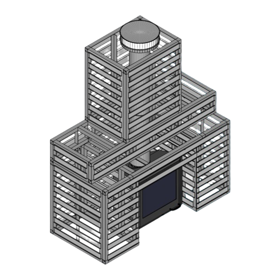
Page 63: Assembled
Front side View Gas Fireplace Natural Gas ASSEMBLED... -
Page 64: Modular Components
1 Standard Chimney UL- FIR- CH 1 Standard Mantle UL- FIR- M 1 Return Panel Set UL- FIR- RTN 1 Base Cabinet UL-BC 2 End Clads UL- ECK U-CARA FASCIA RIGHT CORNER PANEL SET PANELS Standard Panels LEFT CORNER PANEL SET... -
Page 65: 42" Fireplace Modular Components Woodburning
1 Fireplace Module UL- FIR 2 End Clad Oversized UL- ECK-OS 1 Return Panel UL- FIR- RTN-OS 1 Wide Mantle UL- FIR- MW 1 Wide Chimney UL- FIR- CHW U-CARA FASCIA RIGHT CORNER PANEL SET PANELS Standard Panels LEFT CORNER PANEL SET... -
Page 66: 42" Fireplace Modular Components Tv Mount
2 End Clad Oversized UL- ECK-OS 1 Return Panel UL- FIR- RTN-OS 1 Wide Mantle UL- FIR- MW 1 Base Cabinet UL-BC 2 End Clads UL- ECK U-CARA FASCIA RIGHT CORNER PANEL SET PANELS Standard Panels LEFT CORNER PANEL SET... -
Page 67: Standard See-Thru Fireplace Modular (Counter Top)
STACKED MODEL 1 Fireplace Module- UL- FIR 2 Fireplace Module - UL- FIR 4 Standard End Clads- UL- ECK 6 Standard End Clads - UL- ECK U-CARA FASCIA PANELS U-CARA FASCIA PANELS Standard Panels Corner Sets Standard Panels Corner Sets STANDARD PANEL CORNER PANEL SET (RIGHT &... - Page 68 ©2023 HENGESTONE HOLDINGS, INC. THE U-CARA SYSTEM IS PROTECTED UNDER US PAT. 9,453,341 (INTERNATIONAL PATENTS PENDING) U-CARA MODULAR SYSTEMS-PATENT PENDING-GRILLNETICS, FORT COLLINS, CO. 1 800-UNILOCK | UNILOCK.COM...
Need help?
Do you have a question about the U-Cara and is the answer not in the manual?
Questions and answers