
Subscribe to Our Youtube Channel
Related Manuals for Centrometal HPCU360iCMP


Summary of Contents for Centrometal HPCU360iCMP
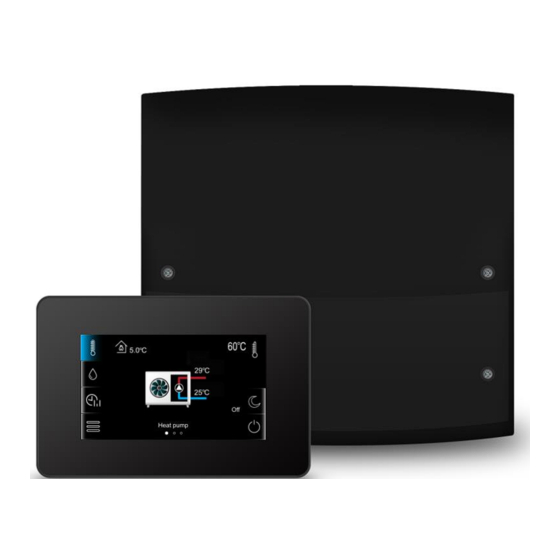
- Page 1 CONTROL UNIT HPCU360iCMP FOR HEAT PUMPS HPx40CM* HPxTouchCM* HPnet300CM* HPx2kCM* * Devices are not included in the standard equipment of the control unit. Technical manual for control unit ISSUE: 1.2_EN 01-2023...
- Page 2 ELECTRIC DEVICE UNDER VOLTAGE! Before any action related to the power supply (cables connection, device installation etc.) check if the control unit is not connected to the power mains! Installation should be done by a person with appropriate electrical qualifications. Improper cables connection could result in the control unit damage.
-
Page 3: Table Of Contents
Table of contents RECOMMENDATIONS REGARDING SAFETY ..4 GENERAL INFORMATION ........5 INFORMATION ABOUT DOCUMENTATION ..5 STORAGE OF DOCUMENTATION ......5 APPLIED SYMBOLS ..........5 DIRECTIVE WEEE 2012/19/UE ......5 USER SETTINGS ..........7 THE CONTROL UNIT DESCRIPTION ...... 8 ......... -
Page 4: Recommendations Regarding Safety
Recommendations regarding safety Use only in heat and cooling system Requirements concerning safety are listed in made in accordance with currently particular sections of this instruction. Apart valid regulations. from them it in necessary to fulfill the Electrical system including the control following requirements. -
Page 5: General Information
General information The HPCU360iCMP control unit is intended for a heat pump control and for controlling of space heating and cooling, and for domestic hot water (DHW) preparation as well. Information about documentation Responsibilities after finishing a period of The control unit manual is divided into two using product: parts: for user and serviceman. -
Page 7: User Settings
USER SETTINGS HPCU360iCMP... -
Page 8: The Control Unit Description
The control unit description The control unit controls the operation of DHW pump loading a DHW tank up to a user- The control unit control defined temperature. Preparation of DHW The control unit is operated using a touch can be programmed in time intervals. The screen. -
Page 9: Heating/Cooling Circuit Settings
DHW tank charging is only active after connecting the DHW tank temperature sensor. Time schedules The control unit includes a function of programming time schedules. situation when user is out of the home or at night, the control unit can decrease the amount of supplied heat energy what affects Tip: color... -
Page 10: User Settings
value. This mode cannot be selected for the - auto mode - automatically switches on DHW tank. heating cooling mode, depending outdoor (weather) - auto-economic mode - the preset temperature. Automatic switch to Auto mode room temperature is maintained at the set is possible only with connected outdoor time periods... -
Page 11: Thermostat
Hour – setting time. Time synchronization Internet module status – function with other connected room information Wi-Fi panels was applied. www.econet24.com web site connection status. Time synchronization will occur Internet module WiFi status – WiFi – at the time difference between information Wi-Fi connection... -
Page 13: Installation And Service Settings
INSTALLATION AND SERVICE SETTINGS HPCU360iCMP... -
Page 14: Hydraulic Schemes
Hydraulic schemes Scheme with hydraulic crossover and DHW tank : 1 – heat pump, 2 – control unit, 3 – Internet module, 4 – the 3-way valve, 5 – DHW tank temp. sensor, 6 – DHW tank, 7 – circulation pump, 8 –... - Page 15 Scheme with buffer and DHW tank : 1 – heat pump, 2 – control unit, 3 – Internet module, 4 – the 3- way valve, 5 – DHW tank temp. sensor, 6 – DHW tank, 7 – circulation pump, 8 – lower buffer temp. sensor, 9 –...
-
Page 16: Technical Data
Technical data exposed to vibrations greater than typical for Control unit normal road transport. Power supply. 230 VAC, 50 Hz Current consumption. 0,4 A 11 The control unit installation Maximum rated current. 6 (6) A Protection class. IP 20 11.1 Installation requirements Ambient temperature. -
Page 17: Installation Of Module
The control unit must not be used as a free-standing device. The control unit should be screwed on to the flat surface, e.g. wall. To screw on the control unit use mounting holes and proper screws. Location and spacing of mounting Using sharp tool cut out holes in four places holes is shown in the figure below. -
Page 18: Temperature Sensors Check
CT-10, CT10-P (NTC10K) Ambient temp. Rated [°C] [Ω] 175200 96358 55046 32554 19872 12488 8059 5330 3605 Mounting temperature sensor: 1 - pipe, 2 – clamps, 3 - thermal insulation, 4 - temperature sensor. 2490 1753 Outdoor temperature sensor. 1256 The control unit cooperates only with outdoor 915.4 677,3... -
Page 19: Output Test
Disconnect electrical supply. The control panel can operate as a Connect the circuit temperature sensor. room panel. Connect electrical cables adjustable circuit pump. Wireless connection. Make electrical connections with Connection of the HPx40CM room thermostat control unit and documentation of the requires connection to the G1 socket of the valve servo. -
Page 20: Connecting The Internet Module
selection of a heating curve will guarantee Cross-section area of wires used room temperature stability – independently to connect room panel should be of the outside temperature. This is why 0.5 mm proper selection of a heating curve is very Max. -
Page 21: Stabilization Of Room Temperature
control unit outside maximum or minimum pins connected to the 230 VAC temperature range for a particular object. mains. For safety reasons, the control 11.13 Stabilization of room temperature unit must be absolutely connected Stability of maintaining room temperature to the 230 VAC power grid, with depends on selection of weather control the sequence of connecting the settings and room thermostat settings. -
Page 22: Connecting The Wires
12.1 Connecting the wires Before connecting the wires, remove the terminal cover from the control unit’s housing. Disconnect power supply before unscrewing the terminal cover of the control unit. Power switch. The control unit terminals cover. Cables should be connected to screw terminals of the (5 and 6) connector. The wires should be secured against pulling out using cable clamps (1). -
Page 23: Electrical Scheme
12.2 Electrical scheme Scheme of electrical connections to the control unit. L N PE - power supply 230 VAC, DHW-S – DHW temperature sensor type CT-10, F1 – main fuse installed inside the control unit, BH – upper buffer temperature sensor type CT- C2-M –... -
Page 24: Service Menu - Structure
13 Service menu – structure Cool water temperature* Entering the menu requires entering Cool water temp. hysteresis* the service password. Buffer operation type Service settings Installation controller Hydraulic crossover Alarm list Hydraulic crossover cooling Min. preset temperature Save/Load setup to/from SD card Save Data Scan to SD card Preset temperature hysteresis Firmware update... - Page 25 Thermostat pump blockade* Valve opening time Contact thermostat Mixer support Inverted thermostat logic AHS enable AHS enable condition Temp. turn on support Temp. turn off support Time to detect no rising temp. Switch to AHS temp. Set temp. during AHS operation Set temp.
-
Page 26: Description Of Service Parameters
14 Description of service parameters Parameters Description Installation control Menu enables turning on particular heating system elements separately and conducting operation correctness tests of selected device. Turning on or off particular selected device is done by pressing the symbol on the screen. ... - Page 27 Cool water temp. hysteresis - if the cool water temperature exceeds the Cool water temperature by the Cool water temp. hysteresis value, the heat pump will stop generating cool water in the buffer. Parameter available only with circuit cooling function on. ...
- Page 28 when Regulation method = Outdoor. Thermostat - activation or deactivation of the room thermostat influence on the heating/cooling circuit operation. Thermostat type - selecting the room thermostat for heating/cooling circuit: room panel or wireless room thermostat. Panel thermostat address - enables setting individual room panel address in case of connecting more room panels to the control unit.
- Page 29 Set temp. during AHS operation - the set temp. of the buffer / low loss header after the AHS is activated. The parameter is visible when selecting AHS enable condition = Outdoor temp. Set temp. during AHS operation hyst. - the hysteresis of the set temperature of the buffer / hydraulic clutch (hysteresis of re-activating the AHS heating).
-
Page 30: Replacing Components
15 Replacing components firmware update the control unit’s power supply must be disconnected. 15.1 Mains fuse replacement Before starting firmware update all The fuse is located under the control unit peripheral devices operating with cover, next to the terminals at high-voltage the central must be disconnected side. - Page 32 Centrometal d.o.o. Glavna 12 40306 MACINEC, CROATIA komercijala@centrometal.hr www.centrometal.hr...
Need help?
Do you have a question about the HPCU360iCMP and is the answer not in the manual?
Questions and answers