Table of Contents
Advertisement
Quick Links
TCA/TCAS SYSTEM MANUAL
Manual Number:
Issue Date:
BTU International
(Corporate
Headquarters)
BTU Europe Limited
BTU Overseas, Limited 01-116, LHK Building
24-Hour Help
TM 5250517 Rev. 0
Apr 15/2003
23 Esquire Road
N. Billerica, MA 01862 USA
Phone: 1.978.667.4111
Phone: 1.800.800.8998 (Outside MA)
Fax: 1.978.670.2796
Unit 14 Armstrong Mall, Southwood Summit Centre
Farnborough, Hants, England GU14 ONR
Phone: 44.1252.66.0010
Fax: 44.1252.66.0011
701 Sims Drive
Singapore 387383
Phone: 65.741.4567
Fax: 65.841.4567
USA: 1.800.998.0666
UK: 0.800.96.8910
Ireland: 1.800.55.7687
Mexico: 1.800.547.1783
TCA11014
Advertisement
Chapters
Table of Contents

Summary of Contents for BTU TCA
- Page 1 Fax: 1.978.670.2796 BTU Europe Limited Unit 14 Armstrong Mall, Southwood Summit Centre Farnborough, Hants, England GU14 ONR Phone: 44.1252.66.0010 Fax: 44.1252.66.0011 BTU Overseas, Limited 01-116, LHK Building 701 Sims Drive Singapore 387383 Phone: 65.741.4567 Fax: 65.841.4567 24-Hour Help USA: 1.800.998.0666 UK: 0.800.96.8910...
-
Page 2: Limitation Of Liability
LIMITATION OF LIABILITY BTU International, Inc. (BTU) believes that the information in this publication is correct as of the print date. BTU reserves the right to make changes in specifications and information without notice. BTU is not responsible for inadvertent errors. -
Page 3: Table Of Contents
TCA/TCAS SYSTEM MANUAL CONTENTS LIMITATION OF LIABILITY ........... . 1-2 LIST OF REVISIONS . -
Page 4: Contents
TCA/TCAS SYSTEM MANUAL Cooling System Requirements..........2-7 Equipment Data. - Page 5 TCA/TCAS SYSTEM MANUAL Lubricate the Drive Chain and the Drive Chain Sprockets..... . . 5-23 Lubricate the Idler Pulley Bearings........5-25 Fill the Drive Motor Oil.
- Page 6 TCA/TCAS SYSTEM MANUAL Electrical and Control System..........7-21 Replace the UPS..
-
Page 7: Introduction
Technical Help. I.3.1 If you have problems when you install or operate the equipment, review the installation procedures. If the problem continues, call BTU. Use the telephone numbers that are printed on the front cover of this manual. I.3.2 Keep the reference manuals and serial number available when you call. -
Page 8: Equipment Label
TCA/TCAS SYSTEM MANUAL Equipment Label. I.4.1 The serial number of the equipment is on the front cover of the manual and on the equipment label (located near the electrical connections). Make sure that you know the serial number when you call for information. -
Page 9: Tools And Equipment
TCA/TCAS SYSTEM MANUAL Tools and Equipment. I.5.1 The following tools are necessary to maintain the equipment: • Ammeter (clip-on) • Cutters • Drift pin punch set • Feeler gauges • Grease gun • Hammer • Hex wrenches • Lamp puller (or a plastic sleeve) •... -
Page 10: Manual Description
Section Description INTRODUCTION Gives instructions to use this manual and references to technical resources that are available from BTU. SAFETY Gives safety related practices that are used in this manual and dangers that are related to the use of the equipment. -
Page 11: Symbols, Abbreviations, And Terms
TCA/TCAS SYSTEM MANUAL Symbols, Abbreviations, and Terms. NOTE The following table is applicable to all BTU products. I.8.1 For a list of symbols, abbreviations, and terms that are used in this manual, refer to Table Table I-3. Symbols, Abbreviations, and Terms... - Page 12 TCA/TCAS SYSTEM MANUAL Symbol/ Abbreviation/Term Definition Control Circuit The circuit of a control apparatus or system that carries the electrical signals directing the performance of the controller Controller A device or group of devices that serves to govern, in some predetermined...
- Page 13 TCA/TCAS SYSTEM MANUAL Symbol/ Abbreviation/Term Definition Forming Gas Any mixture formed by combining two or more gases. Where a furnace uses H as its primary process gas, the term forming gas usually refers to the mixture formed when a large amount of inert N...
- Page 14 Manometer An instrument for measuring static gas pressures, usually in inches of water column (also magnehelic) Material Return An authorization number assigned by BTU that is used when you return parts Authorization Number for warranty replacement (also MRA number) Megabyte...
- Page 15 TCA/TCAS SYSTEM MANUAL Symbol/ Abbreviation/Term Definition Newton meter Nitrogen NFPA National Fire Protection Agency Non-Explosive Gas A gas or gas mixture that is inert and non-combustible such as N Nominal Pipe Thread Ø Phase Oxygen Outside Diameter Original Equipment Manufacturer...
- Page 16 A mode of operation when the furnace has stabilized and is ready to process products RECP Receptacle Resistor Return Authorization An authorization number assigned by BTU that is used when returning parts for Number paid repair (also RA number) Right Hand Root mean square scfm...
- Page 17 Ultrasonic Belt Cleaner Volt Volts Alternating Current Volts Direct Current Watt WINCON (Windows® software) WINCON Controller Proprietary software that controls the operation of BTU thermal processing Software equipment that uses Microsoft Windows® Intro TM 5250517 Rev. 0 Page I-11 Apr 15/2003...
- Page 18 TCA/TCAS SYSTEM MANUAL Intro TM 5250517 Rev. 0 Page I-12 Apr 15/2003...
-
Page 19: Safety
TCA/TCAS SYSTEM MANUAL SAFETY WARNING ARNING The customer must be aware of the outgasses and emissions of their process. Outgases and emissions can cause injury. Also, the customer should investigate the need for an air permit for organic flux emissions. -
Page 20: Safety Precautions
TCA/TCAS SYSTEM MANUAL Safety Precautions. S.4.1 The equipment has high electrical voltages, high temperatures, high gas pressures, and moving parts. If you obey the instructions in this and other manuals when you install, operate, and do maintenance of the equipment, you will reduce or prevent exposure to these dangers. - Page 21 TCA/TCAS SYSTEM MANUAL Precaution Description DANGER ANGER High voltage is used to operate the equipment. Death or serious injury can occur if you touch high voltage connections. • In the U.S., give instruction in electrical handling procedures as specified in the...
- Page 22 TCA/TCAS SYSTEM MANUAL Precaution Description • Plumbing lines have labels with the contents and direction of flow (labels have a Plumbing green background with white lettering). When you do maintenance, obey the labels. Use the lockout/tagout procedure on gas lines when you do maintenance on the gas system.
-
Page 23: Safety Identification
TCA/TCAS SYSTEM MANUAL Safety Identification. S.5.1 DANGERs, WARNINGs, CAUTIONs, and NOTEs. S.5.1.1 DANGERs, WARNINGs, CAUTIONs, and NOTEs give safety and work-related information. DANGER ANGER Shows that an event or an unsafe practice may occur that will cause death to personnel. -
Page 24: Electrical Hazards
TCA/TCAS SYSTEM MANUAL S.5.2 Electrical Hazards. S.5.2.1 The type of electrical hazard is identified at the beginning of maintenance procedures that include electrical work. Refer to Table S-2. Table S-2. Electrical Hazards Label Voltage Conditions Required Safety Equipment • Safety glasses... -
Page 25: Safety Labels
TCA/TCAS SYSTEM MANUAL NOTE Not all the safety labels in the illustrations are on your furnace. S.5.3 Safety Labels. S.5.3.1 Safety labels are used on the equipment and in the manuals to warn of hazards. For examples, refer to Figure S-1. - Page 26 TCA/TCAS SYSTEM MANUAL Item Colors Description Yellow, Black Temperature Hazard Yellow, Black Electrical Hazard Yellow, Black Temperature Hazard Yellow, Black Potassium Hydroxide Hazard Orange, Black Pressurized Line Hazard Red, White Disconnect Power Warning Yellow, Black Line Voltage Orange, Black Voltage Selector Switch Warning...
- Page 27 TCA/TCAS SYSTEM MANUAL MISC1023R1 Figure S-1. Safety Labels Safety TM 5250517 Rev. 0 Page S-9 Apr 15/2003...
- Page 28 TCA/TCAS SYSTEM MANUAL MISC1052 Figure S-1 (Sheet 1). Safety Labels Safety TM 5250517 Rev. 0 Page S-10 Apr 15/2003...
- Page 29 TCA/TCAS SYSTEM MANUAL MISC1024R1 Figure S-1 (Sheet 2). Safety Labels Safety TM 5250517 Rev. 0 Page S-11 Apr 15/2003...
- Page 30 TCA/TCAS SYSTEM MANUAL MISC1053 Figure S-1 (Sheet 3). Safety Labels Safety TM 5250517 Rev. 0 Page S-12 Apr 15/2003...
- Page 31 TCA/TCAS SYSTEM MANUAL MISC1054 Figure S-1 (Sheet 4). Safety Labels Safety TM 5250517 Rev. 0 Page S-13 Apr 15/2003...
- Page 32 TCA/TCAS SYSTEM MANUAL MISC1050R1 Figure S-1 (Sheet 5). Safety Labels Safety TM 5250517 Rev. 0 Page S-14 Apr 15/2003...
-
Page 33: Standard And Optional Safety Equipment
TCA/TCAS SYSTEM MANUAL Standard and Optional Safety Equipment. S.6.1 Standard Equipment. S.6.1.1 Refer to Table S-4. Table S-4. Safety Features Device Description Let the operator stop equipment operation in an emergency. Interlocks Interlocks de-energize power, keep operation safe, and prevent part damage. - Page 34 TCA/TCAS SYSTEM MANUAL TCA11033 Figure S-2. Safety Switches and Interlocks (Air / N , Typical) Figure Legend Item Description NOTE This is a typical example. Your furnace may be different. Main Disconnect Switch (Option) Safety TM 5250517 Rev. 0 Page S-16...
- Page 35 TCA/TCAS SYSTEM MANUAL TCA11034 Figure S-2 (Sheet 1). Safety Switches and Interlocks (H , Typical) Figure Legend Item Description NOTE This is a typical example. Your furnace may be different. Main Disconnect Switch (Option) Safety TM 5250517 Rev. 0 Page S-17...
-
Page 36: Safety Procedures
TCA/TCAS SYSTEM MANUAL Safety Procedures. S.7.1 Lockout/Tagout Procedure (Without Main Disconnect Switch Option). DANGER ANGER This equipment uses high voltage electricity. If you do not do the lockout/tagout procedure when advised, death can result. DANGER ANGER All liquid and gas supplies must be shut and electrical power de-energized before you do maintenance that requires a lockout/tagout. -
Page 37: Lockout/Tagout Procedure (With Main Disconnect Switch Option
TCA/TCAS SYSTEM MANUAL S.7.2 Lockout/Tagout Procedure (With Main Disconnect Switch Option). NOTE You can use equivalent tools and equipment. S.7.2.1 Special Tools and Equipment. • Padlock DANGER ANGER This equipment uses high voltage electricity. If you do not use the lockout/tagout procedure when advised, death can result. - Page 38 TCA/TCAS SYSTEM MANUAL S.7.2.3 Procedure (Remove Lockout/Tagout). S.7.2.3.1 Remove lockout tag from main disconnect switch. S.7.2.3.2 Remove the padlock. S.7.2.3.3 Turn the handle CW to ON. S.7.2.3.4 Remove the lockout tag from liquid and gas supplies. S.7.2.3.5 Do a normal startup of the equipment. Refer to page 3-7, paragraph 3.5,...
- Page 39 TCA/TCAS SYSTEM MANUAL BELT1004 Figure S-3. Lockout/Tagout Procedure (Typical) Safety TM 5250517 Rev. 0 Page S-21 Apr 15/2003...
-
Page 40: Emergency Stop Procedure
TCA/TCAS SYSTEM MANUAL S.7.3 Emergency Stop Procedure. NOTE You can use equivalent tools and equipment. S.7.3.1 Tools and Equipment. • None NOTE EMOs de-energize power to the heater, the belt drive, and the PC. S.7.3.2 Procedure. S.7.3.2.1 Press a red EMO. -
Page 41: Disposal Of Equipment
Environmentally Responsible Recycling of Equipment. S.8.1.1 BTU believes in Environmentally Responsible Recycling of Equipment at the end of life of this equipment. If the equipment is no longer needed, consider the following: • Can you extend the life of the equipment? •... -
Page 42: Disposal Of Hazardous Maintenance Materials
TCA/TCAS SYSTEM MANUAL Disposal of Hazardous Maintenance Materials. S.9.1 For information about hazardous materials related to maintenance and operation of your equipment, refer to Appendix C, MATERIAL SAFETY DATA SHEETS or standard practice of your facility. S.9.2 Dispose of hazardous materials in accordance with local, state, and federal regulations. -
Page 43: System Description
TCA/TCAS SYSTEM MANUAL SYSTEM DESCRIPTION Contents. Equipment Description........... . . 1-2 Equipment Features and Options. -
Page 44: Equipment Description
TCA/TCAS SYSTEM MANUAL Equipment Description. 1.2.1 Furnaces deliver a specific heat profile for a specific conveyor speed. Conveyor speed, zone temperatures, mixture of cover gas, gas flow rates, and exhaust rates interact during product processing. The FCU and the operating software automate the operation. A PC with WINCON software interface between the operator and the FCU. - Page 45 TCA/TCAS SYSTEM MANUAL Chapter 1 TM 5250517 Rev. 0 Page 1-3 Apr 15/2003...
- Page 46 TCA/TCAS SYSTEM MANUAL Chapter 1 TM 5250517 Rev. 0 Page 1-4 Apr 15/2003...
- Page 47 TCA/TCAS SYSTEM MANUAL Chapter 1 TM 5250517 Rev. 0 Page 1-5 Apr 15/2003...
- Page 48 TCA/TCAS SYSTEM MANUAL Chapter 1 TM 5250517 Rev. 0 Page 1-6 Apr 15/2003...
- Page 49 TCA/TCAS SYSTEM MANUAL Chapter 1 TM 5250517 Rev. 0 Page 1-7 Apr 15/2003...
- Page 50 TCA/TCAS SYSTEM MANUAL Chapter 1 TM 5250517 Rev. 0 Page 1-8 Apr 15/2003...
- Page 51 TCA/TCAS SYSTEM MANUAL Chapter 1 TM 5250517 Rev. 0 Page 1-9 Apr 15/2003...
- Page 52 TCA/TCAS SYSTEM MANUAL Chapter 1 TM 5250517 Rev. 0 Page 1-10 Apr 15/2003...
-
Page 53: Equipment Locator
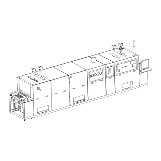
TCA/TCAS SYSTEM MANUAL Equipment Locator. 1.4.1 Refer to Figure 1-1. TCA11032R1 Figure 1-1. TCA Major Components (Typical) Figure Legend Item Description Entrance Table Profile TC Ports EMO Button Main Disconnect Switch (Option) Exhaust Stack (Hydrogen Furnaces Only) Electrical Connections Gas Flowmeter Panel... -
Page 54: Frame And Panel System
TCA/TCAS SYSTEM MANUAL Frame and Panel System. 1.5.1 No Additional Information. Conveyor System. 1.6.1 General. 1.6.1.1 The drive and catenary lets the belt stretch before you remove a section of belt and increases belt life. 1.6.1.2 Belt tracking has a bolt threading mechanism to adjust the shaft/pulleys. - Page 55 TCA/TCAS SYSTEM MANUAL DIM.A BELT1003R1 Figure 1-2. External Belt Drive Pulley Adjustment Bolts Chapter 1 TM 5250517 Rev. 0 Page 1-13 Apr 15/2003...
- Page 56 TCA/TCAS SYSTEM MANUAL Figure Legend Item Description Splice Wire Tension Rollers Belt Shear Pin Drive Sprocket Drive Belt Drive Motor Catenary Ultrasonic Belt Cleaner Drive Pulley Belt Tracking Locknuts Drive Pulley Shaft Pressure Pulley Pressure Pulley Shaft Pressure Pulley Tension Sprint Tension Spring Adjustment Locknuts Dim.
-
Page 57: Electrical And Control System
TCA/TCAS SYSTEM MANUAL Electrical and Control System. 1.7.1 Controls. 1.7.1.1 Zones are controlled by: • Microprocessor channel • SSRs • Programmable trims • Type K TCs (standard) 1.7.1.2 The gas panel is on the RH side viewed from the entrance. -
Page 58: Light Tower, Three- Or Four-Color (Option)
TCA/TCAS SYSTEM MANUAL 1.7.5 Light Tower, Three- or Four-Color (Option). 1.7.5.1 Refer to Table 1-2 for the color coding of a standard light tower. 1.7.5.2 If the light tower is customized, refer to Appendix A, DRAWINGS, SPECIFICATIONS, OPTIONS. Table 1-2. Standard Light Tower Indicators... -
Page 59: Main Control Panel (Mc-98)
TCA/TCAS SYSTEM MANUAL 1.7.6 Main Control Panel (MC-98). 1.7.6.1 Refer to Figure 1-3. INSTRUMENT MASTER DRIVE POWER START MASTER HEAT STOP MISC1032 Figure 1-3. Main Control Panel (MC-98) Figure Legend Item Description INSTRUMENT POWER Selector switch. Turns instrument power on and off. The selector lights up when it is activated. - Page 60 TCA/TCAS SYSTEM MANUAL 1.7.6.2 System Software. 1.7.6.2.1 Software includes pre-loaded menu-driven software that performs all system setup, calibration. programming, scheduling, operating, and monitoring functions. Refer to Table 1-3. 1.7.6.2.2 Software functions can be done from the Main Temperature Screen, which is displayed when you first power up the system.
-
Page 61: Atmosphere System
TCA/TCAS SYSTEM MANUAL Atmosphere System. 1.8.1 Atmosphere Control Panel (Hydrogen Furnaces Only). 1.8.1.1 Refer to Figure 1-4. GAS SYSTEM COVER GAS COVER GAS PURGE RESET TIMED PURGE COVER GAS READY 30 MINUTES TCA11003 Figure 1-4. Atmosphere Control Panel (Hydrogen Furnaces Only) - Page 62 TCA/TCAS SYSTEM MANUAL 1.8.1.2 Atmosphere Control. 1.8.1.2.1 The equipment is designed to operate in a clean air atmosphere. Various features are used to give the correct environment for to process your product. These features are used in conjunction with each other to allow you to control the atmosphere within your equipment.
- Page 63 TCA/TCAS SYSTEM MANUAL HEATED VENTURI SECTION EXHAUST BELT1008R1 Figure 1-6. Temperature and Gas Controls Figure Legend Item Description Monitor Keyboard Mounting Assembly Flowmeter Chapter 1 TM 5250517 Rev. 0 Page 1-21 Apr 15/2003...
-
Page 64: Heating System
TCA/TCAS SYSTEM MANUAL Heating System. 1.9.0.1 Temperature Control. 1.9.0.1.1 The equipment has separately controlled heated tones. 1.9.0.1.2 The system controller usually consists of the FCU and a PC. Simpler equipment may use a controller, described later. The system controller maintains accurate temperatures at the setpoint values through PID temperature control loops. - Page 65 TCA/TCAS SYSTEM MANUAL Figure Legend Item Description Relay Control Signal TC Input Heater AC Input Chapter 1 TM 5250517 Rev. 0 Page 1-23 Apr 15/2003...
-
Page 66: Cooling System
TCA/TCAS SYSTEM MANUAL 1.10 Cooling System. 1.10.1 No Additional Information. 1.11 Muffle System. 1.11.1 No Additional Information. Chapter 1 TM 5250517 Rev. 0 Page 1-24 Apr 15/2003... -
Page 67: Installation
TCA/TCAS SYSTEM MANUAL INSTALLATION WARNING ARNING You risk serious injury and cancelled manufacturer’s warranty if you do not obey the instructions in this manual. Contents. Facility Requirements............2-2 Plumbing Requirements.. -
Page 68: Facility Requirements
TCA/TCAS SYSTEM MANUAL Facility Requirements. 2.2.1 Refer to your facility drawings and Appendix A, DRAWINGS, SPECIFICATIONS, OPTIONS to plan furnace position. Note the following: • There must be sufficient overhead clearance and swing room. • There must be sufficient airflow around the equipment. -
Page 69: Water Requirements
TCA/TCAS SYSTEM MANUAL Water Requirements. CAUTION AUTION Make sure that there is cooling water (if applicable) before you operate the equipment. This prevents damage to gaskets and heat exchangers. CAUTION AUTION Instal a pressure relief valve (if you use a recirculating water supply). This prevents damage to pipes. - Page 70 TCA/TCAS SYSTEM MANUAL DIM.A DIA. B BELT1000R1 Figure 2-1. Exhaust Setup (Typical) Figure Legend Item Description Dim. A 46 cm (18 in.) Dia. B 46 cm (18 in.) Exhaust Duct Adjustable Damper Exhaust Hood Exhaust Stack Cabinet Vent (option, usually with explosive equipment) Chapter 2 TM 5250517 Rev.
-
Page 71: Cda And N2 Requirements
TCA/TCAS SYSTEM MANUAL CDA and N Requirements. CAUTION AUTION Purge gas pipes before you connect them to the system. This prevents system contamination. CAUTION AUTION Connect all gas pipes to the correct facility hookup to prevent system contamination. CAUTION AUTION Use clean, dry, oil-free gases. - Page 72 TCA/TCAS SYSTEM MANUAL MISC1026 Figure 2-2. CDA Requirements Figure Legend Item Description Air Purifying System Air Compressor Aftercooler Separator Pre-filter Fine Filter Bypass Valves Post-filter To furnace air inlet Air Dryer Drains Chapter 2 TM 5250517 Rev. 0 Page 2-6...
-
Page 73: Air Requirements
TCA/TCAS SYSTEM MANUAL Air Requirements. 2.7.1 Make sure that there is enough fresh air to compensate for the exhaust system requirements. Use the information in this chapter and also on your Installation Drawing (Appendix A, DRAWINGS, SPECIFICATIONS, OPTIONS) to calculate the amount of fresh air required. -
Page 74: Equipment Data
TCA/TCAS SYSTEM MANUAL 2.12 Equipment Data. 2.12.1 Refer to Table 2-1. Table 2-1. Equipment Data Item Data NOTE Add the dimensions of the shipping skids/crates to the furnace dimension. Shipping Skids Length +10 cm (4 in.) Width +10 cm (4 in.) Height +15 cm (6 in.) - Page 75 TCA/TCAS SYSTEM MANUAL Item Data Water temperature increase Refer to Appendix A, DRAWINGS, SPECIFICATIONS, OPTIONS or the specifications Water pressure at furnace Refer to Appendix A, DRAWINGS, SPECIFICATIONS, OPTIONS or the specifications Nominal flow per heat exchanger Refer to Appendix A, DRAWINGS,...
-
Page 76: Procedures
TCA/TCAS SYSTEM MANUAL Item Data Compressed Dry Air Requirements Dewpoint Refer to Appendix A, DRAWINGS, SPECIFICATIONS, OPTIONS or the specifications Filter capability Refer to Appendix A, DRAWINGS, SPECIFICATIONS, OPTIONS or the specifications Filter pipe size Refer to Appendix A, DRAWINGS,... - Page 77 Sign the delivery receipt making sure that you record the visible damage and notify the carrier immediately. File a damage claim with the transportation carrier. Call BTU. If you need more information for insurance purposes, call BTU. Chapter 2 TM 5250517 Rev. 0 Page 2-11...
-
Page 78: Move
• Crane support • 5 x 21 cm (2 x 8 in.) wood supports (5 cm (2 in.) wider than furnace) (2) CAUTION AUTION BTU is not responsible for damage that occurs if you move or unpack the furnace. CAUTION AUTION Do not attach components to one another until you put the equipment in the final position. - Page 79 TCA/TCAS SYSTEM MANUAL 2.13.2.3 Procedure (with Forklift Truck). 2.13.2.3.1 Put the tines through the end of the skid until they reach the component lifting areas. 2.13.2.3.2 Lift the end until there is clearance to put an industrial dolly under the skid at the lifting point.
- Page 80 TCA/TCAS SYSTEM MANUAL BELT1001R1 Figure 2-3. Equipment Lifting Points Figure Legend Item Description Top Panels Side Panels Frame Lifting Points Lifting Straps Shipping Skid Chapter 2 TM 5250517 Rev. 0 Page 2-14 Apr 15/2003...
-
Page 81: Store
TCA/TCAS SYSTEM MANUAL 2.13.3 Store. NOTE You can use equivalent tools and equipment. 2.13.3.1 Special Tools and Equipment. • Desiccant 2.13.3.2 Procedure. 2.13.3.2.1 Store the furnace in the original shipping containers. 2.13.3.2.2 Put the furnace in an area with a nominal ambient temperature of 21°C (70°F). -
Page 82: Installation
TCA/TCAS SYSTEM MANUAL NOTE Do the steps in the order of this procedure. 2.14 Installation. 2.14.1 Install the Belt. 2.14.1.1 Refer to page 7-6, paragraph 7.4.2, Replace the Conveyor Belt (Belt Installed Now). 2.14.2 Adjust the Furnace Level. 2.14.2.1 Refer to page 5-8, paragraph 5.3.2, Adjust the Furnace Level. -
Page 83: Set Up The Product Feed Conveyor
TCA/TCAS SYSTEM MANUAL 2.14.5 Set Up the Product Feed Conveyor. 2.14.5.1 Parts. Catalog Number Nomenclature None NOTE You can use equivalent tools and equipment. 2.14.5.2 Special Tools and Equipment. • None NOTE If you have a product feed conveyor to connect to the entrance end of the equipment, use the following procedure as a guide to ensure correct product transfer and to prevent misleading of the product. -
Page 84: Assemble The Equipment (If Shipped In Separate Sections)
TCA/TCAS SYSTEM MANUAL 2.14.6 Assemble the Equipment (If Shipped in Separate Sections). 2.14.6.1 Parts. Catalog Number Nomenclature None 2.14.6.2 Special Tools and Equipment. • Floor jack • Torque wrench, 80 in.-lb NOTE If your equipment was shipped in separate sections, you must assemble the sections. - Page 85 TCA/TCAS SYSTEM MANUAL TCA11001 Figure 2-4. Aligning the Sections Figure Legend Item Description Atmosphere Curtains Gas Plenums Entrance Section Heating Section Cooling Section Exit Section Chapter 2 TM 5250517 Rev. 0 Page 2-19 Apr 15/2003...
- Page 86 TCA/TCAS SYSTEM MANUAL BELT1009 Figure 2-5. Joining Sections with Clamps Figure Legend Item Description Entrance Table Heating Section Cooling Section Exit Table Process Chamber Heating Section Cooling Section Chapter 2 TM 5250517 Rev. 0 Page 2-20 Apr 15/2003...
-
Page 87: Connect Electrical Supply
TCA/TCAS SYSTEM MANUAL CAUTION AUTION The equipment is designed to operate with the voltage, amperage, cycle, phase, and wire specifications at your site. You must make sure that the electrical supply is installed correctly and that it conforms to local, state, and national wiring codes. -
Page 88: Installation Checklist
TCA/TCAS SYSTEM MANUAL 2.14.7.3.3 At the equipment electrical cabinet, do as follows: Install the correct hub to the equipment electrical cabinet. Connect the wires from the facility electrical cabinet to the connections in the disconnect or main contactor. 2.14.7.3.4 Examine the torque of the electrical connections (distribution terminal blocks and grounds, CB and SSR connections, incoming power connections, main disconnect and large terminal blocks, transformer connections and jumpers). -
Page 89: Operation
TCA/TCAS SYSTEM MANUAL OPERATION WARNING ARNING Obey all safety precautions when you operate and maintain the equipment. Otherwise, personal injury and equipment can result. WARNING ARNING Only qualified personnel should operate and maintain the equipment. WARNING ARNING Make sure that there are no personnel or loose tools in the equipment and that all doors are shut before you start equipment operation. -
Page 90: General
TCA/TCAS SYSTEM MANUAL General. DANGER ANGER Before you start the furnace, make sure that all gas lines are connected correctly. If you have a hydrogen system, a defective gas connection can cause an unstable condition. 3.2.1 This chapter gives instructions to operate the furnace. Read this manual and the WINCON Operation Manual before you operate the equipment. -
Page 91: Summarized Checklist
TCA/TCAS SYSTEM MANUAL Summarized Checklist. 3.3.1 For a summary of the steps necessary to operate the furnace, refer to Table 3-1. Table 3-1. Summarized Checklist Step Item * * * All Furnaces * * * Calculate the required cover gas... -
Page 92: Calculate Cover Gas Flow (All Furnaces)
TCA/TCAS SYSTEM MANUAL WARNING ARNING If H is used as the cover gas, a high O level can cause an unstable condition. Do not remove an atmosphere curtain assembly. Do not remove an atmosphere curtain assembly when the equipment operates. Make sure that three curtains minimum are down at al times in the entrance and exit of the furnace. - Page 93 TCA/TCAS SYSTEM MANUAL 3.4.2 Calculate the per-minute volume of cover gas as follows: 3.4.2.1 Measure the muffle width, length, and height (including heating and cooling sections but no the area beneath the atmosphere curtains). 3.4.2.2 Calculate the volume of the process chamber as follows: Volume = Width x Length x Height 3.4.2.3...
-
Page 94: Calculate Atmosphere Curtain Flow Rates
TCA/TCAS SYSTEM MANUAL 3.4.5 Calculate Atmosphere Curtain Flow Rates. 3.4.5.1 Calculate the amount of gas that must flow from the plenums: 3.4.5.1.1 Measure the width, length, and height of the area under the atmosphere curtains at the entrance of the muffle. -
Page 95: Start And Operate
TCA/TCAS SYSTEM MANUAL * * * * * * * * * * ALL FURNACES * * * * * * * * * * Start and Operate. WARNING ARNING Make sure that all gas input lines are connected to the correct inlets. - Page 96 TCA/TCAS SYSTEM MANUAL NOTE The water temperature must stay within the limits. The nominal water operating temperature for your furnace is 20°C (68°F). If you are operating the furnace with a water cooler, the minimum operating temperature can be as low as 5°C (40°F). If the water is filtered, close the water filter bypass line.
- Page 97 TCA/TCAS SYSTEM MANUAL CAUTION AUTION ° ° The heat-up rate must not be more than 2 C per minute or 50 C per hour for muffle-type furnaces. The controller is software-limited and must not be changed. Otherwise, the muffle may heat unevenly and cause damage.
- Page 98 TCA/TCAS SYSTEM MANUAL 3.5.15 Change flowrate as follows: 3.5.15.1 Examine the flowmeters for the correct flow rates to the entrance and exit curtains. NOTE The stack slot indicates the position of the damper plate. When the slot is vertical, the valve is open. When the nut is tight, the stack nut forms a gas tight seal.
- Page 99 TCA/TCAS SYSTEM MANUAL * * * * * * * * * * ALL FURNACES * * * * * * * * * * 3.5.17 When the SMG displays READY, load product on the conveyor. CAUTION AUTION Product that exits the furnace is hot. Use protective gloves to handle product.
-
Page 100: Normal Shutdown
TCA/TCAS SYSTEM MANUAL Normal Shutdown. CAUTION AUTION Shut down the furnace with a cooldown or shutdown recipe. 3.6.1 Remove all product from the furnace. 3.6.2 If applicable, shut explosive gas at the source. 3.6.3 Run your cooldown recipe until the furnace is cool (less than 100°C). -
Page 101: System Alerts Or Alarms
TCA/TCAS SYSTEM MANUAL System Alerts or Alarms. NOTE System alarms can occur for various reasons. When there is a system alarm, the system typically sounds an alarm that indicates that operator action is required. With the optional light tower, the red light comes on. -
Page 102: Respond To Interlock And Alarm Conditions
TCA/TCAS SYSTEM MANUAL 3.9.6 Respond to Interlock and Alarm Conditions. 3.9.6.1 For interlock alarm conditions and recovery procedures, refer to Table 3-5. 3.9.6.2 Recovery procedures assume that you first acknowledge an alarm. Table 3-5. Interlock and Alarm Conditions and Recovery... - Page 103 TCA/TCAS SYSTEM MANUAL Condition Subsystem Status Result Action NOTE Burnoff stacks are only used with hydrogen furnaces. Burnoff Failure Heaters On Open circuit in an exhaust Repair ignitor circuit (failure of one Conveyor On ignitor causes burnoff Reset controller alarm in...
-
Page 104: Operate Options
TCA/TCAS SYSTEM MANUAL 3.10 Operate Options. 3.10.1 Operate the Belt Cleaners. 3.10.1.1 Controls for the rotary brush cleaner and ultrasonic belt cleaner options are integrated into the software package. If your have any of these options, the specific option is configured into your software at the time of manufacture. -
Page 105: Operate The Heat Barrier
TCA/TCAS SYSTEM MANUAL 3.10.7 Operate the Heat Barrier. 3.10.7.1 The heat barrier gate must be near the product to keep zone openings that are programmed for different temperatures or atmospheres to a minimum. Barrier gates have a locking collar on the inlet tube that sets the height of the gate. - Page 106 TCA/TCAS SYSTEM MANUAL Chapter 3 TM 5250517 Rev. 0 Page 3-18 Apr 15/2003...
-
Page 107: Troubleshooting
TCA/TCAS SYSTEM MANUAL TROUBLESHOOTING WARNING ARNING Obey all safety precautions when you operate and maintain the equipment. Otherwise, personal injury and equipment can result. WARNING ARNING Properly dispose of all hazardous waste. WARNING ARNING Only qualified personnel should operate and maintain the equipment. -
Page 108: Troubleshoot The Conveyor System
TCA/TCAS SYSTEM MANUAL Troubleshoot the Conveyor System. 4.3.1 Troubleshoot the Conveyor System. 4.3.1.1 Refer to Table 4-1 Table 4-1. Troubleshoot the Conveyor System Problem Possible Cause Possible Solution Conveyor system runs at erratic Blocked process chamber or edges Correct the problem. - Page 109 TCA/TCAS SYSTEM MANUAL Problem Possible Cause Possible Solution Examine optical shaft encoder Replace drive motor, if necessary. output with a multimeter (0 to 5 V dc square wave) for a defective drive motor shaft encoder If product feed conveyor is used, Clear downstream equipment.
-
Page 110: Troubleshoot The Atmosphere System
TCA/TCAS SYSTEM MANUAL Troubleshoot the Atmosphere System. 4.4.1 Troubleshoot the Temperature System. 4.4.1.1 Refer to Table 4-1 Table 4-2. Troubleshoot the Temperature System Problem Possible Cause Possible Solution Product processing quality is A temperature profile problem that Make sure that all zones and... - Page 111 TCA/TCAS SYSTEM MANUAL Problem Possible Cause Possible Solution Incorrect furnace controller Examine the furnace controller configuration configuration for the correct installations. Incorrect belt speed Refer to page 4-2, paragraph 4.3.1, Troubleshoot the Conveyor System. Products exiting the furnace are Cooler not working Examine cooling water flow.
- Page 112 TCA/TCAS SYSTEM MANUAL Problem Possible Cause Possible Solution Defective SSR Examine the SSR with an ohmmeter. Replace if necessary. Tripped power CB Examine the CB, fuses, interlocks and EMOs. Pressure switch senses low gas Examine for low air pressure. pressure Replace gas pressure switch, if necessary.
-
Page 113: Troubleshoot The Atmosphere System
TCA/TCAS SYSTEM MANUAL 4.4.2 Troubleshoot the Atmosphere System. 4.4.2.1 Refer to Table 4-3 Table 4-3. Troubleshoot the Atmosphere System Problem Possible Cause Possible Solution Low gas flow volume Low gas inlet pressure Examine gas inlet pressure regulator setting or air/gas supply pressure to the furnace. - Page 114 TCA/TCAS SYSTEM MANUAL Problem Possible Cause Possible Solution Large decrease in gas sample flow Contaminated filter Replace the filter. rate to O analyzer Incorrect flow settings Adjust the N source to 3.5 scfh (1.5 lpm) (same as the sample). Blocked gas sample lines or...
-
Page 115: Troubleshoot The O2 Analyzer (Option)
TCA/TCAS SYSTEM MANUAL 4.4.3 Troubleshoot the O Analyzer (Option). 4.4.3.1 Refer to Table 4-4 Table 4-4. Troubleshoot the O Analyzer Problem Possible Cause Possible Solution Incorrect O readings analyzer input contaminated or Let the O analyzer purge with an exposed to the atmosphere... -
Page 116: Troubleshoot The Electrical And Control System
TCA/TCAS SYSTEM MANUAL Troubleshoot the Electrical and Control System. 4.5.1 Troubleshoot the Product Tracking/Smart Tracker. 4.5.1.1 Refer to Table 4-6 Table 4-6. Troubleshoot the Product Tracking Problem Possible Cause Possible Solution Monitor shows multiple counts Product sensor triggers a count... -
Page 117: Preventive Maintenance
TCA/TCAS SYSTEM MANUAL PREVENTIVE MAINTENANCE WARNING ARNING Obey all safety precautions when you operate and maintain the equipment. Otherwise, personal injury and equipment can result. WARNING ARNING Properly dispose of all hazardous waste. WARNING ARNING Only qualified personnel should operate and maintain the equipment. - Page 118 TCA/TCAS SYSTEM MANUAL Replace the Air/Gas Filters..........5-65 Replace O2 Gas Line Filter.
-
Page 119: Preventive Maintenance Schedule
TCA/TCAS SYSTEM MANUAL Preventive Maintenance Schedule. 5.2.1 For the preventive maintenance schedule, refer to Table 5-1. Table 5-1. Preventive Maintenance Schedule Frequency Task Reference Furnace Adjust the furnace level • Refer to page 5-8, paragraph 5.3.2, Adjust the Furnace Level. -
Page 120: Adjust The Exit Table Drive Pulley (External Belt Drive)
TCA/TCAS SYSTEM MANUAL Frequency Task Reference Adjust the exit table drive • Refer to page 5-29, pulley (external belt drive) paragraph 5.5.6, Adjust the Exit Table Drive Pulley (External Belt Drive). • Adjust the conveyor belt Refer to page 5-32, system paragraph 5.5.7, Adjust the... -
Page 121: Replace The Light Tower Lamps
TCA/TCAS SYSTEM MANUAL Frequency Task Reference Replace the light tower lamps • Refer to page 5-58, paragraph 5.6.7, Replace the Light Tower Lamps. • Examine the analog calibration Refer to chapter 5 in the WINCON Operation Manual. • Examine the furnace profile. -
Page 122: Calibrate The Msa Gas Monitor System With Calibrated Gas (Option)
TCA/TCAS SYSTEM MANUAL Frequency Task Reference Calibrate the MSA Gas Monitor • Refer to page 5-71, System with Calibrated Gas paragraph 5.7.5, Calibrate (Option) the MSA Gas Monitor System with Calibrated Gas (Option). Heating System None Cooling System • Adjust the temperature... -
Page 123: Overall Furnace
TCA/TCAS SYSTEM MANUAL Overall Furnace. 5.3.1 Inspect the Separation Joint. NOTE You can use equivalent tools and equipment. 5.3.1.1 Special Tools and Equipment. • None CAUTION AUTION Separation joint adjustment is critical to the operation and life of the conveyor belt. The joint is between the heating and cooling sections. -
Page 124: Adjust The Furnace Level
TCA/TCAS SYSTEM MANUAL TYPE 1 5.3.2 Adjust the Furnace Level. 5.3.2.1 Parts. Catalog Number Nomenclature None NOTE You can use equivalent tools and equipment. 5.3.2.2 Special Tools and Equipment. • Long bubble level • Bubble level • 2-ft level • Measuring tape •... - Page 125 TCA/TCAS SYSTEM MANUAL 5.3.2.3.5 Adjust the height of each leg one at a time until the frame is level on the length and the width. 5.3.2.3.6 Examine the height. If necessary, do the steps again. 5.3.2.3.7 Put a level from point A to point B.
- Page 126 TCA/TCAS SYSTEM MANUAL BELT1002 Figure 5-1. Adjust Furnace Level Chapter 5 TM 5250517 Rev. 0 Page 5-10 Apr 15/2003...
-
Page 127: Clean The External Surfaces
TCA/TCAS SYSTEM MANUAL 5.3.3 Clean the External Surfaces. 5.3.3.1 Parts. Catalog Number Nomenclature None NOTE You can use equivalent tools and equipment. 5.3.3.2 Special Tools and Equipment. • Vacuum • Lint-free wipes • Soapy water • Rubber gloves • Protective clothing... -
Page 128: Replace The Silicone Gaskets
TCA/TCAS SYSTEM MANUAL TYPE 1 5.3.4 Replace the Silicone Gaskets. 5.3.4.1 Parts. Catalog Number Nomenclature See Spare Parts List Gasket NOTE You can use equivalent tools and equipment. 5.3.4.2 Special Tools and Equipment. • RTV adhesive silicone • Lint-free wipes •... - Page 129 TCA/TCAS SYSTEM MANUAL 5.3.4.3.9 Install the access panels. Refer to page 7-2, paragraph 7.3.1, Replace the Access Panels. 5.3.4.3.10 If maintenance is complete, remove the lockout/tagout. Refer to page S-18, paragraph S.7.1, Lockout/Tagout Procedure (Without Main Disconnect Switch Option). Or, refer to page S-19, paragraph S.7.2, Lockout/Tagout Procedure (With...
-
Page 130: Frame And Panel System
TCA/TCAS SYSTEM MANUAL Frame and Panel System. TYPE 1 5.4.1 Clean the Exhaust Stacks. 5.4.1.1 Parts. Catalog Number Nomenclature None NOTE You can use equivalent tools and equipment. 5.4.1.2 Special Tools and Equipment. • Rags, wipes, or brushes • Cleaning solution (10% isopropyl alcohol/90% water) •... - Page 131 TCA/TCAS SYSTEM MANUAL 5.4.1.3.4 Remove the applicable access panels. Refer to page 7-2, paragraph 7.3.1, Replace the Access Panels. 5.4.1.3.5 Make sure that the exhaust stacks are cool to the touch. 5.4.1.3.6 Remove the exhaust stacks from the furnace. The base of an exhaust stack is threaded.
- Page 132 TCA/TCAS SYSTEM MANUAL TCA11037 Figure 5-2. Remove the Exhaust Stacks Figure Legend Item Description Furnace Frame Exhaust Stack (Turn CCW to remove. Turn CW to install.) Chapter 5 TM 5250517 Rev. 0 Page 5-16 Apr 15/2003...
- Page 133 TCA/TCAS SYSTEM MANUAL TCA11021R1 Figure 5-3. Heat and Gas Barrier Exhaust System (Typical) Figure Legend Item Description Barrier Gate Belt Exhaust Heated Section Cooled Section Gas Inlets Locking Collar Muffle Chapter 5 TM 5250517 Rev. 0 Page 5-17 Apr 15/2003...
-
Page 134: Conveyor System
TCA/TCAS SYSTEM MANUAL Conveyor System. 5.5.0.1 Refer to Table 5-2 Table 5-2. Inspect Conveyor System Item Problem Action Entrance and exit pulleys Not level Refer to page 5-8, paragraph 5.3.2, Adjust the Furnace Level. Belt pins Not correctly joined Replace the belt pins. - Page 135 TCA/TCAS SYSTEM MANUAL Item Problem Action Conveyor belt Damaged or stretched weave in Stop the belt and correct the the belt that can interfere with problem. If the belt is damaged correct belt travel near one of the ends, remove that...
-
Page 136: Clean The Conveyor System
TCA/TCAS SYSTEM MANUAL TYPE 1 5.5.1 Clean the Conveyor System. 5.5.1.1 Parts. Catalog Number Nomenclature None NOTE You can use equivalent tools and equipment. 5.5.1.2 Special Tools and Equipment. • Vacuum • Rags, wipes, or brushes • Cleaning solution (10% isopropyl alcohol/90% water) •... - Page 137 TCA/TCAS SYSTEM MANUAL Refer to page S-18, paragraph S.7.1, Lockout/Tagout Procedure (Without Main Disconnect Switch Option). Or, refer to page S-19, paragraph S.7.2, Lockout/Tagout Procedure (With Main Disconnect Switch Option). MISC1109 Figure 5-4. Conveyor System Locator (Typical) Figure Legend Item...
-
Page 138: Maintain The Drive System
TCA/TCAS SYSTEM MANUAL 5.5.2 Maintain the Drive System. 5.5.2.1 Parts. Catalog Number Nomenclature None NOTE You can use equivalent tools and equipment. 5.5.2.2 Special Tools and Equipment. • None CAUTION AUTION Be careful when you work around the drive system. Fingers and articles of clothing may get caught and cause severe personal injury. -
Page 139: Lubricate The Drive Chain And The Drive Chain Sprockets
TCA/TCAS SYSTEM MANUAL TYPE 1 5.5.3 Lubricate the Drive Chain and the Drive Chain Sprockets. 5.5.3.1 Parts. Catalog Number Nomenclature None NOTE You can use equivalent tools and equipment. 5.5.3.2 Special Tools and Equipment. • Rags, wipes, or brushes • Cleaning solution (10% isopropyl alcohol/90% water) •... - Page 140 TCA/TCAS SYSTEM MANUAL 5.5.3.3.7 With a lubricant applicator, apply grease on the drive chains and the chain drive sprockets. 5.5.3.3.8 Install the access panels. Refer to page 7-2, paragraph 7.3.1, Replace the Access Panels. 5.5.3.3.9 Dispose of hazardous materials. Refer to page S-24, paragraph S.9,...
-
Page 141: Lubricate The Idler Pulley Bearings
TCA/TCAS SYSTEM MANUAL TYPE 1 5.5.4 Lubricate the Idler Pulley Bearings. 5.5.4.1 Parts. Catalog Number Nomenclature None NOTE You can use equivalent tools and equipment. 5.5.4.2 Special Tools and Equipment. • Rags, wipes, or brushes • Cleaning solution (10% isopropyl alcohol/90% water) •... - Page 142 TCA/TCAS SYSTEM MANUAL 5.5.4.3.7 Dispose of hazardous materials. Refer to page S-24, paragraph S.9, Disposal of Hazardous Maintenance Materials. 5.5.4.3.8 If maintenance is complete, remove the lockout/tagout. Refer to page S-18, paragraph S.7.1, Lockout/Tagout Procedure (Without Main Disconnect Switch Option).
-
Page 143: Fill The Drive Motor Oil
TCA/TCAS SYSTEM MANUAL TYPE 1 5.5.5 Fill the Drive Motor Oil. 5.5.5.1 Parts. Catalog Number Nomenclature See Spare Parts List 4111 Metalicoil (Hodson Corporation) (gear reducer/motor combination integrated in the same housing) See Spare Parts List Mobil 600W Extra Hecia... - Page 144 TCA/TCAS SYSTEM MANUAL 5.5.5.3.3 Remove top or side panels from the exit table. Refer to page 7-2, paragraph 7.3.1, Replace the Access Panels. 5.5.5.3.4 Remove the filler plug from the drive motor. 5.5.5.3.5 Fill the drive motor to the fill line with the recommended gear oil.
-
Page 145: Adjust The Exit Table Drive Pulley (External Belt Drive)
TCA/TCAS SYSTEM MANUAL TYPE 2 5.5.6 Adjust the Exit Table Drive Pulley (External Belt Drive). 5.5.6.1 Parts. Catalog Number Nomenclature None NOTE You can use equivalent tools and equipment. 5.5.6.2 Special Tools and Equipment. • Rubber gloves • Protective clothing 5.5.6.3... - Page 146 TCA/TCAS SYSTEM MANUAL DIM.A BELT1003R1 Figure 5-7. External Belt Drive Pulley Adjustment Bolts Chapter 5 TM 5250517 Rev. 0 Page 5-30 Apr 15/2003...
- Page 147 TCA/TCAS SYSTEM MANUAL Figure Legend Item Description Splice Wire Tension Rollers Belt Shear Pin Drive Sprocket Drive Belt Drive Motor Catenary Ultrasonic Belt Cleaner Drive Pulley Belt Tracking Locknuts Drive Pulley Shaft Pressure Pulley Pressure Pulley Shaft Pressure Pulley Tension Sprint Tension Spring Adjustment Locknuts Dim.
-
Page 148: Adjust The Conveyor Belt System
TCA/TCAS SYSTEM MANUAL TYPE 1 5.5.7 Adjust the Conveyor Belt System. 5.5.7.1 Parts. Catalog Number Nomenclature None NOTE You can use equivalent tools and equipment. 5.5.7.2 Special Tools and Equipment. • Rubber gloves • Protective clothing NOTE Adjustment is determined by the alignment of the entrance to exit pulleys,... - Page 149 TCA/TCAS SYSTEM MANUAL Or, refer to page S-19, paragraph S.7.2, Lockout/Tagout Procedure (With Main Disconnect Switch Option). 5.5.7.3.7 Examine equipment operation. BELT1006 Figure 5-8. Parallel/Perpendicular Belt Pulley Alignment Figure Legend Item Description Dim. A Dimensions A must be equal Dim. B Dimensions B must be equal Dim.
-
Page 150: Adjust The Exit Table Drive Pulley (Internal Belt Drive)
TCA/TCAS SYSTEM MANUAL TYPE 2 5.5.8 Adjust the Exit Table Drive Pulley (Internal Belt Drive). 5.5.8.1 Parts. Catalog Number Nomenclature None NOTE You can use equivalent tools and equipment. 5.5.8.2 Special Tools and Equipment. • Rubber gloves • Protective clothing 5.5.8.3... - Page 151 TCA/TCAS SYSTEM MANUAL 5.5.8.3.6 If maintenance is complete, remove the lockout/tagout. Refer to page S-18, paragraph S.7.1, Lockout/Tagout Procedure (Without Main Disconnect Switch Option). Or, refer to page S-19, paragraph S.7.2, Lockout/Tagout Procedure (With Main Disconnect Switch Option). 5.5.8.3.7 Let the conveyor belt run three full cycles to examine the belt. Adjust if necessary.
-
Page 152: Adjust The Belt At The Entrance
TCA/TCAS SYSTEM MANUAL TYPE 2 5.5.9 Adjust the Belt at the Entrance. 5.5.9.1 Parts. Catalog Number Nomenclature None NOTE You can use equivalent tools and equipment. 5.5.9.2 Special Tools and Equipment. • Rubber gloves • Protective clothing NOTE This procedure only applies to the belt guide. - Page 153 TCA/TCAS SYSTEM MANUAL TFF11011 Figure 5-10. Belt Guide Figure Legend Item Description Conveyor Belt (returning to entrance) Adjustment bolts Chapter 5 TM 5250517 Rev. 0 Page 5-37 Apr 15/2003...
-
Page 154: Adjust The Drive Chain Tension
TCA/TCAS SYSTEM MANUAL TYPE 1 5.5.10 Adjust the Drive Chain Tension. 5.5.10.1 Parts. Catalog Number Nomenclature None NOTE You can use equivalent tools and equipment. 5.5.10.2 Special Tools and Equipment. • Tape measure • Straight edge • Rubber gloves • Protective clothing 5.5.10.3... - Page 155 TCA/TCAS SYSTEM MANUAL Keep the sprockets adjusted. Move the gear reducer until the chain tension and adjustment are correct. Slightly tighten the gear reducer mounting screws. Put the gear reducer into position so that drive chain tension and adjustment are correct.
-
Page 156: Adjust The Belt Tracking
TCA/TCAS SYSTEM MANUAL TYPE 2 5.5.11 Adjust the Belt Tracking. 5.5.11.1 Parts. Catalog Number Nomenclature None NOTE You can use equivalent tools and equipment. 5.5.11.2 Special Tools and Equipment. • Measuring tape • Rubber gloves • Protective clothing 5.5.11.3 Procedure. - Page 157 TCA/TCAS SYSTEM MANUAL DIM.A BELT1003R1 Figure 5-11. External Belt Drive Pulley Adjustment Bolts Chapter 5 TM 5250517 Rev. 0 Page 5-41 Apr 15/2003...
- Page 158 TCA/TCAS SYSTEM MANUAL Figure Legend Item Description Splice Wire Tension Rollers Belt Shear Pin Drive Sprocket Drive Belt Drive Motor Catenary Ultrasonic Belt Cleaner Drive Pulley Belt Tracking Locknuts Drive Pulley Shaft Pressure Pulley Pressure Pulley Shaft Pressure Pulley Tension Sprint Tension Spring Adjustment Locknuts Dim.
- Page 159 TCA/TCAS SYSTEM MANUAL CAUTION AUTION Do not apply too much tension to the pulley spring assemblies. Too much tension can cause damage to the belt and the pulley rollers. NOTE The length of the catenary is critical to the life of the belt, rollers, and belt cleaner.
- Page 160 TCA/TCAS SYSTEM MANUAL The tracking adjustment in the exit table drive unit moves one side of the drive pulley forward or backward. This is the only required adjustment at the exit table. Move the adjustment to the rear if the belt must be brought to the adjustment side.
- Page 161 TCA/TCAS SYSTEM MANUAL NOTE The belt can wander approximately 3 mm (0.125 in.) from left to right. When the drive operates for several hours without incident, bring the furnace to operating temperature and load product. Monitor belt tracking for the first few hours of operation.
-
Page 162: Replace The Drive Motor Brushes
TCA/TCAS SYSTEM MANUAL TYPE 1 5.5.12 Replace the Drive Motor Brushes. 5.5.12.1 Parts. Catalog Number Nomenclature See Spare Parts List Brushes, Drive Motor NOTE You can use equivalent tools and equipment. 5.5.12.2 Special Tools and Equipment. • Rubber gloves • Protective clothing 5.5.12.3... - Page 163 TCA/TCAS SYSTEM MANUAL 5.5.12.3.8 If maintenance is complete, remove the lockout/tagout. Refer to page S-18, paragraph S.7.1, Lockout/Tagout Procedure (Without Main Disconnect Switch Option). Or, refer to page S-19, paragraph S.7.2, Lockout/Tagout Procedure (With Main Disconnect Switch Option). 5.5.12.3.9 Examine equipment operation.
-
Page 164: Maintain The Ultrasonic Belt Cleaner (Option)
TCA/TCAS SYSTEM MANUAL TYPE 1 5.5.13 Maintain the Ultrasonic Belt Cleaner (Option). 5.5.13.1 Parts. Catalog Number Nomenclature None NOTE You can use equivalent tools and equipment. 5.5.13.2 Special Tools and Equipment. • Rubber gloves • Protective clothing 5.5.13.3 Procedure (Automatic Cleaning System). - Page 165 TCA/TCAS SYSTEM MANUAL 5.5.13.4.7 Install the ultrasonic belt cleaner tank. Refer to page 7-18, paragraph 7.4.7, Replace the Ultrasonic Belt Cleaner (Option). 5.5.13.4.8 Examine equipment operation. TFF11033 Figure 5-13. Ultrasonic Belt Cleaner Figure Legend Item Description Ultrasonic Belt Cleaner Chapter 5 TM 5250517 Rev.
-
Page 166: Electrical And Control System
TCA/TCAS SYSTEM MANUAL Electrical and Control System. TYPE 1 5.6.1 Replace the UPS Battery. 5.6.1.1 Parts. Catalog Number Nomenclature See Spare Parts List NOTE You can use equivalent tools and equipment. 5.6.1.2 Special Tools and Equipment. • Screwdriver WARNING ARNING This equipment contains potentially hazardous voltages. - Page 167 TCA/TCAS SYSTEM MANUAL 5.6.1.3.2 Do the lockout/tagout procedure. Refer to page S-18, paragraph S.7.1, Lockout/Tagout Procedure (Without Main Disconnect Switch Option). Or, refer to page S-19, paragraph S.7.2, Lockout/Tagout Procedure (With Main Disconnect Switch Option). WARNING ARNING Make sure that the equipment is cool before you do maintenance. You will be burned if you touch hot equipment.
-
Page 168: Calibrate Tc Inputs And Belt Speed
TCA/TCAS SYSTEM MANUAL 5.6.2 Calibrate TC Inputs and Belt Speed. 5.6.2.1 Parts. Catalog Number Nomenclature None NOTE You can use equivalent tools and equipment. 5.6.2.2 Special Tools and Equipment. • Rubber gloves • Protective clothing 5.6.2.3 Procedure. 5.6.2.3.1 Periodically test and calibrate the TC inputs and belt speed through WINCON. -
Page 169: Adjust Product Tracking Sensor
TCA/TCAS SYSTEM MANUAL 5.6.3 Adjust Product Tracking Sensor. 5.6.3.1 Parts. Catalog Number Nomenclature None NOTE You can use equivalent tools and equipment. 5.6.3.2 Special Tools and Equipment. • None 5.6.3.3 Procedure. 5.6.3.3.1 For electrical component layout, refer to Appendix A, DRAWINGS, SPECIFICATIONS, OPTIONS. -
Page 170: Reset Cb
TCA/TCAS SYSTEM MANUAL TYPE 2 5.6.4 Reset CB. 5.6.4.1 Parts. Catalog Number Nomenclature None NOTE You can use equivalent tools and equipment. 5.6.4.2 Special Tools and Equipment. • None 5.6.4.3 Procedure. 5.6.4.3.1 Find the cause of the fault. Do the necessary repairs. -
Page 171: Replace A Fuse
TCA/TCAS SYSTEM MANUAL TYPE 2 5.6.5 Replace a Fuse. NOTE Use fuses with the same amperage and voltage rating as the defective fuse. 5.6.5.1 Parts. Catalog Number Nomenclature See Spare Parts List Fuse NOTE You can use equivalent tools and equipment. -
Page 172: Replace The Mcp Lamps
TCA/TCAS SYSTEM MANUAL TYPE 1 5.6.6 Replace the MCP Lamps. 5.6.6.1 Parts. Catalog Number Nomenclature See Spare Parts List Lamp NOTE You can use equivalent tools and equipment. 5.6.6.2 Special Tools and Equipment. • Lamp puller NOTE Control panel switches have a bayonet base indicator lamp mounted in the switch, behind the switch knob. - Page 173 TCA/TCAS SYSTEM MANUAL 5.6.6.3.8 If maintenance is complete, remove the lockout/tagout. Refer to page S-18, paragraph S.7.1, Lockout/Tagout Procedure (Without Main Disconnect Switch Option). Or, refer to page S-19, paragraph S.7.2, Lockout/Tagout Procedure (With Main Disconnect Switch Option). 5.6.6.3.9 Examine equipment operation.
-
Page 174: Replace The Light Tower Lamps
TCA/TCAS SYSTEM MANUAL TYPE 1 5.6.7 Replace the Light Tower Lamps. 5.6.7.1 Parts. Catalog Number Nomenclature See Spare Parts List Lamp NOTE You can use equivalent tools and equipment. 5.6.7.2 Special Tools and Equipment. • None NOTE The light tower has bayonet-based lamps behind the colored lenses. To get to the lower lamps, remove the lenses from the top and down. - Page 175 TCA/TCAS SYSTEM MANUAL 5.6.7.3.11 If maintenance is complete, remove the lockout/tagout. Refer to page S-18, paragraph S.7.1, Lockout/Tagout Procedure (Without Main Disconnect Switch Option). Or, refer to page S-19, paragraph S.7.2, Lockout/Tagout Procedure (With Main Disconnect Switch Option). 5.6.7.3.12 Examine equipment operation.
-
Page 176: Delete Temporary Files
TCA/TCAS SYSTEM MANUAL 5.6.8 Delete Temporary Files. 5.6.8.1 Parts. Catalog Number Nomenclature None NOTE You can use equivalent tools and equipment. 5.6.8.2 Special Tools and Equipment. • None 5.6.8.3 Procedure. 5.6.8.3.1 Look under C:/Program Files/WINCON/log for temporary files. 5.6.8.3.2 Select and delete the files. -
Page 177: Run Error-Checking (Windows Nt Systems)
TCA/TCAS SYSTEM MANUAL 5.6.9 Run Error-checking (Windows NT Systems). 5.6.9.1 Parts. Catalog Number Nomenclature None NOTE You can use equivalent tools and equipment. 5.6.9.2 Special Tools and Equipment. • None 5.6.9.3 Procedure. NOTE Do not do this procedure while the equipment is in operation. - Page 178 TCA/TCAS SYSTEM MANUAL MISC1107 Figure 5-17. Disk Properties Dialog box, Tools Tab 5.6.9.3.4 Under Error-checking, click Check Now. The Check Disk dialog box is displayed with the options "Automatically fix file system errors" and "Scan for and attempt recovery of bad sectors".
-
Page 179: Run Disk Defragmenter
TCA/TCAS SYSTEM MANUAL 5.6.10 Run Disk Defragmenter. 5.6.10.1 Parts. Catalog Number Nomenclature None NOTE You can use equivalent tools and equipment. 5.6.10.2 Special Tools and Equipment. • None 5.6.10.3 Procedure. NOTE Do not do this procedure while the equipment is in operation. - Page 180 TCA/TCAS SYSTEM MANUAL 5.6.10.3.4 Click Defragment. Windows does maintenance on the drive you selected. This can take some time, depending on how often you run the disk defragmenter. Chapter 5 TM 5250517 Rev. 0 Page 5-64 Apr 15/2003...
-
Page 181: Atmosphere System
TCA/TCAS SYSTEM MANUAL Atmosphere System. TYPE 1 5.7.1 Replace the Air/Gas Filters. 5.7.1.1 Parts. Catalog Number Nomenclature None NOTE You can use equivalent tools and equipment. 5.7.1.2 Special Tools and Equipment. • Adjustable wrench • Venturi (none) • Rubber gloves •... - Page 182 TCA/TCAS SYSTEM MANUAL 5.7.1.3.8 Install the filter. 5.7.1.3.9 Install the plastic bowl. Make sure that the bowl is tight. 5.7.1.3.10 Install the access panels. Refer to page 7-2, paragraph 7.3.1, Replace the Access Panels. 5.7.1.3.11 If maintenance is complete, remove the lockout/tagout.
-
Page 183: Replace O2 Gas Line Filter
TCA/TCAS SYSTEM MANUAL TYPE 1 5.7.2 Replace O Gas Line Filter. 5.7.2.1 Parts. Catalog Number Nomenclature None NOTE You can use equivalent tools and equipment. 5.7.2.2 Special Tools and Equipment. • Adjustable wrench • Rubber gloves • Protective clothing CAUTION... - Page 184 TCA/TCAS SYSTEM MANUAL Refer to page S-18, paragraph S.7.1, Lockout/Tagout Procedure (Without Main Disconnect Switch Option). Or, refer to page S-19, paragraph S.7.2, Lockout/Tagout Procedure (With Main Disconnect Switch Option). 5.7.2.3.9 Examine equipment operation. MISC1036 Figure 5-21. O Air/Gas Filter...
-
Page 185: Adjust Automatic Gas Sampling System
TCA/TCAS SYSTEM MANUAL 5.7.3 Adjust Automatic Gas Sampling System. 5.7.3.1 Parts. Catalog Number Nomenclature None NOTE You can use equivalent tools and equipment. 5.7.3.2 Special Tools and Equipment. • Rubber gloves • Protective clothing 5.7.3.3 Procedure. 5.7.3.3.1 The FCU gas sampling input is automatically calibrated after the correct data is entered into the configuration screen and it is saved. -
Page 186: Calibrate The O
TCA/TCAS SYSTEM MANUAL TYPE 2 5.7.4 Calibrate the O Analyzer with Calibrated Gas (Option). 5.7.4.1 Parts. Catalog Number Nomenclature None NOTE You can use equivalent tools and equipment. 5.7.4.2 Special Tools and Equipment. • None NOTE One calibration gas cylinder is needed to set the span. To examine the... -
Page 187: Calibrate The Msa Gas Monitor System With Calibrated Gas (Option)
TCA/TCAS SYSTEM MANUAL 5.7.5 Calibrate the MSA Gas Monitor System with Calibrated Gas (Option). 5.7.5.1 Parts. Catalog Number Nomenclature None NOTE You can use equivalent tools and equipment. 5.7.5.2 Special Tools and Equipment. • None 5.7.5.3 Procedure. 5.7.5.3.1 Refer to the calibration procedures on page 8 through 11 in the MSA 5000... -
Page 188: Heating System
TCA/TCAS SYSTEM MANUAL Heating System. 5.8.1 No Applicable Procedures. Cooling System. TYPE 1 5.9.1 Adjust Temperature-Actuated Water Valves. 5.9.1.1 Parts. Catalog Number Nomenclature None NOTE You can use equivalent tools and equipment. 5.9.1.2 Special Tools and Equipment. • None NOTE Furnaces with optional water-cooled muffles have a temperature-actuated valve. - Page 189 TCA/TCAS SYSTEM MANUAL CORRECTIVE MAINTENANCE WARNING ARNING Obey all safety precautions when you operate and maintain the equipment. Otherwise, personal injury and equipment can result. WARNING ARNING Properly dispose of all hazardous waste. WARNING ARNING Only qualified personnel should operate and maintain the equipment.
-
Page 190: Overall Furnace
TCA/TCAS SYSTEM MANUAL Overall Furnace. NOTE Do this procedure if your equipment was shipped in separate sections. NOTE Do this procedure before you install the conveyor belt. If the conveyor belt is installed, remove it before you do this test. - Page 191 TCA/TCAS SYSTEM MANUAL NOTE Do not cycle pressure by opening ports or changing the furnace or drier temperature. Temperature drops cause pressure drops. 6.2.1.2.7 Examine the leak rate by recording the time and pressure. (The standard allowable leak rate is 2.5 iwc pressure drop over a three hour period. An increase in pressure is usually acceptable.)
-
Page 192: Frame And Panel System
TCA/TCAS SYSTEM MANUAL Frame and Panel System. 6.3.1 No Applicable Procedures. Conveyor System. TYPE 1 6.4.1 Shorten the Conveyor Belt. 6.4.1.1 Parts. Catalog Number Nomenclature None NOTE You can use equivalent tools and equipment. 6.4.1.2 Special Tools and Equipment. • None NOTE This procedure applies to fine-mesh stainless steel belts. - Page 193 TCA/TCAS SYSTEM MANUAL NOTE Do not remove the belt from the furnace. 6.4.1.3.6 Remove the belt connection splice by pulling it out from the side with the bead attached. Keep the splice. Refer to Figure 6-1. 6.4.1.3.7 When you cut the belt, leave sufficient belt for catenary. (The belt must not touch the bottom of the furnace (or the bottom of the ultrasonic belt cleaner.)
-
Page 194: Electrical And Control System
TCA/TCAS SYSTEM MANUAL Electrical and Control System. 6.5.1 Test Furnace Interlocks. 6.5.1.1 Parts. Catalog Number Nomenclature None NOTE You can use equivalent tools and equipment. 6.5.1.2 Special Tools and Equipment. • None NOTE For safety purposes periodically test all the interlocks in the system to make sure they operate correctly. -
Page 195: Atmosphere System
TCA/TCAS SYSTEM MANUAL Atmosphere System. 6.6.1 Test Gas System. NOTE You can use equivalent tools and equipment. 6.6.1.1 Special Tools and Equipment. • RTV • Manometer • Plumbing gas fittings and plugs • Door plates with rubber seals • Argon detector •... - Page 196 TCA/TCAS SYSTEM MANUAL 6.6.1.2.8 Pressurize the case to 0.36 psi (2.54 kg/cm ) with argon gas. NOTE Leaks can be very small but critical. You may need to purge the furnace with N and examine for O infusion with the O analyzer.
-
Page 197: Do A Temperature Profile
TCA/TCAS SYSTEM MANUAL 6.6.2 Do a Temperature Profile. 6.6.2.1 Parts. Catalog Number Nomenclature None NOTE You can use equivalent tools and equipment. 6.6.2.2 Special Tools and Equipment. • None CAUTION AUTION Use the lockout/tagout procedure to shut the gas supply. Purge gas from the gas line. -
Page 198: Test A Timed Flow Purge (H 2 Only)
TCA/TCAS SYSTEM MANUAL * * * * * * * * * * HYDROGEN FURNACES ONLY * * * * * * * * * * 6.6.3 Test a Timed Flow Purge (H Only). NOTE This test confirms the effectiveness of a timed flow purge. Record and keep the test data and results as a permanent record, made available to any authority that has jurisdiction. -
Page 199: Heating System
TCA/TCAS SYSTEM MANUAL 6.6.3.2.2 Make sure that the measured purge gas flow rate or volume has not decreased at the furnace atmosphere outlet or inlet. In reference to the inlet, there should be no downstream branching, tees, valves, or openings in the pipeline, only the inlet to the furnace. - Page 200 TCA/TCAS SYSTEM MANUAL Chapter 6 TM 5250517 Rev. 0 Page 6-12 Apr 15/2003...
- Page 201 TCA/TCAS SYSTEM MANUAL COMPONENT REPLACEMENT WARNING ARNING Obey all safety precautions when you operate and maintain the equipment. Otherwise, personal injury and equipment can result. WARNING ARNING Properly dispose of all hazardous waste. WARNING ARNING Only qualified personnel should operate and maintain the equipment.
-
Page 202: Overall Furnace
TCA/TCAS SYSTEM MANUAL Overall Furnace. 7.2.1 No Applicable Procedures. Frame and Panel System. TYPE 1 7.3.1 Replace the Access Panels. 7.3.1.1 Parts. Catalog Number Nomenclature None NOTE You can use equivalent tools and equipment. 7.3.1.2 Special Tools and Equipment. • 3/16-in. allen wrench •... - Page 203 TCA/TCAS SYSTEM MANUAL Remove the top cover panels (lift them slightly and pull them off). 7.3.1.3.4 Remove entrance and exit table tops as follows: Remove side panels, as necessary. Remove the bolts and nuts. Remove the table tops. 7.3.1.4 Procedure (Install).
-
Page 204: Replace The Access Panels
TCA/TCAS SYSTEM MANUAL Conveyor System. TYPE 1 7.4.1 Replace the Drive Return Rollers. 7.4.1.1 Parts. Catalog Number Nomenclature See Spare Parts List Roller NOTE You can use equivalent tools and equipment. 7.4.1.2 Special Tools and Equipment. • Rubber gloves • Protective clothing 7.4.1.3... - Page 205 TCA/TCAS SYSTEM MANUAL 7.4.1.4 Procedure (Install). 7.4.1.4.1 Insert the new roller. Refer to Figure 7-1. 7.4.1.4.2 Press the spring-loaded end into the hole. 7.4.1.4.3 Install the access panels. 7.4.1.4.4 If maintenance is complete, remove the lockout/tagout. Refer to page S-18, paragraph S.7.1, Lockout/Tagout Procedure (Without Main Disconnect Switch Option).
-
Page 206: Replace The Conveyor Belt (Belt Installed Now)
TCA/TCAS SYSTEM MANUAL TYPE 2 7.4.2 Replace the Conveyor Belt (Belt Installed Now). 7.4.2.1 Parts. Catalog Number Nomenclature See Spare Parts List Conveyor Belt NOTE You can use equivalent tools and equipment. 7.4.2.2 Special Tools and Equipment. • Tie-wraps or strong string •... - Page 207 TCA/TCAS SYSTEM MANUAL 7.4.2.4.9 Remove excess belt length. Refer to page 6-4, paragraph 6.4.1, Shorten the Conveyor Belt. NOTE If you join a LH and a RH spiral, the belt can walk from side to side. 7.4.2.4.10 Join a LH spiral to a RH spiral.
- Page 208 TCA/TCAS SYSTEM MANUAL DIM.A BELT1003R1 Figure 7-2. External Belt Drive Pulley Adjustment Bolts Chapter 7 TM 5250517 Rev. 0 Page 7-8 Apr 15/2003...
- Page 209 TCA/TCAS SYSTEM MANUAL Figure Legend Item Description Splice Wire Tension Rollers Belt Shear Pin Drive Sprocket Drive Belt Drive Motor Catenary Ultrasonic Belt Cleaner Drive Pulley Belt Tracking Locknuts Drive Pulley Shaft Pressure Pulley Pressure Pulley Shaft Pressure Pulley Tension Sprint Tension Spring Adjustment Locknuts Dim.
-
Page 210: Install The Conveyor Belt (No Belt Installed Now)
TCA/TCAS SYSTEM MANUAL TYPE 2 7.4.3 Install the Conveyor Belt (No Belt Installed Now). 7.4.3.1 Parts. Catalog Number Nomenclature See Spare Parts List Conveyor Belt NOTE You can use equivalent tools and equipment. 7.4.3.2 Special Tools and Equipment. • Long wire or wooden stick •... -
Page 211: Replace The Drive Shear Pin
TCA/TCAS SYSTEM MANUAL TYPE 1 7.4.4 Replace the Drive Shear Pin. 7.4.4.1 Parts. Catalog Number Nomenclature See Spare Parts List Shear pin (spare shear pins are in an envelope by the drive motor) NOTE You can use equivalent tools and equipment. - Page 212 TCA/TCAS SYSTEM MANUAL 7.4.4.4 Procedure (Install). 7.4.4.4.1 Push the drive sprocket against the shaft collar. Refer to Figure 7-3. 7.4.4.4.2 Examine the adjustment. If the chain and sprocket are not adjusted, do as follows: Loosen the set screws on the sprocket collar.
- Page 213 TCA/TCAS SYSTEM MANUAL MISC1038 Figure 7-3. Drive Sprocket and Shear Pin Assembly Figure Legend Item Description Setscrew Setscrew Shear Pin Key Stock Drive Jack Shaft Shear Pin Block Drive Sprocket Shaft Collar Chapter 7 TM 5250517 Rev. 0 Page 7-13...
-
Page 214: Replace The Drive Motor
TCA/TCAS SYSTEM MANUAL TYPE 1 7.4.5 Replace the Drive Motor. 7.4.5.1 Parts. Catalog Number Nomenclature See Spare Parts List Drive motor NOTE You can use equivalent tools and equipment. 7.4.5.2 Special Tools and Equipment. • Wrench • Rubber gloves • Protective clothing 7.4.5.3... - Page 215 TCA/TCAS SYSTEM MANUAL NOTE The new drive motor has an optical encoder that is factory adjusted. Additional adjustments are not necessary. 7.4.5.4 Procedure (Install). 7.4.5.4.1 Install the drive motor. 7.4.5.4.2 Install the mounting bolts. 7.4.5.4.3 Connect the drive motor and optical encoder wires.
-
Page 216: Replace The Drive Motor Optical Encoder
TCA/TCAS SYSTEM MANUAL TYPE 1 7.4.6 Replace the Drive Motor Optical Encoder. 7.4.6.1 Parts. Catalog Number Nomenclature See Spare Parts List Encoder, Optical See Spare Parts List Shaft, Extension NOTE You can use equivalent tools and equipment. 7.4.6.2 Special Tools and Equipment. - Page 217 TCA/TCAS SYSTEM MANUAL Refer to page S-18, paragraph S.7.1, Lockout/Tagout Procedure (Without Main Disconnect Switch Option). Or, refer to page S-19, paragraph S.7.2, Lockout/Tagout Procedure (With Main Disconnect Switch Option). 7.4.6.4.5 Calibrate the belt speed. Refer to the WINCON Operation Manual.
-
Page 218: Replace The Ultrasonic Belt Cleaner (Option)
TCA/TCAS SYSTEM MANUAL TYPE 1 7.4.7 Replace the Ultrasonic Belt Cleaner (Option). 7.4.7.1 Parts. Catalog Number Nomenclature None NOTE You can use equivalent tools and equipment. 7.4.7.2 Special Tools and Equipment. • Rubber gloves • Protective clothing 7.4.7.3 Procedure (Remove). - Page 219 TCA/TCAS SYSTEM MANUAL TFF11033 Figure 7-4. Ultrasonic Belt Cleaner Figure Legend Item Description Ultrasonic Belt Cleaner Chapter 7 TM 5250517 Rev. 0 Page 7-19 Apr 15/2003...
- Page 220 TCA/TCAS SYSTEM MANUAL 7.4.7.4 Procedure (Install). 7.4.7.4.1 Install the ultrasonic belt cleaner tank. Refer to Figure 7-4. NOTE Make sure that the belt catenary does not touch the bottom of the ultrasonic belt cleaner tank. 7.4.7.4.2 Move the belt catenary into the correct position inside the ultrasonic belt cleaner tank.
-
Page 221: Electrical And Control System
TCA/TCAS SYSTEM MANUAL Electrical and Control System. TYPE 1 WARNING ARNING Use a mechanical assist to do this procedure. The equipment is heavy. 7.5.1 Replace the UPS. 7.5.1.1 Parts. Catalog Number Nomenclature See Spare Parts List NOTE You can use equivalent tools and equipment. - Page 222 TCA/TCAS SYSTEM MANUAL WARNING ARNING Make sure that the equipment is cool before you do maintenance. You will be burned if you touch hot equipment. 7.5.1.3.2 Let the furnace fully cool. 7.5.1.3.3 Remove the applicable access panels. Refer to page 7-2, paragraph 7.3.1, Replace the Access Panels.
-
Page 223: Replace The Main Power Disconnect Switch (Option)
TCA/TCAS SYSTEM MANUAL TYPE 1 7.5.2 Replace the Main Power Disconnect Switch (Option). 7.5.2.1 Parts. Catalog Number Nomenclature See Spare Parts List Switch, Main Power Disconnect NOTE You can use equivalent tools and equipment. 7.5.2.2 Special Tools and Equipment. • Rubber gloves •... - Page 224 TCA/TCAS SYSTEM MANUAL CAUTION AUTION Install a switch with an equal or greater power rating as the old switch. 7.5.2.4 Procedure (Install). 7.5.2.4.1 Install the main power disconnect switch. 7.5.2.4.2 If maintenance is complete, remove the lockout/tagout. Refer to page S-18, paragraph S.7.1, Lockout/Tagout Procedure (Without Main Disconnect Switch Option).
-
Page 225: Replace The Fcu
TCA/TCAS SYSTEM MANUAL TYPE 2 7.5.3 Replace the FCU. 7.5.3.1 Parts. Catalog Number Nomenclature See Spare Parts List FCU board NOTE You can use equivalent tools and equipment. 7.5.3.2 Special Tools and Equipment. • Labels • Rubber gloves • Protective clothing 7.5.3.3... - Page 226 AUTION FCUs are furnace specific. Calibration values are in WINCON and must be transferred to the new FCU. Calibration values for the new FCU are in the manual. If you can not find the values, contact BTU. CAUTION AUTION Do not install an FCU that is designed for other equipment. This can cause damage to the equipment.
-
Page 227: Replace The Pc
TCA/TCAS SYSTEM MANUAL TYPE 1 7.5.4 Replace the PC. 7.5.4.1 Parts. Catalog Number Nomenclature See Spare Parts List NOTE You can use equivalent tools and equipment. 7.5.4.2 Special Tools and Equipment. • Rubber gloves • Protective clothing 7.5.4.3 Procedure (Remove). - Page 228 TCA/TCAS SYSTEM MANUAL CAUTION AUTION If you install a new PC, you must install WINCON again. Use this procedure when you replace the PC, the motherboard, or the hard drive. Do not use this procedure if you replace the monitor or keyboard.
- Page 229 TCA/TCAS SYSTEM MANUAL MISC1042 Figure 7-6. PC Figure Legend Item Description Platform Computer/Monitor/Keyboard Swing Arm Assembly Mounting Bracket (on furnace) Chapter 7 TM 5250517 Rev. 0 Page 7-29 Apr 15/2003...
-
Page 230: Replace The Belt Speed Module
TCA/TCAS SYSTEM MANUAL TYPE 1 7.5.5 Replace the Belt Speed Module. 7.5.5.1 Parts. Catalog Number Nomenclature See Spare Parts List Belt speed module NOTE You can use equivalent tools and equipment. 7.5.5.2 Special Tools and Equipment. • Rubber gloves • Protective clothing... - Page 231 TCA/TCAS SYSTEM MANUAL 7.5.5.4 Procedure (Install). 7.5.5.4.1 Set the potentiometers and switches of the new belt speed module to the same settings as the old belt speed module. 7.5.5.4.2 Install the new belt speed module. 7.5.5.4.3 Install the screws. 7.5.5.4.4 Connect the wires.
-
Page 232: Replace The Ssr
TCA/TCAS SYSTEM MANUAL TYPE 1 7.5.6 Replace the SSR. 7.5.6.1 Parts. Catalog Number Nomenclature See Spare Parts List See Spare Parts List Thermal Pad, Insulated NOTE You can use equivalent tools and equipment. 7.5.6.2 Special Tools and Equipment. • Rubber gloves •... - Page 233 TCA/TCAS SYSTEM MANUAL 7.5.6.4 Procedure (Install). 7.5.6.4.1 Install the new thermal pad. 7.5.6.4.2 Install the SSR. 7.5.6.4.3 Install the screws. 7.5.6.4.4 Connect the wires to the SSR. 7.5.6.4.5 Install the access panels. Refer to page 7-2, paragraph 7.3.1, Replace the Access Panels.
-
Page 234: Replace The Light Tower
TCA/TCAS SYSTEM MANUAL 7.5.7 Replace the Light Tower. 7.5.7.1 Parts. Catalog Number Nomenclature See Spare Parts List Light Tower NOTE You can use equivalent tools and equipment. 7.5.7.2 Special Tools and Equipment. • Rubber gloves • Protective clothing 7.5.7.3 Procedure (Remove). - Page 235 TCA/TCAS SYSTEM MANUAL MISC1043 Figure 7-7. Light Tower Figure Legend Item Description Washers Light Tower Tube Furnace Table Top Nuts Electrical Connector Chapter 7 TM 5250517 Rev. 0 Page 7-35 Apr 15/2003...
-
Page 236: Atmosphere System
TCA/TCAS SYSTEM MANUAL Atmosphere System. TYPE 1 7.6.1 Replace the Flowmeters. 7.6.1.1 Parts. Catalog Number Nomenclature See Spare Parts List Flowmeter NOTE You can use equivalent tools and equipment. 7.6.1.2 Special Tools and Equipment. • Paper • Pencil • Rubber gloves •... - Page 237 TCA/TCAS SYSTEM MANUAL 7.6.1.3.6 Remove the label from the flowmeter. Keep the old label. 7.6.1.3.7 Disconnect the flowmeter plumbing. 7.6.1.3.8 Remove the screws. 7.6.1.3.9 Remove the flowmeter. 7.6.1.4 Procedure (Install). 7.6.1.4.1 Install the flowmeter. 7.6.1.4.2 Connect and tighten the plumbing fittings.
-
Page 238: Replace The Atmosphere Curtain Assembly (Teflon-Coated)
TCA/TCAS SYSTEM MANUAL TYPE 1 7.6.2 Replace the Atmosphere Curtain Assembly (Teflon-Coated). 7.6.2.1 Parts. Catalog Number Nomenclature See Spare Parts List Curtain Assembly, Atmosphere NOTE You can use equivalent tools and equipment. 7.6.2.2 Special Tools and Equipment. • Rubber gloves •... - Page 239 TCA/TCAS SYSTEM MANUAL 7.6.2.4 Procedure (Install). 7.6.2.4.1 Install the curtain. 7.6.2.4.2 Install the bracket. 7.6.2.4.3 If maintenance is complete, remove the lockout/tagout. Refer to page S-18, paragraph S.7.1, Lockout/Tagout Procedure (Without Main Disconnect Switch Option). Or, refer to page S-19, paragraph S.7.2, Lockout/Tagout Procedure (With Main Disconnect Switch Option).
-
Page 240: Replace The Atmosphere Curtain Assembly (Sheet-Metal)
TCA/TCAS SYSTEM MANUAL TYPE 1 7.6.3 Replace the Atmosphere Curtain Assembly (Sheet-Metal). 7.6.3.1 Parts. Catalog Number Nomenclature See Spare Parts List Curtain Assembly, Atmosphere NOTE You can use equivalent tools and equipment. 7.6.3.2 Special Tools and Equipment. • Rubber gloves •... - Page 241 TCA/TCAS SYSTEM MANUAL 7.6.3.4 Procedure (Install). 7.6.3.4.1 Install the curtain. 7.6.3.4.2 Install the cotter pins. 7.6.3.4.3 If maintenance is complete, remove the lockout/tagout. Refer to page S-18, paragraph S.7.1, Lockout/Tagout Procedure (Without Main Disconnect Switch Option). Or, refer to page S-19, paragraph S.7.2, Lockout/Tagout Procedure (With Main Disconnect Switch Option).
-
Page 242: Replace A Gas Dispersion Tube
TCA/TCAS SYSTEM MANUAL TYPE 1 7.6.4 Replace a Gas Dispersion Tube. 7.6.4.1 Parts. Catalog Number Nomenclature See Spare Parts List Tube, Gas Dispersion NOTE You can use equivalent tools and equipment. 7.6.4.2 Special Tools and Equipment. • China marker • Rubber gloves •... - Page 243 TCA/TCAS SYSTEM MANUAL 7.6.4.4 Procedure (Install). 7.6.4.4.1 Use the china marks as a guide and insert the tube into the process chamber with the slotted openings at a 45 degree angle to the belt. (On tubes with only one set of slotted openings, put the openings to face the entrance.) 7.6.4.4.2...
-
Page 244: Heating System
TCA/TCAS SYSTEM MANUAL Heating System. TYPE 1 7.7.1 Replace the TC. 7.7.1.1 Parts. Catalog Number Nomenclature See Spare Parts List NOTE You can use equivalent tools and equipment. 7.7.1.2 Special Tools and Equipment. • Teflon thread tape • Nickel anti-seize pipe thread dope (for threaded TCs) •... - Page 245 TCA/TCAS SYSTEM MANUAL 7.7.1.4 Procedure (Install). 7.7.1.4.1 Remove the cover from the new TC. 7.7.1.4.2 Install the tube end of the TC in the correct channel in the process chamber. The channel and TC are marked with matching numbers. 7.7.1.4.3 For threaded TCs, wrap anti-seize tape around the threads.
- Page 246 TCA/TCAS SYSTEM MANUAL Table 7-1. Wire Connections Wires Terminal Connection Control Match the color of the input TC wire to the color of the output wires (yellow = positive, red = negative); wire name Annn-WC Overtemperature Match the color of the input TC wire to the color of the output wires: Yellow is positive, Red is negative.
- Page 247 TCA/TCAS SYSTEM MANUAL TFF11017 Figure 7-9. Heater Assembly and Insulation Bricking (Typical) Figure Legend Name TC, 14 ga Wires TC, 16 ga Wires Control, Negative Output Terminal Control, Positive Output Terminal Chapter 7 TM 5250517 Rev. 0 Page 7-47 Apr 15/2003...
-
Page 248: Replace The Heater
TCA/TCAS SYSTEM MANUAL TYPE 1 7.7.2 Replace the Heater. 7.7.2.1 Parts. Catalog Number Nomenclature See Spare Parts List Heater NOTE You can use equivalent tools and equipment. 7.7.2.2 Special Tools and Equipment. • Input/Heater Power Wiring Diagram (refer to Appendix A,... - Page 249 TCA/TCAS SYSTEM MANUAL 7.7.2.3.10 Remove the insulation from the heaters, as follows: If you remove a bottom or side heater, remove only the side insulation. If you remove a top heater, remove both the top and side insulation. 7.7.2.3.11 Remove the heater as follows: If you remove a bottom or side heater, slide it out through the side.
-
Page 250: Cooling System
TCA/TCAS SYSTEM MANUAL MISC1040 Figure 7-10. Heater Assembly and Insulation Bricking (Typical) Figure Legend Name Top Heater Fiber Insulation Blanket Hearth Line Ceramic Block Bottom Heater Side Heater Cooling System. 7.8.1 No Applicable Procedures. Muffle System. 7.9.1 No Applicable Procedures. - Page 251 TCA/TCAS SYSTEM MANUAL DRAWINGS, SPECIFICATIONS, OPTIONS General. NOTE This is not a full description of BTU or industry drawing methods. A.1.1 OEM drawings are available on the CD-ROM. Use Adobe Acrobat Reader® to read the online drawings. A.1.2 For a list of abbreviations that are used in the drawings, refer to page I-5, paragraph I.8,...
- Page 252 TCA/TCAS SYSTEM MANUAL A.2.2 Electrical Wire Identification. A.2.2.1 Electrical wire size and insulation type and color are shown at the source voltage connection. Ground wires are green/yellow No. 14 AWG unless specified differently. Ground wires do not usually have color or size labels.
- Page 253 TCA/TCAS SYSTEM MANUAL PGON1069 Figure A-1. Electrical Schematic (Example) Figure Legend Item Description Source Voltage Reference From Power Line Electrical Wire Identification Line Numbering Reference To Appendix A TM 5250517 Rev. 0 Page A-3 Apr 15/2003...
- Page 254 TCA/TCAS SYSTEM MANUAL A.2.3 Plumbing Identification. A.2.3.1 Color-coded tape identifies the plumbing. If there is more than one pipe at a location, a number shows the matching flowmeter, entrance-to-exit. A.2.3.2 Refer to Appendix A, DRAWINGS, SPECIFICATIONS, OPTIONS for the plumbing requirements.
- Page 255 For recommended spare parts, refer to inserts. B.1.2 If you need technical assistance or have questions about the warranty, contact BTU. Have your furnace manuals and serial number available. Ordering Spare Parts or Warranty Parts.
- Page 256 TCA/TCAS SYSTEM MANUAL Table B-2. Parts Form Item: Fill In: Customer Name Shipping Address Billing Address (Non-Warranty Parts) Warranty Part? Yes / No (Circle Applicable) Preferred Shipment Method Purchase Order Number Company Contact Contact Telephone Number MRA Number Furnace Serial Number...
- Page 257 TCA/TCAS SYSTEM MANUAL MATERIAL SAFETY DATA SHEETS General. C.1.1 Refer to inserts. Appendix C TM 5250517 Rev. 0 Page C-1 Apr 15/2003...
- Page 258 TCA/TCAS SYSTEM MANUAL Appendix C TM 5250517 Rev. 0 Page C-2 Apr 15/2003...
- Page 259 TCA/TCAS SYSTEM MANUAL CALIBRATION SHEETS General. D.1.1 Refer to inserts. Appendix D TM 5250517 Rev. 0 Page D-1 Apr 15/2003...
- Page 260 TCA/TCAS SYSTEM MANUAL Appendix D TM 5250517 Rev. 0 Page D-2 Apr 15/2003...
- Page 261 TCA/TCAS SYSTEM MANUAL VENDOR MANUALS General. E.1.1 Refer to inserts. Appendix E TM 5250517 Rev. 0 Page E-1 Apr 15/2003...
- Page 262 TCA/TCAS SYSTEM MANUAL Appendix E TM 5250517 Rev. 0 Page E-2 Apr 15/2003...
Need help?
Do you have a question about the TCA and is the answer not in the manual?
Questions and answers