Table of Contents
Advertisement
Quick Links
Advertisement
Table of Contents

Related Manuals for ARJAY ENGINEERING 2852-LS


Summary of Contents for ARJAY ENGINEERING 2852-LS
- Page 1 MODEL 2852-LS Two Point Level Switch User Manual Technical Support Continental North America Toll Free 1-(800) 387-9487 Ph: +1 (905) 829-2418 Fx: +1 (905) 829-4701 A Product of Arjay Engineering Ltd. Oakville, Ontario, Canada www.ArjayEng.com MODEL: HARDWARE NO.: SOFTWARE NO.:...
-
Page 2: Table Of Contents
Model: 2852-LS User Manual Rev: 2.1 TABLE OF CONTENTS INSTRUMENT OVERVIEW .................... 3 Features ......................3 Model Number vs. Voltage Input ................ 3 Specifications ..................... 4 INSTALLATION ....................... 6 ... -
Page 3: Instrument Overview
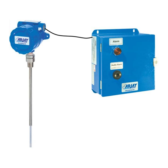
Rev: 2.1 INSTRUMENT OVERVIEW The Arjay Model 2852-LS Two Point Level Switch Alarm provides two independent alarm relays for monitoring and control of liquids or solids in a tank or vessel. The Arjay probe has an active capacitance probe that is inserted into the vessel. -
Page 4: Specifications
Model: 2852-LS User Manual Rev: 2.1 Specifications 12 VDC +15% /-10% or 24 VDC +15% /-10%, 250mA maximum Power Input: 100VAC – 240VAC +/- 10%, 50/60 Hz, 150mA maximum Note: DC input models must be supplied by Limited Energy power source. - Page 5 Model: 2852-LS User Manual Rev: 2.1 Equipment mobility Fixed Refer to Dimensional Drawing Mechanical Specification: Enclosure Rating Type 4 / IP65 Painted Steel (Blue) Type 4x / IP66 Polycarbonate (Gray) Type 4x / IP66 316 Stainless Steel Options on Enclosure...
-
Page 6: Installation
User Manual Rev: 2.1 INSTALLATION NOTE: If any damage to the instrument is found, please notify an Arjay Engineering representative as soon as possible prior to installation. Controller Installation Choose the mounting location in accordance with good instrument practice. Extremes of ambient temperature and vibration should be avoided (see specifications and installation drawing). -
Page 7: Probe Installation
Model: 2852-LS User Manual Rev: 2.1 Probe Installation The probe length is custom ordered to the tank or vessel requirements. On vertical and angled installations, the probe must be long enough to reach the lowest alarm setpoint. The PMC junction box should be mounted above any risk of flooding. -
Page 8: Figure 1 - Probe Installation
Model: 2852-LS User Manual Rev: 2.1 THREADED ENTRY FLANGED ENTRY CONCENTRIC SHIELD ENTRY Use wrench on Lower Hex ONLY 2" Entry Typical 1- For threaded and flanged entry types, the probe must be parallel to the tank wall 2- For threaded and flanged entry types, measurement sensitivity is increased by reducing the probe to wall distance. -
Page 9: Figure 2 - Typical Application
Model: 2852-LS User Manual Rev: 2.1 Figure 2 – Typical Application... -
Page 10: Electrical Installation
Model: 2852-LS User Manual Rev: 2.1 Electrical Installation Figure 3 – Electrical Installation Overview TB1/TB2 - Relay Output 2 SPDT relay, Dry, N.O. Contact 5A @ 250 VAC (Resistive) and N.C. Contact 3A @ 250VAC (Resistive), selectable failsafe or non-failsafe, selectable high or low acting alarm, programmable time delay: 0 –... -
Page 11: Input / Output Terminal Specification
Model: 2852-LS User Manual Rev: 2.1 2.3.1 Input / Output Terminal Specification Input Terminals – Power Source Terminal Overvoltage Rated Voltage (V) Rated ___ HZ or Specified category Current/power Mains (A/W/VA) fluctuation 100-240V 150mA 50/60Hz 12 OR 24V 250mA ... -
Page 12: Glossary Of Symbols
Model: 2852-LS User Manual Rev: 2.1 Glossary of Symbols Attention, consult accompanying documents Attention, veuillez consulter les documents ci-joints. Protective Earth Fuse Terre de protection Coupe-circuit; fusible Direct Current (DC) Normally open relay contacts Courant continu Contacts travail Normally closed relay contacts... -
Page 13: Startup And Calibration
The unit is pre-configured and tested at the factory. However, a quick field calibration is required after power up to tune the probe to the installation conditions. See section 3.3 to calibrate the 2852-LS . Menu Flow Chart Background Information The control setup, diagnostics, and calibration are accessed using the display and keypad on the controller. -
Page 14: Data Entry
Model: 2852-LS User Manual Rev: 2.1 Change is password protected and allows an operator to enter or change the configuration set- up values indicated in the View. Changes will be required for the initial setup of relay setpoints, delays, span etc. or to re-set the values to the factory default. - Page 15 This will get you back to the main menu of “CAL ONLY”. Press arrow down until you get to “EXIT” in order to get back to main screen OR go to “Change” if different relay configurations are required. THIS COMPLETES THE SETUP AND CALIBRATION PROCEDURE FOR THE 2852-LS Two Point Level Switch...
-
Page 16: Setup And Alarm
The factory default is 0 to provide an immediate and active response. 2852 Controller Alarms The two relays on the 2852-LS operate independently. They are named A1 and A2. The follow parameters are available to set up each of the relays. -
Page 17: Figure 4 - No Differential Application - High Level
Model: 2852-LS User Manual Rev: 2.1 Sample Of Single Point Alarms (No Differential) Applications ALARM POINT ABOVE CALIBRATION SETPOINTS ALARM POINT ABOVE CALIBRATION SETPOINTS ALARM CALIBRATION MODE: HIGH ^SP ALARM CALIBRATION MODE: HIGH ^SP -SENSITIVITY ADJUSTMENT depresses alarm point -SENSITIVITY ADJUSTMENT depresses alarm point i.e. -
Page 18: Figure 6 -Differential Application - Pumping Out
Model: 2852-LS User Manual Rev: 2.1 Sample Of Differential Applications SETTINGS: FAILSAFE: YES 2852-LS Alarm Above calibration point . PROCESS IN CONTACTS: USE COMMON (C) & NORMALLY CLOSED (NC) CONTACTS HIGH ALARM POINT LOW ALARM POINT PUMP ON PUMP OFF... -
Page 19: 2852 Controller Network
Model: 2852-LS User Manual Rev: 2.1 2852 Controller Network The 2852 Controller may be monitored and calibrated via RS-485 protocol compatible digital communications. Typical features are: 1. Ease of wiring in multiple level point monitoring: Up to 255 Model 2852's (or other Arjay 2800 Series level monitors) may be connected together... -
Page 20: 2800 Series Modbus Register Mapping
Model: 2852-LS User Manual Rev: 2.1 4.3.2 2800 Series Modbus Register Mapping Zero No. of Based DESCRIPTION TYPE 40001 Serial Number float 40003 Hardware Rev / Software Rev byte 40004 Sensitivity / Mode byte 40005 Instrument Status 40006 Model / Modbus Address... -
Page 21: Maintenance
Model: 2852-LS User Manual Rev: 2.1 MAINTENANCE There is no routine cleaning required for this controller. -
Page 22: Troubleshooting
Make sure there is no external interference and electrical noise such as agitators, high voltage interference, turbulent flow, etc Adjust the sensitivity to the next higher value. Test after any changes to confirm an alarm ARJAY ENGINEERING TECHNICAL SUPPORT (800) 387-9487 +1 (905) 829-2418 www.arjayeng.com... -
Page 23: Flow Charts
Model: 2852-LS User Manual Rev: 2.1 FLOW CHARTS... - Page 24 Model: 2852-LS User Manual Rev: 2.1...
- Page 25 Model: 2852-LS User Manual Rev: 2.1...
Need help?
Do you have a question about the 2852-LS and is the answer not in the manual?
Questions and answers