Table of Contents
Advertisement
Quick Links
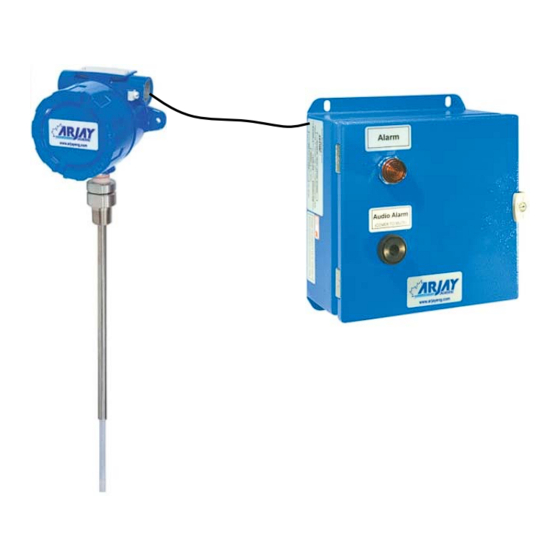
MODEL 2852-IFA
Liquid Interface Alarm Switch
User Manual
Technical Support
Continental North America Toll Free 1-(800) 387-9487
Ph: +1 (905) 829-2418 Fx: +1 (905) 829-4701
A Product of Arjay Engineering Ltd.
Oakville, Ontario, Canada
www.ArjayEng.com
MODEL:
HARDWARE NO.:
SOFTWARE NO.:
SERIAL NO.:
5.1
Advertisement
Table of Contents

Related Manuals for ARJAY ENGINEERING 2852-IFA


Summary of Contents for ARJAY ENGINEERING 2852-IFA
- Page 1 MODEL 2852-IFA Liquid Interface Alarm Switch User Manual Technical Support Continental North America Toll Free 1-(800) 387-9487 Ph: +1 (905) 829-2418 Fx: +1 (905) 829-4701 A Product of Arjay Engineering Ltd. Oakville, Ontario, Canada www.ArjayEng.com MODEL: HARDWARE NO.: SOFTWARE NO.:...
-
Page 2: Table Of Contents
Model: 2852-IFA User Manual Rev: 2.2 TABLE OF CONTENTS INSTRUMENT OVERVIEW .................... 3 Features ......................3 Model Number vs. Voltage Input ................ 3 Specifications ..................... 5 INSTALLATION ....................... 7 ... -
Page 3: Instrument Overview
Rev: 2.2 INSTRUMENT OVERVIEW The Arjay Model 2852-IFA Liquid Interface Alarm provides a means for detecting the change from one liquid to another liquid of a different dielectric, such as water to oil. The capacitance sensing probe can be submersed in any liquid type and in any vessel style such as a pipe, tank and pit. -
Page 4: Figure 1 - Typical Tank Application Overview
Model: 2852-IFA User Manual Rev: 2.2 Figure 1 – Typical Tank Application Overview Figure 2 – Typical Pipe Application Overview... -
Page 5: Specifications
Model: 2852-IFA User Manual Rev: 2.2 Specifications 12 VDC +15% /-10% or 24 VDC +15% /-10%, 250mA maximum Power Input: 100VAC – 240VAC +/- 10%, 50/60 Hz, 150mA maximum Note: DC input models must be supplied by Limited Energy power source. - Page 6 Model: 2852-IFA User Manual Rev: 2.2 Refer to Dimensional Drawing Mechanical Specification: Enclosure Rating Type 4 / IP65 Painted Steel (Blue) Type 4x / IP66 Polycarbonate (Gray) Type 4x / IP66 316 Stainless Steel Options on Enclosure Buzzer Pilot Light OR Strobe/Beacon Custom alarms ...
-
Page 7: Installation
User Manual Rev: 2.2 INSTALLATION NOTE: If any damage to the instrument is found, please notify an Arjay Engineering representative as soon as possible prior to installation. Controller Installation Choose the mounting location in accordance with good instrument practice. Extremes of ambient temperature and vibration should be avoided (see specifications and installation drawing). -
Page 8: Probe Installation
Model: 2852-IFA User Manual Rev: 2.2 Probe Installation The probe length is custom ordered to the vessel requirements. A minimum 50mm length is recommended. Longer probes will provide greater sensitivity to impending liquid changes. Probes top mounted into open tanks may require an inactive sheath to ensure the active probe portion is immersed in liquid at all times The PMC junction box should be mounted above the water surge level and in a protected area. -
Page 9: Electrical Installation
Model: 2852-IFA User Manual Rev: 2.2 Electrical Installation Figure 4 – Electrical Installation Overview TB1/TB2 - Relay Output 2 SPDT relay, Dry, N.O. Contact 5A @ 250 VAC (Resistive) and N.C. Contact 3A @ 250VAC (Resistive), selectable failsafe or non-failsafe, selectable high or low acting alarm, programmable time delay: 0 –... -
Page 10: Input / Output Terminal Specification
Model: 2852-IFA User Manual Rev: 2.2 2.3.1 Input / Output Terminal Specification Input Terminals – Power Source Terminal Overvoltage Rated Voltage (V) Rated ___ HZ or Specified category Current/power Mains (A/W/VA) fluctuation 100-240V 150mA 50/60Hz 12 OR 24V 250mA ... -
Page 11: Glossary Of Symbols
Model: 2852-IFA User Manual Rev: 2.2 Glossary of Symbols Attention, consult accompanying documents Attention, veuillez consulter les documents ci-joints. Protective Earth Fuse Terre de protection Coupe-circuit; fusible Direct Current (DC) Normally open relay contacts Courant continu Contacts travail Normally closed relay contacts... -
Page 12: Startup And Calibration
The unit is pre-configured and tested at the factory. However, a quick field calibration is required after power up to tune the probe to the installation conditions. See section 3.3 to calibrate the 2852-IFA . Menu Flow Chart Background Information The control setup, diagnostics, and calibration are accessed using the display and keypad on the controller. -
Page 13: Data Entry
Normal Normal Screen 3.3.1 Site Calibration A factory pre-configuration and basic set-up has been defaulted into the 2852-IFA but a field calibration is required after installation. Allow one hour warmup before proceeding to calibration. The unit can be set to alarm when a high dielectric liquid (High pF) changes to a low dielectric liquid (Low pF), such as water to oil, or when a low dielectric liquid changes to a high dielectric liquid such as oil to water. - Page 14 Model: 2852-IFA User Manual Rev: 2.2 If the calibration is successful, the display will return to the main operating display and show normal condition. THIS COMPLETES THE SETUP AND CALIBRATION PROCEDURE FOR THE 2852-IFA Liquid Interface Alarm Switch...
-
Page 15: Setup And Alarms
The factory default is 0 to provide an immediate and active response. 2852 Controller Alarms The two relays on the 2852-IFA operate together. The follow parameters are available as a common setting to the two relays: 1. Delay. Minimum time in seconds for an alarm to exist before the relays change to an alarm state. -
Page 16: 2852 Controller Network
Model: 2852-IFA User Manual Rev: 2.2 2852 Controller Network The 2852 Controller may be monitored and calibrated via RS-485 protocol compatible digital communications. Typical features are: 1. Ease of wiring in multiple level point monitoring: Up to 255 Model 2852's (or other Arjay 2800 Series level monitors) may be connected together... -
Page 17: 2800 Series Modbus Register Mapping
Model: 2852-IFA User Manual Rev: 2.2 4.3.2 2800 Series Modbus Register Mapping Zero No. of Based DESCRIPTION TYPE 40001 Serial Number float 40003 Hardware Rev / Software Rev byte 40004 Sensitivity / Mode byte 40005 Instrument Status 40006 Model / Modbus Address... -
Page 18: Maintenance
Model: 2852-IFA User Manual Rev: 2.2 MAINTENANCE There is no routine cleaning required for this controller. -
Page 19: Troubleshooting
Adjust the sensitivity to the next higher value. Test after any changes to confirm an alarm Make sure the active probe is immersed fully in liquid at all times. ARJAY ENGINEERING TECHNICAL SUPPORT (800) 387-9487 +1 (905) 829-2418 www.arjayeng.com... -
Page 20: Flow Charts
Model: 2852-IFA User Manual Rev: 2.2 FLOW CHARTS NORMAL OPERATING DISPLAY Normal Press <SELECT> Press & hold <MENU> Press < > Press < > Press < > Sel Mode Sel Mode Sel Mode Sel Mode Change Exit Cal only View Press <... - Page 21 Model: 2852-IFA User Manual Rev: 2.2 VIEW MENU Sel Mode View Press <SELECT> Press <SELECT> Press < > Press < > Press < > Press < > SELECT: SELECT: SELECT: SELECT: SELECT: Press < > Press < > Press <...
- Page 22 Model: 2852-IFA User Manual Rev: 2.2...
Need help?
Do you have a question about the 2852-IFA and is the answer not in the manual?
Questions and answers