Garmin ECHOMAP ULTRA Series Owner's Manual
Hide thumbs
Also See for ECHOMAP ULTRA Series:
- Installation instructions (4 pages) ,
- Installation instructions (4 pages) ,
- Owner's manual (52 pages)
Table of Contents
Advertisement
Quick Links
Advertisement
Table of Contents

Related Manuals for Garmin ECHOMAP ULTRA Series


Summary of Contents for Garmin ECHOMAP ULTRA Series
- Page 1 ECHOMAP ULTRA SERIES ™ Owner’s Manual...
- Page 2 © 2019 Garmin Ltd. or its subsidiaries All rights reserved. Under the copyright laws, this manual may not be copied, in whole or in part, without the written consent of Garmin. Garmin reserves the right to change or improve its products and to make changes in the content of this manual without obligation to notify any person or organization of such changes or improvements. Go to www.garmin.com...
-
Page 3: Table Of Contents
Mapping a Body of Water Using the ActiveCaptain Roles........ 7 Garmin Quickdraw Contours Feature.. 26 Getting Started with the ActiveCaptain Adding a Label to a Garmin Quickdraw App............8 Contours Map........26 Enabling Smart Notifications....8 Garmin Quickdraw Community.... 26 Receiving Notifications....... - Page 4 Split-Zoom Sonar View..... 48 Saving the Active Track....39 Flasher View.......... 49 Viewing a List of Saved Tracks..39 Flasher Page Shortcuts..... 50 Editing a Saved Track....... 39 Garmin ClearVü Sonar View....51 Saving a Track as a Route....39 Table of Contents...
- Page 5 Garmin SideVü™ Sonar View....52 Panoptix Transducer Installation Settings..........72 SideVü Scanning Technology... 53 Measuring Distance on the Sonar Autopilot........74 Screen..........53 Panoptix Sonar Views......53 Autopilot Screen........74 LiveVü Down Sonar View....54 Adjusting the Step Steering LiveVü Forward Sonar View....55 Increment...........
- Page 6 Resetting Trip Gauges.......81 Digital Switching......90 Viewing Engine and Fuel Gauges..82 Adding and Editing a Digital Switching Engine Alert Icons......82 Page............90 Selecting the Number of Engines Shown in Gauges....... 82 Tide, Current, and Celestial Customizing the Engines Shown in Information........
- Page 7 Viewing the Event Log....101 ActiveCaptain and Garmin Express... 112 Viewing System Software Garmin Express App......112 Information........102 Installing the Garmin Express App on a Viewing E-label Regulatory and Computer......... 112 Compliance Information....102 Registering Your Device Using the My Vessel Settings......
- Page 8 My sonar does not work....117 My device is not creating waypoints in the correct location......117 My device does not display the correct time..........117 Garmin Support Center....... 117 Specifications........118 All Models........118 10-Inch Models........ 118 12-Inch Models........ 119 Sonar Models Specifications..
-
Page 9: Introduction
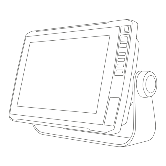
Introduction WARNING See the Important Safety and Product Information guide in the product box for product warnings and other important information. Front View Automatic backlight sensor Power key Zoom keys Shortcut keys Touchscreen 2 microSD memory card slots; 32 GB max. card size ®... -
Page 10: Connector View
LVS12 12-pin transducer ™ ™ NMEA 2000 NMEA 2000 ® network Panoptix LiveScope sonar or Garmin ® Marine Network for sharing sonar, charts, and user NETWORK data Ground screw NOTICE To prevent corrosion of the metal contacts, cover unused connectors with weather caps. -
Page 11: Tips And Shortcuts
, and select Power > Sleep Device to set the chartplotter to standby mode, when available. Accessing the Manuals from the Web You can get the latest owner's manual and translations of manuals from the Garmin website. The owner's manual includes instructions for using device features and accessing regulatory information. -
Page 12: Acquiring Gps Satellite Signals
If the device loses satellite signals, a flashing question mark appears over the boat position indicator ( ) on the chart. For more information about GPS, go to garmin.com/aboutGPS. For help acquiring satellite signals, see device will not acquire GPS signals, page 116). -
Page 13: Customizing Pages
Customizing Pages Creating a New Combination Page with the ECHOMAP Ultra You can create a custom combination page to suit your needs. 1 Select Combos > Customize > Add. 2 Select a layout. 3 Select an area. 4 Select a function for the area. 5 Repeat these steps for each area of the page. -
Page 14: Customizing The Data Overlays
Customizing the Data Overlays You can customize the data in the data overlays shown on a screen. 1 Select an option based on the type of screen you are viewing: • From a full screen view, select Menu > Edit Overlays. •... -
Page 15: Changing The Background Image
ActiveCaptain App WARNING This feature allows users to submit information. Garmin makes no representations about the accuracy, completeness, or timeliness of information submitted by users. Any use or reliance on the information submitted by users is at your own risk. -
Page 16: Getting Started With The Activecaptain App
5 From the application store on your mobile device, install and open the ActiveCaptain app. 6 Bring the mobile device within 32 m (105 ft.) of the ECHOMAP Ultra device. 7 From your mobile device settings, open the Wi‑Fi connections page and connect to the Garmin device, using ® the name and password you entered. -
Page 17: Receiving Notifications
Receiving Notifications WARNING Do not read or reply to notifications while operating the vessel. Failure to pay attention to the conditions on the water can result in vessel damage, personal injury, or death. Before your ECHOMAP Ultra device can receive notifications, you must connect it to your mobile device and enable the Smart Notifications feature. -
Page 18: Updating Software With The Activecaptain App
After you download a chart or area for the first time, updates are automatic each time you open ActiveCaptain. If you are downloading an entire chart, you can use the Garmin Express app to download the map onto ™... -
Page 19: Charts And 3D Chart Views
Charts and 3D Chart Views The charts and 3D chart views that are available depend on the map data and accessories used. NOTE: 3D chart views are available with premium charts, in some areas. You can access the charts and 3D chart views by selecting Charts. Navigation Chart: Shows navigation data available on your pre-loaded maps and from supplemental maps, if available. -
Page 20: Chart Symbols
Chart Symbols This table contains some of the common symbols you might see on the detailed charts. Icon Description Buoy Information Marine services Tide station Current station Overhead photo available Perspective photo available Other features common to most charts include depth contour lines, intertidal zones, spot soundings (as depicted on the original paper chart), navigational aids and symbols, obstructions, and cable areas. -
Page 21: Navigating To A Point On The Chart
Navigating to a Point on the Chart WARNING All route and navigation lines displayed on the chartplotter are only intended to provide general route guidance or to identify proper channels, and are not intended to be precisely followed. Always defer to the navaids and conditions on the water when navigating to avoid groundings or hazards that could result in vessel damage, personal injury, or death. -
Page 22: Heading Line And Angle Markers
Heading Line and Angle Markers The heading line is an extension drawn on the map from the bow of the boat in the direction of travel. Angle markers indicate relative position from the heading or course over ground, which are helpful for casting or finding reference points. -
Page 23: Premium Charts
Carefully compare the course to all visual sightings, and avoid any land, shallow water, or other obstacles that may be in your path. NOTE: Not all models support all charts. Optional premium charts, such as Garmin Navionics Vision+ , allow you to get the most out of your chartplotter. ™... -
Page 24: Showing Satellite Imagery On The Navigation Chart
Animated Tide and Current Indicators WARNING Tide and current information is for information purposes only. It is your responsibility to heed all posted water-related guidance, to remain aware of your surroundings, and to use safe judgment in, on, and around the water at all times. -
Page 25: Viewing Aerial Photos Of Landmarks
Viewing Aerial Photos of Landmarks Before you can view aerial photos on the Navigation chart, you must turn on the Photo Points setting in the chart setup (Chart Layers, page 22). NOTE: This feature is available with premium charts, in some areas. You can use aerial photographs of landmarks, marinas, and harbors to help orient yourself to your surroundings or to acquaint yourself with a marina or a harbor prior to arrival. -
Page 26: Heading And Projected Course Of Activated Ais Targets
NOTE: Vessels being tracked with the Blue Force Tracking feature are indicated with a blue-green color regardless of their status. Heading and Projected Course of Activated AIS Targets When heading and course over ground information are provided by an activated AIS target, the heading of the target appears on a chart as a solid line attached to the AIS target symbol. -
Page 27: Setting The Safe-Zone Collision Alarm
Setting the Safe-Zone Collision Alarm WARNING This feature is a tool for situational awareness only and may not prevent groundings or collisions in all circumstances. It is your obligation to ensure safe operation of your vessel. CAUTION The Beeper setting must be turned on to make alarms audible (System Settings, page 101). -
Page 28: Ais Distress Signals
Symbol Meaning Real or synthetic ATON Real or synthetic ATON: Topmark North Real or synthetic ATON: Topmark South Real or synthetic ATON: Topmark East Real or synthetic ATON: Topmark West Real or synthetic ATON: Topmark Special Real or synthetic ATON: Topmark Safe Real or synthetic ATON: Topmark Danger Virtual ATON Virtual ATON: Topmark North... -
Page 29: Chart Menu
(User Data Layer Settings, page 23). Quickdraw Contours: Turns on bottom contour drawing, and allows you to create fishing map labels (Garmin Quickdraw Contours Mapping, page 25). Chart Setup: Adjusts the orientation and level of detail shown on the chart and adjusts the data shown on the screen. -
Page 30: Chart Layers
(Other Vessels Layer Settings, page 23). Water: Shows and hides depth items (Water Layer Settings, page 24). Quickdraw Contours: Shows and hides Garmin Quickdraw Contours data (Garmin Quickdraw Contours Settings, page 28). Chart Layer Settings From a chart, select Menu > Layers > Chart. - Page 31 Laylines Settings To use the laylines features, you must connect a wind sensor to the chartplotter. When in sailing mode (Setting the Vessel Type, page 6), you can display laylines on the navigation chart. Laylines can be very helpful when racing. From the Navigation chart, select Menu >...
- Page 32 For inland fishing, a maximum of five depth ranges can help reduce map clutter. The depth ranges apply to all charts and all bodies of water. Some Garmin LakeVü and premium supplemental charts have multiple depth range shading by default.
-
Page 33: Fish Eye 3D Settings
1,500 hours of data onto a 2 GB memory card. When you record data on a memory card in your chartplotter, the new data is added to your existing Garmin Quickdraw Contours map, and is saved on the memory card. When you insert a new memory card, the existing data does not transfer onto the new card. -
Page 34: Mapping A Body Of Water Using The Garmin Quickdraw Contours Feature
Mapping a Body of Water Using the Garmin Quickdraw Contours Feature Before you can use the Garmin Quickdraw Contours feature, you must have sonar depth, your GPS position, and a memory card with free space. 1 From a chart view, select Menu > Quickdraw Contours > Start Recording. -
Page 35: Connecting To The Garmin Quickdraw Community With Garmin Connect
Sharing Your Garmin Quickdraw Contours Maps with the Garmin Quickdraw Community Using ActiveCaptain You can share Garmin Quickdraw Contours maps that you have created with others in the Garmin Quickdraw Community. When you share a contour map, only the contour map is shared. Your waypoints are not shared. -
Page 36: Garmin Quickdraw Contours Settings
Survey Coloring: Sets the color of the Garmin Quickdraw Contours display. When this setting is turned on, the colors indicate the quality of the recording. When this setting is turned off, the contour areas use standard map colors. -
Page 37: Navigation With A Chartplotter
Navigation with a Chartplotter WARNING All route and navigation lines displayed on the chartplotter are only intended to provide general route guidance or to identify proper channels, and are not intended to be precisely followed. Always defer to the navaids and conditions on the water when navigating to avoid groundings or hazards that could result in vessel damage, personal injury, or death. -
Page 38: Basic Navigation Questions
For example, the roue segment is red striped when the route crosses under a very low bridge or is in shallow waters. This line is red striped in Garmin Navionics+ and Garmin Navionics Vision+ charts only; it is magenta and gray striped in previous versions of the charts. -
Page 39: Searching For A Destination By Name
Searching for a Destination by Name You can search for saved waypoints, saved routes, saved tracks, and marine services destinations by name. 1 Select Nav Info > Search by Name. 2 Enter at least a portion of the name of your destination. 3 If necessary, select Done. -
Page 40: Marking Your Present Location As A Waypoint
Marking Your Present Location as a Waypoint From any screen, select Mark. Creating a Waypoint at a Different Location 1 From a chart, select Nav Info > Waypoints > New Waypoint. 2 Select an option: • To create the waypoint by entering position coordinates, select Enter Coordinates, and enter the coordinates. -
Page 41: Moving A Saved Waypoint
Moving a Saved Waypoint 1 Select Nav Info > Waypoints. 2 Select a waypoint. 3 Select Review > Edit > Position. 4 Indicate a new location for the waypoint: • To move the waypoint using coordinates, select Enter Coordinates, enter the new coordinates, and select Done or Cancel. -
Page 42: Routes
Routes A route is a path from one location to one or more destinations. Creating and Navigating a Route From Your Present Location You can create and immediately navigate a route on the Navigation chart or the Fishing chart. This method does not save the route. -
Page 43: Browsing For And Navigating A Saved Route
Browsing for and Navigating a Saved Route Before you can browse a list of routes and navigate to one of them, you must create and save at least one route. 1 Select Nav Info > Routes. 2 Select a route. 3 Select Navigate To. -
Page 44: Auto Guidance
Auto Guidance WARNING The Auto Guidance feature is based on electronic chart information. That data does not ensure obstacle and bottom clearance. Carefully compare the course to all visual sightings, and avoid any land, shallow water, or other obstacles that may be in your path. All route and navigation lines displayed on the chartplotter are only intended to provide general route guidance or to identify proper channels, and are not intended to be precisely followed. -
Page 45: Canceling An Auto Guidance Calculation In Progress
Clearance settings, the section of the Auto Guidance path appears as a solid orange line or a red striped line in Garmin Navionics+ and Garmin Navionics Vision+ charts and appears as a magenta and gray striped line in previous versions. When your boat enters one of those areas, a warning message appears (Route Color Coding, page 30). -
Page 46: Tracks
Adjusting the Distance from Shore The Shoreline Distance setting indicates how close to the shore you want the Auto Guidance line to be placed. The Auto Guidance line may move if you change this setting while navigating. The available values for the Shoreline Distance setting are relative, not absolute. -
Page 47: Saving The Active Track
Saving the Active Track The track currently being recorded is called the active track. 1 Select Nav Info > Tracks > Save Active Track. 2 Select an option: • Select the time the active track began. • Select Entire Log. 3 Select Save. -
Page 48: Retracing The Active Track
Retracing the Active Track The track currently being recorded is called the active track. 1 Select Nav Info > Tracks > Follow Active Track. 2 Select an option: • Select the time the active track began. • Select Entire Log. 3 Review the course indicated by the colored line. -
Page 49: Creating A Boundary
Creating a Boundary 1 Select Nav Info > Boundaries > New. 2 Select a boundary shape. 3 Follow the on-screen instructions. Converting a Route to a Boundary 1 Select Nav Info > Routes. 2 Select a route. 3 Select Review > Edit Route > Save as Boundary. Converting a Track to a Boundary 1 Select Nav Info >... -
Page 50: Sailing Features
Sailing Features Setting the Vessel Type for Sailing Features You must select a sailing vessel type to use the sailing features. 1 Select Settings > My Vessel > Vessel Type. 2 Select Sailboat or Sailing Catamaran. Sail Racing You can use the device to increase the likelihood that your boat will cross the start line of a race exactly when the race begins. -
Page 51: Setting The Distance Between The Bow And The Gps Antenna
Setting the Distance between the Bow and the GPS Antenna You can enter the distance between the bow of your boat and the location of your GPS antenna. This helps ensure the bow of your boat crosses the starting line at the precise start time. 1 From the starting line guidance gauge, select Menu >... -
Page 52: Setting The Keel Offset
Setting the Keel Offset You can enter a keel offset to compensate the water depth reading for the transducer installation location. This allows you to view the depth of the water below the keel or the true depth of the water, depending on your needs. -
Page 53: Sailboat Autopilot Operation
Sailboat Autopilot Operation WARNING You are responsible for the safe and prudent operation of your vessel. The autopilot is a tool that enhances your capability to operate your boat. It does not relieve you of the responsibility of safely operating your boat. Avoid navigational hazards and never leave the helm unattended CAUTION When engaged, the autopilot controls only the rudder. -
Page 54: Heading Line And Angle Markers
Tacking and Gybing from Wind Hold Before you can engage wind hold, you must have a wind sensor installed. 1 Engage wind hold (Engaging Wind Hold, page 45). 2 Select Menu. 3 Select an option. The autopilot steers your boat through a tack or gybe, and information about the progress of the tack or gybe appears on the screen. -
Page 55: Viewing Sailing Vessel Data
When properly connected to a compatible transducer, your chartplotter can be used as a fishfinder. For more information about which transducer is best for your needs, go to garmin.com/transducers. Different sonar views can help you view the fish in the area. The sonar views available vary depending on the type of transducer and sounder module connected to the chartplotter. -
Page 56: Traditional Sonar View
Traditional Sonar View There are several full-screen views available, depending on the transducer that is connected. The full-screen Traditional sonar view shows a large image of the sonar readings from a transducer. The range scale along the right side of the screen shows the depth of detected objects as the screen scrolls from the right to the left. -
Page 57: Flasher View
Flasher View The flasher shows sonar information on a circular depth scale, indicating what is beneath your boat. It is organized as a ring that starts at the top and progresses clockwise. Depth is indicated by the scale inside the ring. -
Page 58: Flasher Page Shortcuts
Flasher Page Shortcuts On touchscreen devices, you can interact with the flasher and a-scopes. Drag up and down to move the zoom area. Select to adjust the range. Select to adjust the frequency. Select to adjust the gain. Select to adjust the beam width. Drag the zoom window to move the zoom area on the left A-scope. -
Page 59: Garmin Clearvü Sonar View
NOTE: To receive Garmin ClearVü scanning sonar, you need a compatible transducer. For information about compatible transducers, go to garmin.com/transducers. Garmin ClearVü high-frequency sonar provides a detailed picture of the fishing environment around the boat in a detailed representation of structures the boat is passing over. -
Page 60: Garmin Sidevü™ Sonar View
Sonar View ™ Not all models provide built-in Garmin SideVü sonar support. If your model does not provide built-in SideVü sonar, you need a compatible sounder module and compatible SideVü transducer. If your model does provide built-in SideVü sonar, you need a compatible SideVü transducer. -
Page 61: Sidevü Scanning Technology
SideVü Scanning Technology Instead of a more common conical beam, the SideVü transducer uses a flat beam to scan the water and bottom to the sides of your boat. Measuring Distance on the Sonar Screen You can measure the distance between two points on the SideVü sonar view. 1 From the SideVü... -
Page 62: Livevü Down Sonar View
LiveVü Down Sonar View This sonar view shows a two-dimensional view of what is below the boat and can be used to see a bait ball and fish. Panoptix down view history in a scrolling sonar view Boat Range Trails Drop shot rig Bottom Sonar Fishfinder... -
Page 63: Livevü Forward Sonar View
LiveVü Forward Sonar View This sonar view shows a two-dimensional view of what is in front of the boat and can be used to see a bait ball and fish. Boat Range Fish Trails Bottom Sonar Fishfinder... -
Page 64: Realvü 3D Forward Sonar View
RealVü 3D Forward Sonar View This sonar view shows a three-dimensional view of what is in front of the transducer. This view can be used when you are stationary and you need to see the bottom and the fish approaching the boat. Color legend Boat Ping indicator... -
Page 65: Realvü 3D Down Sonar View
RealVü 3D Down Sonar View This sonar view shows a three-dimensional view of what is below the transducer and can be used when you are stationary and want to see what is around your boat. Color legend Boat Sonar beam Range Fish Bottom... -
Page 66: Realvü 3D Historical Sonar View
RealVü 3D Historical Sonar View This sonar view provides a three-dimensional view of what is behind your boat as you are moving and shows the entire water column in 3D, from the bottom to the top of the water. This view is used for finding fish. Color legend Boat Range... -
Page 67: Frontvü Sonar View
FrontVü Sonar View The Panoptix FrontVü sonar view increases your situational awareness by showing obstructions under the water, up to 91 meters (300 feet) in front of the boat. The ability to effectively avoid forward collisions with FrontVü sonar decreases as your speed rises above 8 knots. -
Page 68: Perspective View
To see this sonar view, you must install a compatible LiveScope transducer on compatible a perspective mode mount. Selecting the Transducer Type This chartplotter is compatible with a range of accessory transducers, including the Garmin ClearVü ™ transducers, which are available at garmin.com/transducers. -
Page 69: Calibrating The Compass
When you are using more than one sonar data source for a particular sonar view, you can select the source to use for that sonar view. For example, if you have two sources for Garmin ClearVü, you can select the source to use from the Garmin ClearVü... -
Page 70: Viewing Sonar History
2 Select Back to exit. Sonar Sharing You can view the sonar data from all compatible sources on the Garmin Marine Network. You can view sonar data from a compatible external sonar module, such as a GCV sonar module. In addition, you can view the ™... -
Page 71: Adjusting The Color Intensity
• To increase or decrease the color intensity manually, select Up or Down. • To use the default setting, select Default. Traditional, Garmin ClearVü, and SideVü Sonar Setup NOTE: Not all options and settings apply to all models and transducers. -
Page 72: Setting The Scroll Speed
• To scroll more slowly, select Down. Adjusting the Range You can adjust the range of the depth scale for traditional and Garmin ClearVü sonar views. You can adjust the range of the width scale for the SideVü sonar view. -
Page 73: Sonar Appearance Settings
Sonar Appearance Settings From a sonar view, select Menu > Sonar Setup > Appearance. Color Scheme: Sets the color scheme. A-Scope: Displays a vertical flasher along the right side of the screen that shows instantaneously the range to targets along a scale. Edge: Highlights the strongest signal from the bottom to help define the hardness or softness of the signal. -
Page 74: Advanced Sonar Settings
Advanced Sonar Settings NOTE: Not all options and settings apply to all views and transducers. From a sonar view, select Menu > Sonar Setup > Advanced. Interference: Adjusts the sensitivity to reduce the effects of interference from nearby sources of noise. The lowest interference setting that achieves the desired improvement should be used to remove interference from the screen. -
Page 75: Sonar Frequencies
Sonar Frequencies NOTE: The frequencies available depend on the transducers being used. Adjusting the frequency helps adapt the sonar for your particular goals and the present depth of the water. Higher frequencies use narrow beam widths, and are better for high-speed operation and rough sea conditions. Bottom definition and thermocline definition can be better when using a higher frequency. -
Page 76: Turning On The A-Scope
Turning On the A-Scope NOTE: This feature is available in the Traditional sonar views. The a-scope is a vertical flasher along the right side of the view, showing you what is underneath the transducer right now. You can use the a-scope to identify target returns that may be missed when the sonar data is quickly scrolling across the screen, such as when your boat is moving at high speeds. -
Page 77: Livevü Forward And Frontvü Sonar Settings
LiveVü Forward and FrontVü Sonar Settings From the LiveVü Forward or FrontVü sonar view, select Menu. Gain: Controls the level of detail and noise shown on the sonar screen. If you want to see the highest intensity signal returns on the screen, you can lower the gain to remove lower intensity returns and noise. -
Page 78: Livevü And Frontvü Appearance Settings
Setting the FrontVü Depth Alarm WARNING FrontVü sonar and the FrontVü depth alarm are tools for situational awareness only, and may not prevent groundings in all circumstances. As vessel speeds approach and exceed 8 knots, your ability to effectively respond to the information provided by the sonar and/or alarm decreases. It is your responsibility to remain aware of your surroundings while underway and to operate your vessel in a safe and prudent manner. -
Page 79: Livescope And Perspective Sonar Settings
LiveScope and Perspective Sonar Settings From the LiveScope or Perspective sonar view, select Menu. Gain: Controls the level of detail and noise shown on the sonar screen. If you want to see the highest intensity signal returns on the screen, you can lower the gain to remove lower intensity returns and noise. -
Page 80: Panoptix Transducer Installation Settings
LiveScope and Perspective Appearance Settings From the LiveScope or Perspective sonar view, select Menu > Sonar Setup > Appearance. Color Scheme: Sets the color palette. Color Gain: Adjusts the contrast of colors shown on the screen. You can select a higher color gain value to see minor variances in targets with large color changes. You can select a lower color gain value to see more similar colors in the same situation. - Page 81 Setting the Bow Offset For forward view Panoptix transducers, you can enter a bow offset to compensate the forward distance readings for the transducer installation location. This allows you to view the forward distance from the bow instead of the transducer installation location. This feature applies to Panoptix transducers in the FrontVü, LiveVü...
-
Page 82: Autopilot
The autopilot system continuously adjusts the steering of your boat to maintain a constant heading (heading hold). The system also allows manual steering and several modes of automatic-steering functions and patterns. When the chartplotter is connected to a compatible Garmin autopilot system, you can engage and control the autopilot from the chartplotter. -
Page 83: Setting The Power Saver
Setting the Power Saver You can adjust the level of rudder activity. 1 From the autopilot screen, select Menu > Autopilot Setup > Power Mode Setup > Power Saver. 2 Select a percentage. Selecting a higher percentage reduces rudder activity and heading performance. The higher the percentage, the more the course deviates before the autopilot corrects it. -
Page 84: Adjusting The Heading With The Chartplotter In Step Steering Mode
Adjusting the Heading with the Chartplotter in Step Steering Mode 1 Engage a heading hold (Engaging the Autopilot, page 75). 2 Select an option: • Select <1° or 1°> to initiate a single 1° turn. • Select <<10° or 10°>> to initiate a single 10° turn. •... -
Page 85: Reactor™ Autopilot Remote Control
You can wirelessly connect a Reactor autopilot remote control to the chartplotter to control the compatible Reactor autopilot system. For more information about using the remote, see the Reactor autopilot remote control instructions at garmin .com Pairing a Reactor Autopilot Remote Control With a Chartplotter 1 Select Menu >... -
Page 86: Connecting To A Trolling Motor
Connecting to a Trolling Motor You can connect the chartplotter wirelessly to a compatible Garmin Force trolling motor on your boat to control the trolling motor from the chartplotter. 1 Turn on the chartplotter and the trolling motor. 2 Enable the Wi‑Fi network on the chartplotter (Setting Up the Wi‑Fi Wireless Network,... -
Page 87: Trolling Motor Control Bar
Trolling Motor Control Bar The trolling motor control bar allows you to control a Force trolling motor and see the status of the motor. Select an item to engage it. The button illuminates when selected. Select the item again to disengage it. Trolling motor battery status. -
Page 88: Trolling Motor Settings
Trolling Motor Settings From the trolling motor bar, select Calibrate: Calibrates the trolling motor compass (Calibrating the Trolling Motor Compass, page 80) and sets the trolling motor bow offset (Setting the Bow Offset, page 81). Anchor Gain: Sets the response of the trolling motor when in anchor lock mode. If you need the trolling motor to be more responsive and move quicker, increase the value. -
Page 89: Setting The Bow Offset
Setting the Bow Offset Based on the installation angle, the trolling motor may not align with the center line of your boat. For the best results, you should set the bow offset. 1 Adjust the angle of the trolling motor so it aligns with the center line of your boat , pointing straight forward. -
Page 90: Viewing Engine And Fuel Gauges
Viewing Engine and Fuel Gauges Before you can view engine and fuel gauges, you must be connected to a NMEA 2000 network capable of sensing engine and fuel data. See the installation instructions for details. Select Gauges > Engine. Engine Alert Icons If an icon lights up on the gauges page, it indicates an issue with the motor. -
Page 91: Enabling Some Engine Gauge Status Alarms
Enabling Some Engine Gauge Status Alarms 1 From the engine gauges screen, select Menu > Gauge Setup > Status Alarms > Custom. 2 Select one or more engine gauge alarms to turn on or off. Setting the Fuel Alarm CAUTION The Beeper setting must be turned on to make alarms audible (System Settings, page 101). -
Page 92: Configuring The Heading Source Of The Wind Gauge
Configuring the Heading Source of the Wind Gauge You can specify the source of the heading displayed on the wind gauge. Magnetic heading is the heading data received from a heading sensor, and GPS heading is calculated by your chartplotter GPS (course over ground). 1 From the wind gauge, select Menu >... -
Page 93: Controlling Third-Party Equipment Installed On Your Boat
Engine voltage or Mercury Steering Angle Boat status Boat speed Fuel Transmission gear Engine speed Trim tabs Engine trim TIP: To view additional engine details, select Menu > Engine Data. Controlling Third-Party Equipment Installed on Your Boat Power-Pole Anchor System ®... -
Page 94: Setting Up The Power-Pole Anchor
Setting Up the Power-Pole Anchor Before you can use the chartplotter to control the Power-Pole anchor, you must select the required installation mode. The default initial installation mode setting is None. While the installation mode is set to None, the chartplotter control of the Power-Pole anchor(s) is inactive. -
Page 95: Enabling The Mercury Helm
Enabling the Mercury Helm WARNING You are responsible for the safe and prudent operation of your vessel. The Mercury Helm does not steer the boat for you and does not avoid navigational hazards. Failure to safely operate your boat could result in an accident causing property damage, serious personal injury, or death. -
Page 96: Mercury Troll Overlay
Mercury Troll Overlay When connected to a compatible Mercury engine, you can use the Mercury Troll overlay on the chartplotter to set a target speed. Select to decrease the target speed Target speed Select to increase the target speed Actual speed Enable Select to engage the Mercury Troll feature Disable... -
Page 97: Mercury Cruise Control Overlay
Mercury Cruise Control Overlay Select to decrease the target speed Target speed Select to increase the target speed Actual speed Enable Select to engage the cruise control Disable Select to disengage the cruise control Mercury Engine Details WARNING You are responsible for the maintenance of the engines on your vessel. Failure to properly maintain the engines could result in an accident causing property damage, serious personal injury, or death. -
Page 98: Mercury Engine Overlay
For example, you can control the interior lights and navigation lights on the vessel. You can also monitor live well circuits. For more information about purchasing and configuring a digital switching system, contact your Garmin dealer. Adding and Editing a Digital Switching Page You can add and customize digital switching pages on the chartplotter. -
Page 99: Tide, Current, And Celestial Information
Tide, Current, and Celestial Information Tide Station Information WARNING Tide and current information is for information purposes only. It is your responsibility to heed all posted water-related guidance, to remain aware of your surroundings, and to use safe judgment in, on, and around the water at all times. -
Page 100: Digital Selective Calling
Digital Selective Calling Chartplotter and NMEA 0183 VHF Radio Functionality When your chartplotter is connected to a NMEA 0183 VHF radio, these features are enabled. • The chartplotter can transfer your GPS position to your radio. If your radio is capable, GPS position information is transmitted with DSC calls. -
Page 101: Viewing A Position Report
Individual Routine Calls When you connect the chartplotter to a Garmin VHF radio, you can use the chartplotter interface to set up an individual routine call. When setting up an individual routine call from your chartplotter, you can select the DSC channel on which you want to communicate. -
Page 102: Selecting A Dsc Channel
As long as you have one of the networked Fusion stereos connected to the NMEA 2000 network or the Garmin Marine Network, the chartplotter should automatically detect the stereos. -
Page 103: Media Player Icons
Media Player Icons NOTE: Not all devices have these icons. Icon Description Saves or deletes a channel as a preset Repeats all songs Repeats one song Scans for stations Searches for stations or skips songs Shuffles Selecting the Media Device and Source You can select the media source connected to the stereo. -
Page 104: Adjusting The Volume
Adjusting the Volume Enabling and Disabling Zones If you have wired your vessel's speakers into zones, you can enable needed zones and disable unused zones. 1 From the media screen, select Menu > Audio Levels > Enable/Disable Zones. 2 Select a zone. Muting the Media Volume 1 From the media screen, select 2 If necessary, select Select Position. -
Page 105: Changing The Tuning Mode
Changing the Tuning Mode You can change how you select a station for some media types, such as FM or AM radio. NOTE: Not all tuning modes are available for all media sources. 1 From the media screen, select Menu > Tuning Mode. 2 Select an option. -
Page 106: Changing Dab Stations
Changing DAB Stations 1 Select the DAB source. 2 If necessary, select Scan to scan for local DAB stations. 3 Select to change the station. When you reach the end of the current ensemble, the stereo automatically changes to the first available station in the next ensemble. -
Page 107: Activating A Siriusxm Subscription
Activating a SiriusXM Subscription 1 With the SiriusXM source selected, tune to channel 1. You should be able to hear the preview channel. If not, check the SiriusXM Connect Tuner and antenna installation and connections, and try again. 2 Tune to channel 0 to locate the Radio ID. 3 Contact SiriusXM listener care by phone at (866) 635-2349 or go to www.siriusxm.com/activatenow subscribe in the United States. -
Page 108: Setting The Device Name
3 Select Select Position or Done. Updating the Media Player Software You can update the software on compatible connected stereos and accessories. See the stereo Owner's Manual at support.garmin.com for instructions on updating the software. Device Configuration Turning On the Chartplotter Automatically You can set the chartplotter to turn on automatically when the power is applied. -
Page 109: System Settings
System Settings Select Settings > System. Display: Adjusts the backlight brightness and color scheme. Beeper: Turns on and off the tone that sounds for alarms and selections. Satellite Positioning: Provides information about the GPS satellite settings and fix. Auto Power Up: Turns on the device automatically when power is applied (Turning On the Chartplotter Automatically, page 100). -
Page 110: Viewing System Software Information
Viewing System Software Information You can view the software version, the basemap version, all supplemental map information (if applicable), and the unit ID number. You may need this information to update the system software or to purchase additional map data information. Select Settings >... -
Page 111: Setting The Keel Offset
Setting the Keel Offset You can enter a keel offset to compensate the water depth reading for the transducer installation location. This allows you to view the depth of the water below the keel or the true depth of the water, depending on your needs. -
Page 112: Setting The Water Temperature Offset
Setting the Water Temperature Offset The temperature offset compensates for the temperature reading from a temperature sensor or temperature- capable transducer. 1 Measure the water temperature using the temperature sensor or temperature-capable transducer that is connected to the network. 2 Measure the water temperature using a different temperature sensor or a thermometer that is known to be accurate. -
Page 113: Communications Settings
Serial Port: Sets the input/output format for the serial port to use when connecting the chartplotter to external NMEA devices, computers, or other Garmin devices. The Garmin Data Transfer option is used when connecting to a computer. The NMEA Standard option is used when connecting to a DSC VHF radio. The NMEA High Speed is used when connecting to an AIS VHF radio. -
Page 114: Wi-Fi Network
Naming Devices and Sensors on the Network You can name devices and sensors connected to the Garmin Marine Network and the NMEA 2000 network. 1 Select Settings > Communications. 2 Select Marine Network or NMEA 2000 Setup > Device List. -
Page 115: System Alarms
System Alarms Select Settings > Alarms > System. Device Voltage: Sets an alarm to sound when the battery reaches a specified low voltage. GPS Accuracy: Sets an alarm to sound when the GPS location accuracy falls outside the user-defined value. Sonar Alarms WARNING The sonar alarms feature is a tool for situational awareness only and may not prevent grounding in all... -
Page 116: Setting The Safe-Zone Collision Alarm
Setting the Safe-Zone Collision Alarm WARNING This feature is a tool for situational awareness only and may not prevent groundings or collisions in all circumstances. It is your obligation to ensure safe operation of your vessel. CAUTION The Beeper setting must be turned on to make alarms audible (System Settings, page 101). -
Page 117: Navigation Settings
• To clear saved data and reset device settings to the factory default values, disconnect the chartplotter from the Garmin Marine Network, and select Delete Data and Reset Settings. This does not affect maps or software updates. Sharing and Managing User Data WARNING This feature allows you to import data from other devices that may have been generated by third parties. -
Page 118: Selecting A File Type For Third-Party Waypoints And Routes
(Inserting Memory Cards, page 3). 2 Open the Garmin Express application. If you do not have the Garmin Express application installed on your computer, you can download it from garmin.com/express. 3 If necessary, register your device (Registering Your Device Using the Garmin Express App, page 113). -
Page 119: Backing Up Data To A Computer
1 Insert a memory card into a card reader that is attached to the computer. 2 Copy a backup file from the computer to the memory card, into a folder named Garmin\UserData. 3 Insert a memory card into the card slot. -
Page 120: Appendix
Receive smart notification on the chartplotter Garmin Express App The Garmin Express desktop app allows you to use your computer and a memory card to download and update Garmin device software and charts and register your devices. We recommend it for larger downloads and updates for faster data transfer and to avoid possible data charges with some mobile devices. -
Page 121: Registering Your Device Using The Garmin Express App
The Garmin Express application searches the memory card for the device information. 12 Select Add Device to register the device. When registration is complete, the Garmin Express application searches for additional charts and chart updates for your device. When you add devices to the chartplotter network, repeat these steps to register the new devices using the Garmin Express app. -
Page 122: Updating Your Charts Using The Garmin Express App
You can use the ActiveCaptain mobile app to update the device software (Updating Software with the ActiveCaptain App, page 10). You can also use the Garmin Express desktop app to update your chartplotter software (Loading the New Software on a Memory Card Using Garmin Express, page 115). -
Page 123: Cleaning The Screen
Loading the New Software on a Memory Card Using Garmin Express You can copy the software update to a memory card using a computer with the Garmin Express app. This device supports up to a 32 GB microSD memory card, formatted to FAT32 with speed class 4 or higher. -
Page 124: Capturing Screenshots
To check the voltage, measure the female power and ground sockets of the power cable for DC voltage. If the voltage is less than 12 Vdc, the device will not turn on. • If the device is receiving enough power but does not turn on, contact Garmin product support. Appendix... -
Page 125: My Sonar Does Not Work
Time is set by GPS position and time zone setting. 1 Select Settings > Units > Time Zone. 2 Ensure the device has a GPS fix. Garmin Support Center Go to support.garmin.com for help and information, such as product manuals, frequently asked questions, videos, software updates, and customer support. -
Page 126: Specifications
Wi‑Fi, 2.4 GHz @ 17.2 dBm maximum Wireless frequencies and protocols ® , 2.4 GHz @ 3.1 dBm maximum Bluetooth, 2.4 GHz @ 1.2 dBm maximum The device withstands incidental exposure to water of up to 1 m for up to 30 min. For more information, go to www.garmin.com/waterrating. Appendix... -
Page 127: 12-Inch Models
Bluetooth, 2.4 GHz @ 1.0 dBm maximum Sonar Models Specifications Specification Measurement Traditional: 50, 77, 83, or 200 kHz Sonar frequencies CHIRP Garmin ClearVü: 260, 455, or 800 kHz CHIRP SideVü: 260, 455, 800, or 1,100 kHz Sonar transmit power (RMS) 600 W Sonar depth 701 m (2,300 ft.) at 77 kHz Dependent upon the transducer. -
Page 128: Nmea 0183 Information
NMEA 0183 Information Transmit Sentence Description GPAPB APB: Heading or track controller (autopilot) sentence "B" GPBOD BOD: Bearing (origin to destination) GPBWC BWC: Bearing and distance to waypoint GPGGA GGA: Global positioning system fix data GPGLL GLL: Geographic position (latitude and longitude) GPGSA GSA: GNSS DOP and active satellites GPGSV... - Page 129 Receive Sentence Description Depth Depth below transducer Water temperature Water speed and heading Waypoint location Digital selective calling information Expanded digital selective calling Heading, deviation, and variation Heading, magnetic Wind direction and speed Meteorological composite Wind speed and angle AIS VHF data-link message You can purchase complete information about National Marine Electronics Association (NMEA) format and sentences from www.nmea.org.
-
Page 130: Nmea 2000 Pgn Information
NMEA 2000 PGN Information Transmit and Receive Description 059392 ISO acknowledgment 059904 ISO request 060928 ISO address claim 126208 NMEA: Command, request, and acknowledge group function 126996 Product information 127250 Vessel heading 128259 Speed: Water referenced 128267 Water depth 129539 GNSS DOPs 129799 Radio frequency, mode, and power... - Page 131 Receive Description 127245 Rudder 127250 Vessel heading 127488 Engine parameters: Rapid update 127489 Engine parameters: Dynamic 127493 Transmission parameters: Dynamic 127498 Engine parameters: Static 127505 Fluid level 129038 AIS class A position report 129039 AIS class B position report 129040 AIS class B extended position report 129794 AIS class A static and voyage related data...
- Page 132 May 2023 GUID-E496ED9A-F874-45F8-BB02-F69A61BFB042 v5...
Need help?
Do you have a question about the ECHOMAP ULTRA Series and is the answer not in the manual?
Questions and answers