Table of Contents
Advertisement
Available languages
Available languages
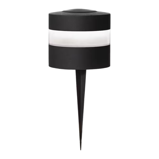
PACKAGE CONTENTS
A –Lamp body x 1
Per assembly and Installation
1
Detect PIR deck lights pairing
What to know before intall:
–Decide which PIR Deck Lights will be grouped (up to 10 fixtures).
–Open the plastic cover on back of each PIR Deck Light.
–Refer to the "Pairing via DIP Switch'' Step to pair the deck lights.
–Close the plastic cover (to prevent water go inside fixture).
–When the gear is adjusted to "ON", it is "1"
- If operating only one fixture, place the fixture in its permanent location.
- To operate multiple fixtures, please pair the fixtures before installation,
follow the PAIR steps below
Lift the plastic cover (1) by hand, and then slided the swith (2) to the
□
PIR.
There is a DIP switch on the top of fixture, there have 4 bottons on the
□
switch can be slided to up and down. The fixtures with the switch
bottons in the exactly same setting will be paired as a group . Groups
can be set freely (except "0000" and "1111").
When at PIR off mode (0000), fixture is at off status, will not pair.
□
When at PIR test mode (1111), fixture will turn on after detecting
□
motion whenever at day or night, then turn off after 3S of delay.
If pairing lost efficacy, slided the swith (2) to the OFF, and then slided
□
to PIR again.
B – Wire Connector(with 12 in. wire attached to lamp body)
2
Preliminary motion sensor and pairing test
General Notes:
–When the transformer is turned off the fixture light will turn
off, then PIR function become active and converts to battery
power.
–PIR Function is only active after the sensor detects the
environmental brightness at less than 50LUX at night.
–When the sensor detects the environmental brightness of less
than 50LUX, plus PIR detects motion, the deck light will turn on
and stay on for 1 minute before turning off.
–When the sensor detects the environmental brightness higher
than 200LUX, after a 90 second delay time, deck light will turn
off. The purpose of setting 90 second delay is to prevent the
200LUX brightness caused by a flash of lightning or car light.
- Test the motion sensor function of a single deck light.
Connect path light into main power cord by wire connectors.
□
Stir 4 buttons up to "ON" (Mode 1111) to make deck light on
□
test mode.
Cover the PIR sensor with light blocking object, to do
□
preliminary function test.
Remove the light blocking object, this path light will be
□
powered on, this means that the single path light pairing
function works.
- Test the pairing function of multiple deck lights.
Connect each path light into main power cord by wire
□
connectors (up to 10 deck lights).
Stir 4 buttons in any mode (except "0000" and "1111"), which
□
makes the path light enter the multi-lamp pairing test mode.
The mode of all path lights that need to be paired needs to be
□
set to the same.
Cover the PIR sensor with light blocking object to each path
□
lights to do preliminary function test.
Remove the light blocking object of one path light, this path
□
lights will be powered on. The rest of path lights in a group will
be sequentially powered on. This means function of motion
sensor and wirelessly link of path lights works.
1
Item # 1007 891 901
Model # KXX1501LX-01
Use and Care Guide
LED MOTION SENSOR
PATH LIGHTS
C –Ground Stake (6.53 in.) x1
Advertisement
Table of Contents

Related Manuals for HAMPTON BAY KXX1501LX-01


Summary of Contents for HAMPTON BAY KXX1501LX-01
- Page 1 Item # 1007 891 901 Model # KXX1501LX-01 Use and Care Guide LED MOTION SENSOR PACKAGE CONTENTS PATH LIGHTS A –Lamp body x 1 B – Wire Connector(with 12 in. wire attached to lamp body) C –Ground Stake (6.53 in.) x1...
-
Page 2: Assembly And Installation
Assembly and Installation Attaching and installing the light Connecting the wires WARNING: The wire connector (B) contacts have sharp edges for WARNING Never push the fixture into the ground by the lamp body (A) piercing the main low voltage cable. To avoid injury, do not touch or use a hammer to insert the ground stake (C) into the ground the metal contacts. -
Page 3: Technical Specifications
Technical Specifications Up t SPECIFICATIONS Up to 16.5 ft. (varies with surrounding temperature) Motion Sensor Range Sensor Detection Angle 90° Power supply AC 12V Installation Height Ideally, 1.31 ft. –0.65 ft. (0.4 – 0.2 m.) above the ground. Non-replaceable battery Rechargeable Li-ion Battery 3.7V, 800mA , 2.96 Wh Charging time 4 hours at charging current 300mA... -
Page 4: Troubleshooting
Troubleshooting Problem Possible Cause Solution □ □ Check the outlet and ensure that a breaker or GFCI circuit has not been tripped. The fixture will There is no power. □ □ Follow the wires from the fixture and ensure a continuous connected path back to the not light. - Page 5 Artículo # 1007 891 901 Modelo # KXX1501LX-01 GUÍA DE USO Y MANTENIMIENTO SENSOR DE MOVIMIENTO LED LUZ DE RUTA CONTENIDO DEL PAQUETE Conector de Cable ( con cable de 12pulgadas B – Estructura de la Lámpara A – fijado a la estructura de la lámpara) x1 E –Estaca de Tierra (6.53 pulgadas)
- Page 6 Montaje e Instalación (continuación) Fijando e instalación de lámparas Conectando los cables ADVERTENCIA Nunca empuje la lámpara al suelo a través del ADVERTENCIA: Los contactos del cable conector (B) tienen estructura de la lámpara (A) o utilice un martillo para insertar la bordes filosos para atravesar el cable principal de bajo voltaje.
-
Page 7: Especificaciones Técnicas
Especificaciones técnicas Up t ESPECIFICACIONES Hasta 16,5 pies (varía con la temperatura ambiente) Rango del sensor de movimiento Ángulo de detección del sensor 90° Fuente de alimentación AC 12V Altura de instalación Idealmente, de 0,4 a 0,2 m (1,31 pies a 0,65 pies) por encima del suelo. Batería no reemplazable Batería recargable de iones de litio de 3,7 V, 800 mA, 2,96 Wh Tiempo de carga... -
Page 8: Solución De Problemas
Solución de Problemas Problem Possible Cause Solution □ □ Verifique el tomacorriente y asegúrese que no esté apagado el interruptor o circuito GFCI. El accesorio no No hay corriente. □ □ Siga los cables desde el accesorio y asegúrese que esté en buen estado bien conectado al enciende. -
Page 9: Fcc Warning
FCC Warning Warning: Changes or modifications to this unit not expressly approved by the party responsible for compliance could void the user’s authority to operate the equipment. NOTE: This equipment has been tested and found to comply with the limits for a Class B digital device, pursuant to Part 15 of the FCC Rules.
Need help?
Do you have a question about the KXX1501LX-01 and is the answer not in the manual?
Questions and answers