Table of Contents
Advertisement
Quick Links
www.sigineer.com
Sigineer Power
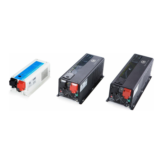
Pure Sine Wave Inverter/Charger
User's Manual(1.5KW to 6KW)
Version 6.0 (PN:50000-20221216)
Sigineer Power Limited
Email: info@sigineer.com
TEL: +86 769 82817616
WhatsApp / iMessage / Wechat :+86 189 9808 0464
US Warehouse: 205 E Alma Ave A6, San Jose, CA 95112
Add: Bld A, Jiali Industrial Zone, Yuanfen Rd, Longhua, Shenzhen, 518100, China
Manufacturer Information
1
Advertisement
Table of Contents

Related Manuals for Sigineer Power PSW71512NC


Summary of Contents for Sigineer Power PSW71512NC
- Page 1 Sigineer Power Pure Sine Wave Inverter/Charger User’s Manual(1.5KW to 6KW) Version 6.0 (PN:50000-20221216) Sigineer Power Limited Email: info@sigineer.com TEL: +86 769 82817616 WhatsApp / iMessage / Wechat :+86 189 9808 0464 US Warehouse: 205 E Alma Ave A6, San Jose, CA 95112...
-
Page 2: Table Of Contents
Appendix 3: Circuitry Scheme ..............................36 Please record the Sigineer Power unit’s model and serial number in case you need to provide this information in the future. It is much easier to record this information now than try to gather it after the unit has been installed. -
Page 3: Important Safety Information
All wires should be copper conductors. 1.1 General Safety Precautions 1.1.1 Before installing and using the Sigineer Power Pure Sine Wave Inverter/Charger, read the manual and cautionary markings on the Inverter/Charger enclosure. Be sure to read all instructions and cautionary markings for any equipment attached to this unit. -
Page 4: Introduction
The idle consumption of the Sigineer Power inverter/charger is ultra low, roughly 1.5% of its rated power. Loaded with full linear loads, the maximum THD of the Sigineer Power is 3% at nominal battery voltage and 10% at low battery voltage alarm point. -
Page 5: Application
Model # Nominal Power DC Input AC Input AC Output PSW71512NC 1500W 12Vdc 120Vac 120Vac PSW71524NC 1500W 24Vdc 120Vac 120Vac APC3012NC 3000W 12Vdc 120Vac 120Vac APC3012D 3000W 12Vdc 240Vac 120/240Vac APC3024NC... - Page 6 SIDE VIEW OF MODEL # : PSW71512NC / PSW71524NC SIDE VIEW OF MODEL # : APC3012NC /APC3024NC /APC3048NC/APC4012NC/APC4024NC/APC4048NC...
-
Page 7: Features
www.sigineer.com SIDE VIEW OF MODEL # : APC3012D /APC3024D/APC3048D/APC4012D/APC4024D/APC4048D/APC6024D/APC6048D 2.4 Features Auto Generator Start Battery Temperature Sensing for increased charging precision Lithium Battery(0Vdc) Wakeup Automatic Neutral to Ground Bonding for 120Vac models Maximum THD: 3% at nominal battery voltage Maximum 90% conversion efficiency Powerful 4-stage power factor corrected battery charger, settable from 0%-100% High surge output capability, 300% peak load for 20 seconds Fully isolated AC output from battery input... -
Page 8: Electrical Performance
2.5.2 AC Charger The Sigineer Power pure sine wave inverter/charger is equipped with an active PFC (Power Factor Corrected) multistage battery charger. The PFC feature is used to control the amount of power used to charge the batteries in order to obtain a power factor as close as possible to 1. - Page 9 48-54Hz for 50Hz (58-64Hz for 60Hz). The Sigineer Power pure sine wave inverter/charger has a very rapid charge current available, and the max charge current can be adjusted from 0%-100% via a liner switch on the DC side of the inverter. This will be helpful if this powerful charger apply charging on a small capacity battery bank.
- Page 10 The de-sulphation charging should not be carried out on batteries with good conditions. For Sigineer Power’s model of APC6024D and APC6048D Inverter chargers, the battery type selector position of “9” is customized with special charging algorithm for lithium battery modules from Tesla Model The algorithm has only Bulk Charging (Constant Current) to charge the battery, when the battery is charged to high voltage alarm, the charger will shut off and inverter goes to battery mode.
- Page 11 Warning: The output of these units will be de-rated by about 10% when the battery voltage drops below the nominal cut off of 20V and 40V. For other models, the battery type selector position of “9” is customized with special charging algorithm for Sigineer Power lithium battery packs Model # PSW71512NC...
-
Page 12: Transfer
2.5.4 Power Saver There are two different working statuses for SIGINEER POWER inverter: “Power On” and “Power Off”. When power switch is in “Unit Off” position, the inverter is powered off. When power switch is turned to either “Power Saver Auto” or “Power Saver Off”, the inverter is powered Power saver function is dedicated to conserve battery power when AC power is not or little required by the loads. -
Page 13: Protections
50W between Hot1 and Neutral and 200W between Hot 1 and Hot 2. There is no load detection between Hot2 and Neutral. The whole Sigineer Power inverter line is designed with extraordinarily low idle power consumption which is approximately 2.5% of its rated power. -
Page 14: Led Indicator
Fault (shutdown Output) after 30 seconds. After tempreture drops to 90º C(194℉), the switch has to be reset to activate the inverter. The Sigineer Power Inverter is with back feeding protection which avoids presenting an AC voltage on the AC input terminal in Invert mode. -
Page 15: Audible Alarm
www.sigineer.com Whichever first switches from “Unit Off” to “Power saver off” or “Power saver on”, it will power the inverter on. If the commands from the two panels conflict, the inverter will accept command according to the following priority: Power saver on> Power saver off> Power off Only when both panels are turned to “Unit Off”... -
Page 16: Fan Operation
2.5.9 FAN Operation For Sigineer Power 1500W-6000W models, there is one multiple controlled DC fan. The DC fan is designed to operate according to the following logic: Condition Enter Condition Leave condition Speed T ≤ 60℃(140℉) HEAT SINK T > 65℃(149℉) 65℃(149℉)≤... - Page 17 SW5: AC/Battery Priority The Sigineer Power inverter chargers are designed with AC/Battery priority switch (DIP switch #5). Switch the battery priority selector to Position “0” for AC priority mode, Position”1” for battery priority mode.
-
Page 18: Auto Generator Start
www.sigineer.com The AC/Battery Priority function can be activated by sliding the switch even when the inverter is in operation. Note: In battery priority mode, when qualified AC inputs for the first time and the battery voltage is below 12.5Vdc (12.5Vdc for 12Vdc, 25Vdc for 24Vdc, 51Vdc for 48Vdc), the inverter will first carry out a cycle of bulk charging and absorb charging, the inverter will not go into float charging mode. -
Page 19: Battery Temperature Sensing
For more detailed technical information, please contact us at info@sigineer.com . 2.5.13 GFCI Outlet For Sigineer Power 1500W to 6000W 120Vac single phase and 120/240Vac split phase models, there is a GFCI (ground-fault circuit interrupter) outlet in the vicinity of the AC terminal block. -
Page 20: Automatic Neutral-To-Ground Bonding
www.sigineer.com The GFCI is an electrical safety device that quickly breaks an electrical circuit with leakage current to ground. It is to protect equipment and to reduce the risk of serious harm from an ongoing electric shock. This GFCI is wired in parallel with the AC terminal block and they can output a maximum of nominal power. -
Page 21: Lithium Battery Wakeup
This makes it possible for a charger to charge ordinarily. The whole line of Sigineer Power inverters will use AC input power to wake up overdischarged lithium battery by a boost circuitry. When they detect a 0V battery, the charger will output a small current to awaken the lithium batteries. -
Page 22: Other Features
www.sigineer.com Once the lithium battery voltage is charged back to normal or over nomnal voltage, the charger will proceed with the preset charging settings. 2.5.16 Other Features Low Battery Voltage Recovery Start After low battery voltage shut off (10V for 12V model or 20V for 24V model or 40V for 48V model), the inverter is able to restore to work after the battery voltage recovers to 13.5V/27V/54V(with power switch still in “On”... - Page 23 www.sigineer.com 12 Vdc 90mm² 120mm² 48 Vdc 30mm² 45mm² 24 Vdc 45mm² 60mm² 24 Vdc 75mm² 95mm² 48 Vdc 25mm² 30mm² 48 Vdc 40mm² 50mm² 24 Vdc 90mm² 120mm² 48 Vdc 45mm² 60mm² Please follow the above minimum wire size requirement. One cable is always best, but if there is a problem obtaining for example 100mm²...
-
Page 24: Ac Wiring Recommendation
Send email to info@sigineer.com. Wiring Option 1 120V single phase Input: Hot line+Neutral+Ground Output: Hot line+Neutral+Ground For Model # PSW71512NC/PSW71524NC/APC 3012NC/APC3024NC/APC3048NC /APC4012NC/APC4024NC/APC40 48NC Wiring Option 2 120/240V split phase... - Page 25 www.sigineer.com Wiring Option 3 120/240V split phase Input: Hot line+ Hot line +Ground Output: Hot line +Neutral Remark: In this case, each output hotline can only carry a max of half the rated capacity. For Model # APC3012D/APC3024D/APC3048D/ APC4012D/APC4024D/APC4048D/ APC6024D/APC6048D Caution: Wiring Option 2 and Wiring Option 3 are only allowed for split phase models.
-
Page 26: Grounding
www.sigineer.com 3.4 Grounding Connect an AWG 8 gauge or greater copper wire between the grounding terminal on the inverter and the earth grounding system or the vehicle chassis. -
Page 27: Mounting Flange
3.5 Mounting Flange Model #: PSW71512NC PSW71524NC Model #: APC3012NC APC3024NC APC3048NC APC4024NC APC4048NC APC3012D/ APC3024D/ APC3048D/ APC4024D APC4048D... - Page 28 www.sigineer.com Model #: APC4012NC APC4012D/ APC6024D/ APC6048D Side View Model #: APC3012NC APC3024NC APC3048NC APC4012NC APC4024NC APC4048NC APC3012D/ APC3024D/ APC3048D/ APC4012D/ APC4024D APC4048D APC6024D/ APC6048D...
-
Page 29: Maintenance & Troubleshooting
4 Maintenance & Troubleshooting This troubleshooting guide contains information about how to troubleshoot possible error conditions while using the SIGINEER POWER Pure Sine Wave Inverter/Charger. The following chart is designed to help you quickly pinpoint the most common inverter failures. - Page 30 www.sigineer.com Symptom Possible Cause(s) Recommended Solution(s) Inverter will not turn on during Batteries are not connected, loose Check the batteries and cable initial power up. battery-side connections. connections. Check DC fuse and breaker. Low battery voltage. Charge the battery. No AC output voltage and no Inverter has been manually Press the switch to Power saver indicator lights ON.
-
Page 31: Warranty
We warrant this product against defects in materials and workmanship for a period of one year from the date of purchase and will repair or replace any defective Sigineer Power Inverter when directly returned, postage prepaid, to manufacturer. This warranty will be considered void if the unit has suffered any obvious physical... -
Page 32: Appendix 1 : Sigineer Power 1500W Inverter/Charger Spec Sheet
Appendix 1 : Sigineer Power 1500W Inverter/Charger Spec Sheet Electrical Specifications Model # PSW71512NC PSW71524NC Continuous Output Power 1500W 1500W Surge Rating(20s) 4500W 4500W Output Waveform Pure Sine wave/Same as input(Bypass mode) Nominal Efficiency 90%(Peak) Line Mode Efficiency >95% Power Factor 0.9-1.0... - Page 33 www.sigineer.com De-sulphation 15.5 for 4hrs Note For PSW71524NC, the value is 2 times of above figures. Input Voltage Waveform Sine wave (Grid or Generator) Nominal Voltage 120Vac/230Vac Low Voltage Trip 80Vac/154Vac± 4% Low Voltage re engage 90Vac/164Vac± 4% High Voltage Trip 140Vac/253Vac±...
-
Page 34: Appendix 2 : Sigineer Power 2000W-6000W Inverter/Charger Spec Sheet
Appendix 2 : Sigineer Power 2000W-6000W Inverter/Charger Spec Sheet Electrical Specifications Model Continuous Output Power 2000W 3000W 4000W 5000W 6000W Surge Rating(20s) 6000W 9000W 12000W 15000W 18000W Capable of Starting Electric Motor Output Waveform Pure Sine wave/Same as input(Bypass mode) - Page 35 www.sigineer.com Open Lead Acid 14.8/13.3 Calcium 15.1/13.6 De-sulphation 15.5 for 4hrs Remote Control Yes. Optional Input Voltage Waveform Sine wave (Grid or Generator) Nominal Voltage 120Vac 240Vac Low Voltage Trip 80V/90V± 4% 184V/154V± 4% Low Voltage re engage 90V/100V± 4% 194V/164V±...
-
Page 36: Appendix 3: Circuitry Scheme
www.sigineer.com Appendix 3: Circuitry Scheme Circuitry scheme for Inverter Mode Circuitry scheme for AC Mode... - Page 37 READ THIS MANUAL BEFORE INSTALLATION, IT CONTAINS IMPORTANT SAFETY, INSTALLATION AND OPERATING INSTRUCTIONS. KEEP IT IN A SAFE PLACE FOR FUTURE REFERENCE. Sigineer Power Limited Email: info@sigineer.com TEL: +86 769 82817616 WhatsApp / iMessage / Wechat :+86 189 9808 0464...
Need help?
Do you have a question about the PSW71512NC and is the answer not in the manual?
Questions and answers