Table of Contents
Advertisement
Product Variants
Model
SOM-352
V2X mPCIe System-On-Module, 0A1
SOM-352EC
V2X mPCIe System-On-Module, V2Xcast
SOM-352ED
V2X mPCIe System-On-Module, V2Xcast
SOM-352UC
V2X mPCIe System-On-Module, V2Xcast
SOM-352UD
V2X mPCIe System-On-Module, V2Xcast
Reviewers
Department
Name
PD
Nidor Huang
RD
P.C. Kang
Modification History
Revision
Date
0.1
2021/08/19
0.2
2021/10/13
0.3
2021/11/15
0.4
2022/04/15
0.5
2022/07/08
A printed version of this document is an uncontrolled copy
© 2023 Unex Technology Corporation – Company Confidential
Quick Start Guide
for
SOM-352 Family
Description
Acceptance Date
2023/05/10
2023/05/10
Originator
Nidor Huang
Creating document
Adding product variants
Adding limited warranty policies, safety guidelines
and product appearance
Nidor Huang
Adding reset and 1PPS guidelines
Adding software settings
Rearranging chapter order
Changing document type from HDG to QSG
Updating J1.1 description
Nidor Huang
Adding antenna cable extraction instructions
Adding troubleshooting
Nidor Huang
Adding GNSS antenna detection mechanism
Modifying antenna cable extraction instructions
Nidor Huang
Adding tamper backup power description
Doc. No: Unex-QSG-21-003
Document Number
Revision
Authors
®
- C-V2X stack, Europe, 0A1
- ITS-G5 stack, Europe, 0A1
®
®
- C-V2X stack, USA, 0A1
®
- WAVE stack, USA, 0A1
Note
Comment
Unex-QSG-21-003
0.9
Nidor Huang
1/30
Advertisement
Table of Contents

Related Manuals for Unex SOM-352 Series


Summary of Contents for Unex SOM-352 Series
- Page 1 2022/04/15 Nidor Huang Adding GNSS antenna detection mechanism Modifying antenna cable extraction instructions 2022/07/08 Nidor Huang Adding tamper backup power description 1/30 A printed version of this document is an uncontrolled copy © 2023 Unex Technology Corporation – Company Confidential...
- Page 2 Updating BOOTSTRP timing description Updating product photos Updating Unex logo 2023/03/08 Nidor Huang Adding GNSS reset in Unex BSP interface settings 2023/05/10 Nidor Huang Changing Ethernet over USB protocol to RNDIS 2/30 A printed version of this document is an uncontrolled copy...
-
Page 3: Table Of Contents
9.10.1.2. Standby Mode ................24 9.10.2. Test Mode ..................... 24 9.11. Thermal Management ..................25 9.12. Firmware Upgrade ....................25 9.12.1. Manual control ..................25 3/30 A printed version of this document is an uncontrolled copy © 2023 Unex Technology Corporation – Company Confidential... - Page 4 12.2. No Response After Applying Power ..............30 IST OF IGURES Figure 1: SOM-352 series appearance ..................8 Figure 2: Functional block diagram ................... 8 Figure 3: Antenna connectors ....................12 Figure 4: Antenna cable extraction tool ................... 13 Figure 5: V2X antennas EX-55/EX-53 ..................13 Figure 6: I/O Cable mating component P/N ................
- Page 5 Doc. No: Unex-QSG-21-003 5/30 A printed version of this document is an uncontrolled copy © 2023 Unex Technology Corporation – Company Confidential...
-
Page 6: Objective
Customer's sole and exclusive remedy and the entire liability of Unex under this limited warranty will be, at Unex's option, return for repair to Unex's repair center with freight and insurance prepaid or shipment of a replacement within the warranty period or a refund of the purchase price if the hardware is returned to Unex. -
Page 7: Safety Guidelines
Software products. • Products dismantled or opened by unauthorized persons. Please contact a • representative of Unex if you need advanced technical support. Products with an altered and/or damaged serial number. • Loss of data or software. •... -
Page 8: Functional Block Diagram
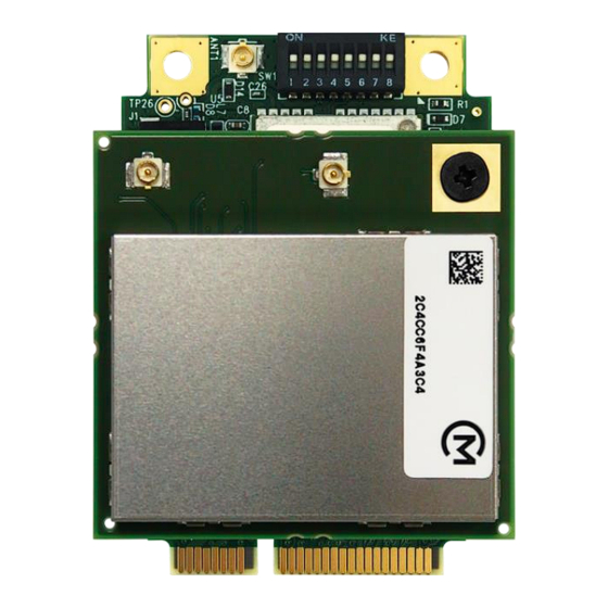
Doc. No: Unex-QSG-21-003 BOTTOM Figure 1: SOM-352 series appearance 6. Functional Block Diagram Figure 2: Functional block diagram 8/30 A printed version of this document is an uncontrolled copy © 2023 Unex Technology Corporation – Company Confidential... -
Page 9: Electrical Characteristics
TAMPER# kΩ RPD (Equivalent pull-down) TAMPER# VOL (Output low level voltage) IOL= 4mA VOH (Output high level voltage) IOH= 4mA 9/30 A printed version of this document is an uncontrolled copy © 2023 Unex Technology Corporation – Company Confidential... -
Page 10: Power Consumption
Power Source Voltage (V) Typical High 0.34 0.40 25°C 3.3 Vaux 0.100 0.105 0.110 0.38 0.44 85°C 3.3 Vaux 0.105 0.110 0.115 10/30 A printed version of this document is an uncontrolled copy © 2023 Unex Technology Corporation – Company Confidential... -
Page 11: I/O Interfaces
The SOM-352 mPCIe module is provided with three 50 Ω RF connectors (see IGURE 3: A NTENNA CONNECTORS two V2X antennas • 11/30 A printed version of this document is an uncontrolled copy © 2023 Unex Technology Corporation – Company Confidential... -
Page 12: Figure 3: Antenna Connectors
It is recommended to extract the cable using a proper extraction tool suggested by the cable plug manufacturer. For I-PEX plugs please use I-PEX 90192-001 or 90224- 001. 12/30 A printed version of this document is an uncontrolled copy © 2023 Unex Technology Corporation – Company Confidential... -
Page 13: Ghz V2X
The V2X antenna ports has a built-in antenna detection function (see 6). This ABLE detection mechanism only works with Unex V2X antennas EX-55 or EX-53 antennas. EX- 55/EX-53 antennas are not included in SOM-352 product package and can be purchased separately. -
Page 14: Gnss
1 - The antenna current is below the normal range (OPEN) • 2 - The antenna current is above the normal range (SHORT) • 14/30 A printed version of this document is an uncontrolled copy © 2023 Unex Technology Corporation – Company Confidential... -
Page 15: Mini Pcie Card Pinout
UART received data Proprietary UART_TX O (PU) UART transmitted data Proprietary Ground Not connected Not connected Ground Ground Not connected Not connected 15/30 A printed version of this document is an uncontrolled copy © 2023 Unex Technology Corporation – Company Confidential... -
Page 16: Table 9: Som-352 Mini Pcie Row 1 Pinout
BOOTSTRP I (PD) 1: Boot from USB0 (DFU mode) Proprietary BOOT_SW OFF: 0/1/NC: Boot from USB0 (DFU mode) Not connected Ground 16/30 A printed version of this document is an uncontrolled copy © 2023 Unex Technology Corporation – Company Confidential... -
Page 17: I/O Cable Pinout
Internally tied with mPCIe P51 J1.7 Ground The 7-pin cable connector is Molex Pico-Lock system 504051-0701 and the contact is 504052-0098. 17/30 A printed version of this document is an uncontrolled copy © 2023 Unex Technology Corporation – Company Confidential... -
Page 18: Dip Switch
In order to avoid interference and to keep 5V power from damaging your system board, it is important to set the DIP switch to correct positions before connecting the I/O cable. 18/30 A printed version of this document is an uncontrolled copy © 2023 Unex Technology Corporation – Company Confidential... -
Page 19: Design-In Guidelines
If the SOM-352 halts or resets while performing a V2X RF transmission, it is • recommended to add a bulk capacitor on the 5V trace near the mPCIe connector to 19/30 A printed version of this document is an uncontrolled copy © 2023 Unex Technology Corporation – Company Confidential... -
Page 20: Power Sequence
Minimize trace lengths, number of vias, and capacitive loading. The layout guidelines for the USB data lines (mPCIe pin 36, 38) is listed below. And a 20/30 A printed version of this document is an uncontrolled copy © 2023 Unex Technology Corporation – Company Confidential... -
Page 21: Serial Port
(e.g., 5V to 3.3V or 1.8V to 3.3V). The only configuration that does not need level translation is the 3.3V UART. 21/30 A printed version of this document is an uncontrolled copy © 2023 Unex Technology Corporation – Company Confidential... -
Page 22: Reset
0 > /sys/class/gpio/gpio100/value # 0=Ext_GNSS, 1=Int_GNSS To let the above setting take effect upon next boot-up, please append the above lines /home/root/ext-fs/usr/bin/at_startup 22/30 A printed version of this document is an uncontrolled copy © 2023 Unex Technology Corporation – Company Confidential... -
Page 23: Bootstrp
API that allows enabling the tamper detection mechanism. Calling this API will move tamper HW state from the testing mode to the production mode. Once called, it 23/30 A printed version of this document is an uncontrolled copy © 2023 Unex Technology Corporation – Company Confidential... -
Page 24: Production Mode
Each invocation of the tamper signal increments an internal counter within the eHSM. This counter can then be inquired by calling the eHSM runtime status API, 24/30 A printed version of this document is an uncontrolled copy © 2023 Unex Technology Corporation – Company Confidential... -
Page 25: Thermal Management
UNCTIONS BOOT_SW ON: Normal boot (boot from NAND) • BOOT_SW OFF: Firmware upgrade (boot from USB0, DFU mode) • 25/30 A printed version of this document is an uncontrolled copy © 2023 Unex Technology Corporation – Company Confidential... -
Page 26: Host Gpio Control
SOM-352 to the system board PCB. User can choose TE 2041119-1 as a candidate for such a mini PCIe connector. 26/30 A printed version of this document is an uncontrolled copy © 2023 Unex Technology Corporation – Company Confidential... -
Page 27: Component Keep Out Area
SOM-352, the system board side component height should be carefully considered according to the datasheet of mPCIe connector selected. 27/30 A printed version of this document is an uncontrolled copy © 2023 Unex Technology Corporation – Company Confidential... -
Page 28: Software Settings
Doc. No: Unex-QSG-21-003 11. Software Settings The following BSP settings are applicable for Unex software package only. Table 13: Unex BSP interface settings Function Description Console UART3, 115200bps, 8N1, ttyAMA2 GNSS NMEA UART1, 230400bps, 8N1, ttyAMA1 GNSS Debug (Opt.) UART2, 230400bps, 8N1, ttyAMA0 GPIO111, 0->1 = GNSS module reset (cold start, clear SRAM... -
Page 29: Linux
RNDIS driver are not included here because it may vary from one distribution to another. user@host:~$ lsmod | grep rndis Check if the Unex device has been registered as a RNDIS device with a network interface. user@host:~$ dmesg | grep -i -C4 unex Ping the RNDIS device IP of SOM-352 and check if it is alive. -
Page 30: Troubleshooting
Change the SOM-300 family RNDIS IP address setting. Please refer to the IP A section in Unex’s documentation, which can HANGING YSTEM DDRESS be found in Unex’s software release package. 30/30 A printed version of this document is an uncontrolled copy © 2023 Unex Technology Corporation – Company Confidential...
Need help?
Do you have a question about the SOM-352 Series and is the answer not in the manual?
Questions and answers