
Subscribe to Our Youtube Channel
Related Manuals for CASE CONSTRUCTION 450DX


Summary of Contents for CASE CONSTRUCTION 450DX
- Page 1 450DX Vibratory Mini Tandem Compactor OPERATOR’S MANUAL Part number 51635014 edition English May 2019 Replaces part number 51435024...
-
Page 2: Table Of Contents
Contents 1 GENERAL INFORMATION Foreword ................. . . 1-1 Intended use. - Page 3 Shipping transport Transporting on a trailer ..............5-1 Recovery transport Towing the machine .
-
Page 5: General Information
For any clarification or further information, please contact our regional offices or our authorised representative. NOTE: In any circumstances no part or the whole of this manual can be copied or reprinted without the written per- mission of CASE CONSTRUCTION Equipment (India) private limited. -
Page 6: Intended Use
All persons who will be operating this machine shall possess a valid local vehicle operating permit and/or other appli- cable local age work permits. Consult an authorized dealer or CASE CONSTRUCTION Equipment (India) Pvt. Ltd. on changes, additions, or modifications that can be required for this machine to comply with various country regulations and safety requirements. -
Page 7: Note To The Owner
• Learns and practices safe use of machine controls in a safe, clear area before operating this machine on a job site. It is your responsibility to observe pertinent laws and regulations and follow CASE CONSTRUCTION Equipment India Pvt. Ltd. instructions on machine operation and maintenance. - Page 8 Warranty service Our representatives ( CASE CONSTRUCTION India Service Personnel) are at your disposal to assist you in maintaining your machine in perfect working condition. Our personnel will carry out four machine service during the warranty period.
-
Page 9: Product Identification
1 - GENERAL INFORMATION Product identification Record the machine and part identification numbers, if needed, give these numbers to your Dealer when you need parts or information for your machine. Keep a record of these numbers and your manufacturer’s statement or origin in a safe place. -
Page 10: Right, Left, Front, And Rear Of The Machine
1 - GENERAL INFORMATION Right, left, front, and rear of the machine PTIL14COM0013FC Top view Side view Rear view Front view... -
Page 11: Safety Information
2 - SAFETY INFORMATION 2 - SAFETY INFORMATION###_2_### Note to the owner This manual contains important information about the safe operation, adjustment, and maintenance of your soil com- pactor. This manual is divided into chapters as outlined in the table of contents. Refer to the index at the end of this manual for locating specific items about your machine. -
Page 12: Personal Safety
2 - SAFETY INFORMATION Personal safety This is the safety alert symbol. It is used to alert you to potential personal injury hazards. Obey all safety messages that follow this symbol to avoid possible death or injury. Throughout this manual and on Machine decals, you will find the signal words DANGER, WARNING, and CAUTION followed by special instructions. -
Page 13: Safety Rules
2 - SAFETY INFORMATION Safety rules Understand that your safety and the safety of other workers or nearby people is measured by how you service and operate this machine. Know the position and operation or all controls before you try to operate. Check all controls in a safe area before starting your work. - Page 14 2 - SAFETY INFORMATION • Always make sure the working area is clear of other persons, domestic animals, tools, etc. • Before starting the engine, be sure all operating controls are in the neutral or park lock position. • Start the engine only from the operator’s seat. Operate controls only when seated in the operator’s seat. •...
- Page 15 2 - SAFETY INFORMATION Safety rules - electrical storm safety • Do no operate machine during an electrical storm. • Do not make contact with the ground or objects outside the machine. • If you are on the ground during an electrical storm, stay away from machinery and equipment. Seek shelter in a permanent, protected structure.
- Page 16 2 - SAFETY INFORMATION • Travel speed should be such that complete control and machines stability is maintained at all times. Safety rules - safety decals The decals are intended for the personal safety of you and those working with you. Please take this manual, walk around your machine and note the content and location of the decals.
-
Page 17: Controls And Instruments
3 - CONTROLS AND INSTRUMENTS 3 - CONTROLS AND INSTRUMENTS###_3_### Access to operator's platform Warnings and preliminary checking • The machine must be used by authorized personnel only. • Make different idle operations assisted by specialized staff. • All control levers must be handled delicately and gradually. •... -
Page 18: Access To Operator's Platform
3 - CONTROLS AND INSTRUMENTS Access to operator's platform Machine access Face the machine when mounting and dismounting. Do not use the steering wheel or other controls or accessories as hand holds when entering or exiting the cab or operator’s platform. -
Page 19: Forward Controls
3 - CONTROLS AND INSTRUMENTS Forward controls Forward controls Accelerator lever The throttle lever is placed on right hand side of the op- erator beside the FNR lever allows the change of engine RPM by controlling the FIP (Fuel Injection Pump) Lever. The range of Lever is 900 –... - Page 20 3 - CONTROLS AND INSTRUMENTS Front drum frequency selector switch To operate the machine in front drum high or low fre- quency mode, select the desired mode by rotating the switch. PTIL15COM0062AB Front work lamps Press the emblem end of the rocker switch to acti- vate the front work lamps (1).
-
Page 21: Operator Control Panel
3 - CONTROLS AND INSTRUMENTS Operator control panel PTIL15COM0076HB... - Page 22 3 - CONTROLS AND INSTRUMENTS HOUR METER TEST SWITCH WATER TEMPERATURE GAUGE HORN PUSH BUTTON ENGINE OIL PRESSURE GAUGE IGNITION SWITCH NEUTRAL INDICATOR PARKING BRAKE SWITCH BATTERY NON -CHARGING INDICATOR PARKING LAMP SWITCH PARKING BRAKE INDICATOR HEAD LAMP HIGH & LOW BEAM SWITCH HIGH COOLANT TEMPERATURE REAR LAMP SWITCH...
- Page 23 3 - CONTROLS AND INSTRUMENTS 3. Engine Oil Pressure Gauge Engine oil pressure gauge indicates the engine lubrica- tion oil pressure . When the engine is operating at rec- ommended temperature the lubrications pressure value should be Low idle (Bar) High Idle (Bar) Min.
- Page 24 3 - CONTROLS AND INSTRUMENTS 6. Parking Brake Indicator Parking brake indicator glows when parking brake is en- gaged. Parking brake disengages when the travel con- troller (FNR) is forward / reverse position. If the parking brake is not disengaging, this indicator comes ON. Shut off the engine immediately, locate the cause and set right the problem.
- Page 25 3 - CONTROLS AND INSTRUMENTS 9. Hydraulic Filter Clog Indicator This indicator comes ON when the hydraulic oil filter clogs. Stop the machine operation and replace the filter element. Running the machine after filter clogging will contaminate the hydraulic circuit and can cause extensive damage to the hydraulic system.
- Page 26 3 - CONTROLS AND INSTRUMENTS 12. Voltmeter This show the voltage difference between the two battery terminals it is used to check the battery conditions ideally it should be between 11 to14 volts , else battery needs to be checked. PTIL15COM0078AB 13.
- Page 27 3 - CONTROLS AND INSTRUMENTS 15. Ignition Switch The ignition switch on the machine can be operated only with the key provided with the machine. To disconnect the battery to the ignition circuit, insert the key, turn anti- clockwise by 90°. PTIL15COM0054AB 16.
- Page 28 3 - CONTROLS AND INSTRUMENTS 18. Head Lamp High & Low Beam Switch To get the parking lamp switch ON, turn the parking lamp switch. PTIL15COM0057AB 19. Rear Lamp Switch To "ON" the rear work lamp, rotate the rear work lamp switch PTIL15COM0058AB 20.
- Page 29 3 - CONTROLS AND INSTRUMENTS 21. Water Pump Switch To switch "ON" water pump, rotate the water pump switch. PTIL15COM0060AB Both Drum High Or Low Frequency Switch To operate the machine in both drum high or low fre- quency mode, select the desired mode by rotating the switch.
- Page 30 3 - CONTROLS AND INSTRUMENTS 24. MCB To start the engine & ignition first switch ON the MCB. MCB will trip if any electrical fault occurs in machine. PTIL15COM0063AB 25. Hazard Switch Hazard push button is placed at left hand of the control tower.
-
Page 31: Operating Instructions
4 - OPERATING INSTRUCTIONS 4 - OPERATING INSTRUCTIONS###_4_### Commissioning the unit Commissioning operation The following pre-operation checks has to be carried out every day before starting the engine. • Check the fuel level in the fuel tank and top up if required. ○... - Page 32 4 - OPERATING INSTRUCTIONS PTIL15COM0077GA Now push the test switch (11) once to check all the indicators viz Hydraulic filter choke indicator (15) , Parking Brake Indicator (19) , Low Lube oil pressure Indicator (16), and High Coolant Temperature Indicator (20). Now turn the Ignition Key (10) further to crank start the engine.
-
Page 33: Assisted Starting (Jump-Starting)
4 - OPERATING INSTRUCTIONS Assisted starting (Jump-starting) Never try to start the machine when the batteries are de- fective or frozen. You can perform assisted starting or jump starting from other battery or machine. Only connect batteries (battery assemblies) with the same voltage. -
Page 34: Miscellaneous
4 - OPERATING INSTRUCTIONS Miscellaneous Cold temperature operation Cold weather conditions cause special problems. During the reconditions, your machine will require special attention to prevent serious damage. Cold weather maintenance will extend the service life of your machine. To start and operate your machine during cold ambient temperature, observe the following suggestion / instructions. Battery and electrical components: •... - Page 35 4 - OPERATING INSTRUCTIONS To prevent damage to the machine: • Keep the coolant at the correct level in the coolant reservoir and in the radiator. • See your dealer and have the de-aeration cap tested before hot weather starts. Replace the cap as required. •...
-
Page 36: Stopping The Unit
4 - OPERATING INSTRUCTIONS Stopping the unit Stopping the unit Shutting OFF the engine • Before you leave the machine, make sure the machine is parked on a level surface. The machine must be on level ground. • Set the vibration selector switch (7 or 8) to zero position. Exciter operation. •... - Page 37 4 - OPERATING INSTRUCTIONS ○ Ensure the operator’s seat is in normal position. ○ Ensure that articulation joint arrestor is disengaged. ○ Ensure that parking brake is not engaged (parking brake should be in off position). ○ Start up the engine. ○...
- Page 38 4 - OPERATING INSTRUCTIONS...
-
Page 39: Transport Operations
5 - TRANSPORT OPERATIONS 5 - TRANSPORT OPERATIONS###_5_### Preparing for road transport Transport dimensions PTIL15COM0201FA d1=d2 2123 1350 2680 1740 2990 1250 Shipping transport Transporting on a trailer WARNING Transport hazard! The machine can slip or fall from a ramp or trailer. Make sure the ramp and trailer are not slippery. Remove all oil, grease, ice, etc. -
Page 40: Recovery Transport
5 - TRANSPORT OPERATIONS 1. Locking level A. Operating position B. Locking position 2. Front roller frame 3. Rear roller frame You must know the rules or laws for safety that are used in each area that you will be in. Make sure that the truck and trailer are equipped with the correct safety equipment. - Page 41 5 - TRANSPORT OPERATIONS Towing Use the lugs at the front and rear roller frame for towing. Fix the articulation joint arrester. Interconnect “A” and “B” port of travel pump by unscrewing the main relief valve for free flow to the both hydraulic motor. Releasing parking brake In order to release the parking brake.
- Page 42 5 - TRANSPORT OPERATIONS Remove the wheel chocks Release the parking brake. If the parking brake does not disengage, disable the parking brake manually. No riders allowed. Make sure all other workers are out of the area.
-
Page 43: Working Operations
6 - WORKING OPERATIONS 6 - WORKING OPERATIONS###_6_### General information Operating the machine during running-in period WARNING Avoid injury and/or machine damage! During the run-in period for new machines or after overhaul, be aware that brakes may be less efficient and longer stopping distances may be required. -
Page 44: Operating The Machine At High Altitudes
6 - WORKING OPERATIONS Operating the machine at high altitudes NOTICE: Engine power is affected by the environment in which the machine is operated. The machine may be used up to a maximum altitude of 3500 m (11483 ft). As altitude increases, the atmospheric pressure and specific gravity of intake air decrease, which in turn reduces engine performance. -
Page 45: Operating The Machine At High Temperatures And Humidity
6 - WORKING OPERATIONS Operating the machine at high temperatures and humidity The higher the air temperature and humidity, the lower the engine performance. Both factors reducing performance are dependent on each other: • With every 10 °C (50 °F) of temperature increase, power drops by up to 4% (at constant 30% relative humidity) •... -
Page 46: Operating The Machine At Low Temperatures
6 - WORKING OPERATIONS Operating the machine at low temperatures NOTICE: Normal engine coolant operating temperature is 75 – 100 °C (167 – 212 °F). NOTICE: The machine may only be used at its full capacity after fluid has been heated to it’s minimum operating temperature. -
Page 47: Operating The Machine In Extremely Dusty Environment
6 - WORKING OPERATIONS Operating the machine in extremely dusty environment The after-cooler and radiator cleaning intervals. When working in an extremely dusty environment, shorten the intervals between: • Cleaning the after cooler. • Cleaning the radiator grill. NOTE: The air filter element has to be cleaned only when the clog indicator comes ON. NOTE: The recommended cleaning interval is a minimum of once a week or 50 h. -
Page 48: Operating With Vibration On Compacted And Hard Materials
6 - WORKING OPERATIONS Operating with vibration on compacted and hard materials WARNING Avoid injury and/or machine damage! Prolonged operation in this mode is prohibited, as it could negatively impact operator health or cause machine damage. Failure to comply could result in death or serious injury. W1070B When operating the machine with vibration on hard materials (e.g. -
Page 49: Working Operations
6 - WORKING OPERATIONS WORKING OPERATIONS Vibration WARNING Hazard to bystanders! Always sound the horn before starting the machine. Make sure the work area is clear of other persons, domestic animals, tools, etc. before you operate the machine. Never allow anyone in the work area during machine operation. - Page 50 6 - WORKING OPERATIONS...
-
Page 51: Maintenance
MAINTENANCE###_7_### General information Consumables For the very best protection of your investment, use the CASE CONSTRUCTION recommended lubrication and ser- vice products. Contact your dealer for these products and for any questions related to the machine’s service and lubrication requirements. -
Page 52: Maintenance
7 - MAINTENANCE Maintenance 1.General Remove any residues of material immediately after work- ing on soil. Check the machine visually for contamination and clean, if necessary. Retighten the screws and bolts, if necessary. If the ma- chine is in standstill for a long period, check all functions at regular intervals. - Page 53 7 - MAINTENANCE 3.AIR CLEANER NOTICE: The vent plug has holes to release the gases that are formed during the working cycle. Care should be taken to ensure that the vent holes are clean and not blocked with dust and dirt. For cleaning the air cleaner, Loosen the mounting band of the dust cup, remove the wing nut of the element and take out the element for checking &...
- Page 54 7 - MAINTENANCE 4 HYDRAULIC OIL FILTER The hydraulic oil filter is a fine mesh medium pressure filter. This is suction filter equipped with differential pres- sure indicator which shows indication of clogging of filter on control panel. filter is provided with a magnetic core which attracts all the ferrous particles formed by friction and wear forces.
- Page 55 7 - MAINTENANCE 5 MOUNTING RUBBER PAD Check rubber pads for cracks and distortion. Measure crack depth with a straightedge. If depth of crack exceeds 5 mm, replace rubber pads. 6 HYDRAULIC TANK For checking hydraulic oil level in the hydraulic tank, park the machine on the level ground.
- Page 56 7 - MAINTENANCE 8 WATER SPRINKLING SYSTEM : WATER SPRINKLING SYSTEM Cleaning the sprinkling tubes : Remove plugs of sprinkling tubes. Remove the sedi- ments, flush the tubes and refit the plugs. Cleaning of water filters : Remove the water filters located below the operator's plat- form Thoroughly clean and refit the water filters.
- Page 57 7 - MAINTENANCE 11 ELECTRICAL SYSTEM Check all the electrical lines, fuses and connections (ter- minals, plug connectors etc Check lighting system, which consists of: 1. Head lamps 2. Front indicators 3. Rear indicators Check the electric circuit of exciter and sprinkling system Check indicating lamps and instruments for functions.
-
Page 58: Maintenance Planning
7 - MAINTENANCE Maintenance planning Maintenance chart Maintenance work Maintenance instants After first In case 50 h Daily Regularly every of need or 15 days 200 h 500 h 1000 h 100 h or 1 or 2 or 4 or 6 month months months... - Page 59 7 - MAINTENANCE Maintenance work Maintenance instants After first 50 h case Daily Regularly every or 15 days need 500 h 100 h or 1 250 h or 1000 h or 6 or 4 month 2 months months months Oil Level in hydraulic tank (top up if required) Greasing at steering cylinder rod and head end...
- Page 60 7 - MAINTENANCE 7-10...
-
Page 61: Specifications
8 - SPECIFICATIONS SPECIFICATIONS###_9_### Technical feature of the machine Technical features of the machine Machine The front frame of this vibratory compactor is connected to the rear frame by means of an articulation joint. The front roller frame is a welded construction and mounted with ant vibration pads at the drum. The rear frame is also a welded construction with a box shaped hollow space at the rear end serving as fuel tank and water tank. - Page 62 8 - SPECIFICATIONS Brakes The hydrostatic system constitutes the service brake thus a separate service brake is not required. The spring loaded multiple disc brakes in the front travel motor serves as a parking brake. Similar brake system is in between in rear axle.
-
Page 63: General Specifications
8 - SPECIFICATIONS General Specifications Vibration Stage 1 (Low frequency) Vibration Stage 2 (High frequency) Exciter force per drum 27.36 KN 38.89 KN Exciter force per unit length 22 Kg/cm 31 Kg/cm Exciter frequency 55 Hz 65 Hz Nominal amplitude 0.6 mm Oscillating angle of front drum 10 degrees... -
Page 64: Engine Coolant Specifications
8 - SPECIFICATIONS Engine coolant specifications Make MAHINDRA & MAHINDRA [FES] LTD Type 4 stroke, 4 cylinder, direct injection water cooled engine Model MDI-2500 Bore 88.9 mm Stroke 101.6 mm Displacement 2523 CC Nature of aspiration Naturally aspirated Power rating 32.80 KW @ 2300 RPM, Direction of rotation Anti-clockwise when viewed from flywheel... -
Page 65: Propulsion
8 - SPECIFICATIONS Propulsion Type Hydrostatic system acting on both the drum. Travel pump Axial piston pump with manual displacement control. High speed - low torque, radial piston motor without brake on front drum Travel Motor and with brake on rear drum. 0 –... -
Page 66: Exciter Drive
8 - SPECIFICATIONS Exciter drive Type Hydrostatic system acting on the front and rear exciter shafts. Single shaft circular exciter. Kind of exciter Vibration pump Fixed displacement gear pump Fixed displacement gear motor Vibration motor... -
Page 67: Exciter Control
8 - SPECIFICATIONS Exciter control Stage 1 ( 55 Hz) Low frequency Stage 2 ( 65 Hz) High frequency... -
Page 68: Steering System
8 - SPECIFICATIONS Steering system Hydrostatic system acting via the steering wheel, steering unit and Type steering cylinder mounted in the articulated joint Steering pump Gear type Steering lock angle (L/H and R/H) 30 degrees Turning radius, inner inside/outside-3.6 / 4.8 m... -
Page 69: Electrical Systems
8 - SPECIFICATIONS Electrical systems Battery 12 V, 100 A·h Alternator 12 V, 35 A... -
Page 70: Hydraulic Oil Filter
8 - SPECIFICATIONS Hydraulic oil filter Type Inorganic multi-layer micro-fiber web Filter rating 12 Micron absolute Number of filters 8-10... -
Page 71: Brakes
8 - SPECIFICATIONS Brakes Hydrostatic Service brake Parking brake Spring applied hydraulically released. 8-11... -
Page 72: Sprinkling
8 - SPECIFICATIONS Sprinkling Type Pressurized water sprinkling system Water pump for the Electric drive (12 V) sprinkling device 8-12... -
Page 73: Service Refill Capacities
8 - SPECIFICATIONS Service refill capacities Travel circuit 350.0 bar (5075.0 psi) max. Vibration circuit 210.0 bar (3045.0 psi) max. Steering circuit 100.0 bar (1450.0 psi) max. 8-13... -
Page 74: Capacities
8 - SPECIFICATIONS Capacities Fuel tank 42 Liters Hydraulic oil tank 42 Liters Engine oil 7 Liters Water tank - Front + Rear 60 + 60 = 120 Liters Roller oil 1+1Litres Engine coolant system capacity 7 Liters 8-14... -
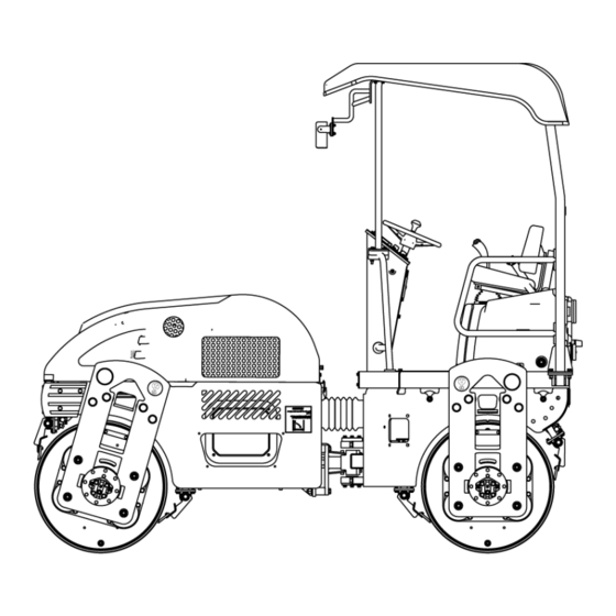
Page 75: Main Components Of The Machine
8 - SPECIFICATIONS Main components of the machine PTIL15COM0003GC Front Roller Assembly Radiator Oil Cooler Assembly Rear Roller Assembly Air Pre cleaner Front Chassis Frame Air cleaner Engine Lube Oil Filter Rear Chassis Operators Platform Forward Neutral Reverse (FNR) Lever Articulation Joint Throttle Lever Water Hydraulic Oil Tank... - Page 76 8 - SPECIFICATIONS Sprinkler Assembly Rear Tank Cover Canopy Roof Operator's Seat Assembly Engine Steering Wheel 1. Front Roller Assembly The front roller assembly is Coupled to the front chassis with the help of left & right supporting bracket. PTIL15COM0204AA 2.
- Page 77 8 - SPECIFICATIONS 4. Rear Chassis The rear chassis supports the rear roller assembly, Water Diesel tank, Operator's Platform & Canopy. This is con- nected to the Front chassis by means of an articulation joint. PTIL15COM0207AA 5. Operators Platform Operator's Platform is mounted on the rear chassis by means of AVM to cut down the vibrations, thereby enhanc- ing the Operator's comfort.
- Page 78 8 - SPECIFICATIONS 7. Water Hydraulic Tank The water-oil tank is mounted on the front chassis. It is divided in to two compartments- One acting as a water unit of capacity 60 liters and the other acting as a hydraulic oil unit of capacity 42 liters.
- Page 79 8 - SPECIFICATIONS 10. Travel Support -Front/Rear Travel Support, directly mounted on the travel motor, con- nects the roller assembly to the chassis on the travel side of the machine. PTIL15COM0213AA 11. Vibration Support-Front/Rear Vibration support directly mounted on the vibration sup- port plate by means of AVM, connects the roller assembly to the chassis on the vibration side of the machine.
- Page 80 8 - SPECIFICATIONS 13. Engine Hood The Engine compartment is covered with an engine hood for easy maintenance of engine compartment. The Hood is insu- lated from inside. PTIL15COM0016AB 14. Front Head Light Cover An aesthetically improved front headlight cover is mounted on the front chassis and supports the front working lights.
- Page 81 8 - SPECIFICATIONS 16. Canopy Roof A stylish, light weight canopy roof is mounted over the canopy support just above the operators seat. It protects the operator from the scorching rays of the sun and rain. PTIL15COM0019AC 17. Engine A Water cooled, Naturally aspirated diesel engine is mounted on the front chassis in the transverse direction.
- Page 82 8 - SPECIFICATIONS 19. Air Pre Cleaner Air pre cleaner is mounted on the radiator side of the en- gine. Its primary objective is to segregate dust particles from the incoming air flow. PTIL15COM0022AB 20. Air Cleaner A single element, wet type, heavy duty air filter is provided along with the engine.
- Page 83 8 - SPECIFICATIONS 22. Forward Neutral Reverse (FNR) Lever An ergonomically design FNR lever ensures a smooth transition during forward and reverse travel. PTIL15COM0025AB 23. Throttle Lever The throttle lever just placed beside the FNR lever allows the change of engine RPM by controlling the FIP (Fuel Injection Pump) Lever.
- Page 84 8 - SPECIFICATIONS 25. Travel Pump This is a infinitely variable displacement axial piston type pump. PTIL15COM0028AB 26. Vibration Block Two stages of vibration are obtained in the machine which is controlled by means of solenoid actuation in the vibra- tion block.
- Page 85 8 - SPECIFICATIONS 28. Rear Travel Motor This is a Radial piston, Low Speed, High Torque motor with parking brakes. PTIL15COM0031AB 29. Vibration Motor (Front & Rear) This a fixed displacement type gear motor. PTIL15COM0032AB 30. Return Suction Filter For trouble free operation the servo circuit incorporates a fine mesh pressure filter with 12 micron absolute rating equipped with sensor, which indicates the clogging of the filter in the control panel.
- Page 86 8 - SPECIFICATIONS 31. Scrapper Assembly To remove the asphalt and other particles from the surface of the drums two scrapers are mounted on the front drum and the rear drum each: To remove the asphalt and other particles from the surface of the drums two scrapers are mounted on the front drum and the rear drum each.
- Page 87 8 - SPECIFICATIONS 34. Steering Wheel Steering wheel, mounted on the steering column is er- gonomically placed for proper steering of the machine. PTIL15COM0037AB 8-27...
-
Page 88: Uses In Practice
8 - SPECIFICATIONS Uses in practice Uses in practice: Construction of roads, air fields, sports ground, dams and similar projects Compacting works Compaction of • Bituminous top • Binder • Base and Earthy base courses • Surface finishing • Stabilizing and mortaring work 8-28... -
Page 89: Identification Plates
8 - SPECIFICATIONS Identification plates A name plate is fixed at the location 1 which indicates the following details: • Machine serial number • Machine model name/number • Engine serial number/power • Total operating weight of the machine • Year of the manufacture Some of the major components of the machine have their own identification plates/stickers such as: •... -
Page 90: Torque Specifications
8 - SPECIFICATIONS Torque specifications Size Grade 8.8 Grade 10.9 Grade 12.9 5.5 N·m (4 lb ft) 7.5 N·m (5.5 lb ft) 9 N·m (6.6 lb ft) 9 N·m (6.6 lb ft) 12.5 N·m (9.2 lb ft) 15 N·m (11 lb ft) 22.5 N·m (16.5 lb ft) 31.5 N·m (23 lb ft) 36 N·m (26.5 lb ft) -
Page 91: Tool List
8 - SPECIFICATIONS Tool list Tool list Description Qty. Sl No. Part No. BU0620051 METAL TOOL BOX BU4630001 NAVTAL LOCK V204029/80031 SOCKET 30 A/F BU4580003 GREASE FITTING. M10(90 DEG)[BU0330 BU0620002 KEY POUCH. P20044405W DE SPANNER 6X 7 BU0510015 D/E SPANNER 10 * 11MM BU0510016 D/E SPANNER 12*13 - 126 BU0510025... - Page 92 8 - SPECIFICATIONS 8-32...
- Page 93 Index ###_Index_### Access to operator's platform........Assisted starting (Jump-starting) .
- Page 94 Right, left, front, and rear of the machine ....... Safety rules ......... . . Service refill capacities .
- Page 96 ORIFINAL INSTRUCTIONS - according to Directive 2006/42/EC, Annex I I.7.4.I OPERATOR’S MANUAL Dealer’s stamp TT4.80 TT4.90 CNH Industrial America LLC. reserves the right to make improvements in design and changes in specification at any time without notice and without incurring any obligation to install them on units previously sold. Specifications, descriptions, and illustrative material herein are as accurate as known at time of puplication, but are subject to change without notice.
Need help?
Do you have a question about the 450DX and is the answer not in the manual?
Questions and answers