Table of Contents
Advertisement
Advertisement
Table of Contents

Related Manuals for Oreck Air 16


Summary of Contents for Oreck Air 16
- Page 1 The Oreck Manufacturing Company Air 16 06/21/2011 Compiled by Clark DeNoble...
-
Page 2: Table Of Contents
Table of Contents Circuit Diagram Page 3-6 Tune-Up Page 7 Disassembly Page 8-13 General Instructions Page 8 Prefilter Page 9 Collector Cell Page 9 PCO Module Page 10 Fan Assembly Page 10 Control Section Page 11 Power Section Page 11 Back Cover Page 11 Control Section Components... -
Page 7: Tune-Up
Tune-Up Plug in the unit Press the Power button: The fan should start up fast then slow to Silence and the On and Silence indicators should light up. Press the Power button for Medium and High Power & Motor function: The speed should increase and the Speed Control applicable indicator should light up. -
Page 8: Disassembly
Control Section Inside Top Remote Control Sensor Window All Safety Interlock Switches are circled except the PCO Module Sense Switch. The Cell Sense Switch is not a safety switch. Module Exhaust Intake Cell Power Section Inside Base Disassembly Remember to start with a clean bench and a tray to put the screws in. Be sure the unit is NOT plugged in while servicing except to test functions. -
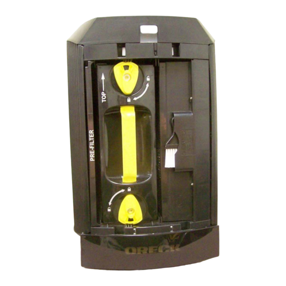
Page 9: Prefilter
Filtration Compartment 1. Remove the Prefilter Front Back 2. Unlock and remove the Collector Cell Assembly 3. Lift up the Precharge Assembly and remove from Collector Cell Precharge Assembly Collector Cell... -
Page 10: Fan Assembly
3. Remove the two screws indicated and pull out PCO Module. 1. To access the Fan Assembly for removal, the Exhaust Grill must be removed. In order to remove the Exhaust Grill the Control and Power Sections must be removed. -
Page 11: Pco Module
2. Control Section removal 4 screws accessed from the inside of the unit must be removed. This may be easier if you flip the unit over on its Top. This position will also make the Power Section more accessible. Cell Sense PCO Module Switch Sense Switch... -
Page 12: Control Section Components
6. Control Section-Control Board Before removing this board see the picture at the bottom of this page and make note of the 3 black buttons. These are loose and easy to lose. The switch actuators fit into these when reassembled. Unfasten the 3 screws indicated to remove. -
Page 13: Power Section Components
7. Power Section-Pretty straight forward so I won’t complicate it with a lot of verbiage. Hot Interlock Neutral Interlock High Voltage Power Supply Power Board Power Nite Lite Portion of Power Section Nite-Lite Power Distribution Board End of Disassembly Section...
Need help?
Do you have a question about the Air 16 and is the answer not in the manual?
Questions and answers
Where do you buy an Air 16 filter? How often are filters changed?