Advertisement
Quick Links
Advertisement

Subscribe to Our Youtube Channel
Related Manuals for Sparkfun Electronics LAB-14302


Summary of Contents for Sparkfun Electronics LAB-14302
- Page 1 SIK GUIDE Your guide to the SparkFun Inventor’s Kit for the SparkFun RedBoard Version 3.3...
- Page 2 Table of Contents Welcome to the SparkFun Inventor’s Guide e SparkFun Inventor's Guide is your map for navigating the waters of beginning embedded electronics. is booklet contains all the information you will need to explore the 16 circuits of the SparkFun Inventor's Kit for SparkFun RedBoard.
- Page 3 Section 1: Getting Started What is the RedBoard platform? Download Arduino Software (IDE) Install Drivers Select your board: Arduino Uno Download “SIK Guide Code” Section 2: Getting Started with Circuits The World Runs on Circuits Inventory of Parts RedBoard Breadboard Circuit #1 - Your First Circuit: Blinking a LED Circuit #2 - Potentiometer Circuit #3 - RGB LED...
- Page 4 What is the RedBoard platform? DIY Revolution We live in a unique time where we have access to resources that allow us to create our own solutions and inventions. DIY revolution is composed of hobbyists, tinkerers and inventors who would rather craft their own projects than let someone do it for them.
- Page 5 RedBoard Bug Zapper Counter Camera Time-lapse operation Auto-Coffee Maker Old Toy Email Notifer Auto-Plant Watering Quadcopter Power-Lacing High Tops Re-Programmed Traffic Light Page 3...
- Page 6 Download the Arduino IDE (Integrated Development Environment) Access the Internet In order to get your RedBoard up and running, you'll need to download the newest version of the Arduino software rst from www.arduino.cc (it's free!). is software, known as the Arduino IDE, will allow you to program the board to do exactly what you want.
- Page 7 // Connect your RedBoard to your Computer Use the USB cable provided in the SIK kit to connect the RedBoard to one of your computer’s USB inputs. // Install Arduino Drivers Depending on your computer’s operating system, you will need to follow speci c instructions.
- Page 8 // Open the Arduino IDE: Open the Arduino IDE software on your computer. Poke around and get to know the interface. We aren’t going to code right away, this is just an introduction. step is to set your IDE to identify your RedBoard. Page 6...
- Page 9 (Graphical User Interface) Verify: Compiles and approves your code. It will catch errors in syntax (like missing semi-colons or parenthesis). See Diagram Below Upload: Sends your code to the RedBoard. When you click it, you should see the lights on your board blink rapidly. See Diagram Below New: This buttons opens up a new code window tab.
- Page 10 // Select your board: Arduino/Genuino Uno Note: Your SparkFun RedBoard and the Arduino/Genuino UNO are interchangeable but you won’t find the RedBoard listed in the Arduino Software. Select “Arduino UNO” instead. Select the serial device of the RedBoard from the Tools | Serial Port menu.
- Page 11 Download Arduino Code (For use with the circuits in this guide) Type in the following URL to download the code: sparkfun.com/sikcode Start Programs arduino examples Unzip the le “SIK Guide Code”. It should be located in your browser’s Copy the “SIK Guide Code” folder into Arduino’s “Downloads”...
- Page 12 Getting Started with Circuits What is an Electrical Circuit? A circuit is basically an electrical loop with a starting point and an ending point - with any number of components in between. Circuits can include resistors, diodes, inductors, sensors of all sizes and shapes, motors, and any other handful of hundreds of thousands of components.
- Page 13 Page 11...
- Page 14 Inventory of Parts Jumper Wire (5mm) Various Colors (Light Emitting Diode) 330 Resistor 10K Resistor * ACTUAL SIZE * ACTUAL SIZE Potentiometer Diode (1N4148) * ACTUAL SIZE Photo Resistor Piezo Buzzer Temp. Sensor Transistor (TMP36) (BC337) FRONT FRONT BACK BACK DC Motor DC Motor Push Button...
- Page 15 Flex Sensor SparkFun RedBoard 7-15V Soft Potentiometer AREF IOREF RESET 3.3V Servo Breadboard Breadboard Standard Solderless Standard Solderless (Color may vary) a b c d e a b c d e f g h i f g h i Relay Integrated Circuit (IC) a b c d e...
- Page 16 7-15V AREF 3 4 5 IOREF RESET 3.3V Page 14...
- Page 17 SparkFun RedBoard Power In (Barrel Jack) - Can be used with either a 9V or 12V wall-wart or battery. Power In (USB Port) - Provides power and communicates with your board when plugged into your computer via USB. (RX: Receiving) - This shows when the FTDI chip is receiving data bits from the microcontroller. This happens when the microcontroller is sending data bits back to the computer.
- Page 18 a b c d e f g h i a b c d e f g h i This line divides the board in half, restricting electricity to one half or the other. Page 16...
- Page 19 Breadboard Vertical Connection (+ Power and - Ground) - Power bus See Diagram Below Making a Connection: Horizontal Connection ( a-e & f-j) See Diagram Below) Above the breadboard How’s it all connected? CONNECTED! a b c d e f g h i Power: Each + sign runs power anywhere in the vertical column.
- Page 20 CIRCUIT #1 - Your First Circuit How It Works: ASSEMBLE WRITE UPLOAD Make sure the text on the RedBoard and breadboard are facing up so you can read them. a b c d e f g h i 7-15V AREF IOREF RESET 3.3V...
- Page 21 Circuit 2 Blinking an LED PIN 13 RedBoard LEDs (light-emitting diodes) are small, powerful lights (Light-Emitting Diode) that are used in many di erent applications. To start o the SIK, we will work on blinking an LED. at's right - it's as simple as turning a light on and o . It might not seem like much, but establishing this important baseline will give you a solid foundation as we work toward more complex experiments.
- Page 22 RESET DIGITAL (PWM~) LEARN. SHARE. HACK. POWER ANALOG IN Page 20...
- Page 23 Page 21...
- Page 24 Open Your First Sketch: Open Up the Arduino IDE software on your computer. Coding in the Arduino language will control your circuit. Open the code for Circuit 1 by accessing the “SIK Guide Code” you downloaded and placed into your “Examples” folder earlier. File Edit Sketch Tools Help...
- Page 25 is compiles your code. e IDE changes it from text into instructions the computer Verify can understand. is sends the instructions via the USB cable to the computer chip on the RedBoard. Upload RedBoard will then begin running your code automatically. // The result of a completed circuit with correct code after verified and uploaded.
- Page 26 This is where you will find the Arduino Code: Circuit 2 Arduino code for each circuit. Open Arduino IDE File > Examples > SIK Guide > Circuit # 1 Code to Note: Remember to Verify and Upload your code. Begin to understand how the Arduino code works.
- Page 27 CIRCUIT #5 CIRCUIT #2 Circuit 2 Circuit 2 Potentiometer PIN 13 RedBoard In this circuit you’ll work with a potentiometer. 5 volt A potentiometer is also known as a variable resistor. When it’s connected with 5 volts across its two outer (Light-Emitting Diode) pins, the middle pin outputs a voltage between 0 and 5, depending on the position of the knob on the...
- Page 28 RESET DIGITAL (PWM~) LEARN. SHARE. HACK. POWER ANALOG IN Page 26...
- Page 29 Page 27...
- Page 30 Arduino Code: Circuit 2 Open Arduino IDE File > Examples > SIK Guide > Circuit # 2 Code to Note: A “variable” is a stored value you’ve given a name to. You must introduce, or "declare" variables before you use them; here we're declaring a variable int sensorValue;...
- Page 31 CIRCUIT #3 Circuit 2 RGB LED PIN 11 PIN 10 RedBoard You know what’s even more fun than a blinking LED? Changing colors with one LED. RGB, or PIN 9 red-green-blue, LEDs have three di erent color-emit- ting diodes that can be combined to create all sorts of colors.
- Page 32 RESET DIGITAL (PWM~) LEARN. SHARE. HACK. POWER ANALOG IN Page 30...
- Page 33 Page 31...
- Page 34 Arduino Code: Circuit 2 Open Arduino IDE File > Examples > SIK Guide > Circuit # 3 Code to Note: A for() loop is used to step a number across a range, and repeatedly runs for (x = 0; x < 767; x++) code within the brackets {}.
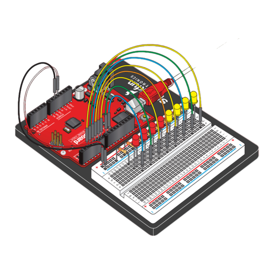
- Page 35 CIRCUIT #4 PIN 2 Multiple LEDs PIN 3 RedBoard PIN 4 PIN 5 So you have gotten one LED to blink on and o – LEDs fantastic! Now it's time to up the stakes a little bit – by (Light-Emitting Diodes) connecting EIGHT LEDS AT ONCE.
- Page 36 RESET DIGITAL (PWM~) LEARN. SHARE. HACK. POWER ANALOG IN Page 34...
- Page 37 Page 35...
- Page 38 Arduino Code: Circuit 2 Open Arduino IDE File > Examples > SIK Guide > Circuit # 4 Code to Note: When you have to manage a lot of variables, an "array" is a handy way to group them together. Here we're creating int ledPins[] = {2,3,4,5,6,7,8,9};...
- Page 39 CIRCUIT #5 Circuit 2 Circuit 2 Push Buttons 5 volt Up until now, we’ve focused solely on outputs. Now we’re going to go to the other end of spectrum and play around with inputs. In this circuit, we’ll be Resistors (10K ohm) looking at one of the most common and simple (Brown-Black-Orange) RedBoard...
- Page 40 RESET DIGITAL (PWM~) LEARN. SHARE. HACK. POWER ANALOG IN Page 38...
- Page 41 Page 39...
- Page 42 Arduino Code: Circuit 2 Open Arduino IDE File > Examples > SIK Guide > Circuit # 5 Code to Note: e digital pins can be used as inputs as well as outputs. pinMode(button2Pin, INPUT); Before you do either, you need to tell the RedBoard which direction you're going.
- Page 43 CIRCUIT #6 Circuit 2 Photo Resistor So you’ve already played with a potentiometer, which 5 volt varies resistance based on the twisting of a knob. In this circuit, you’ll be using a photo resistor, which PIN 9 changes resistance based on how much light the Photocell sensor receives.
- Page 44 RESET RESET DIGITAL (PWM~) DIGITAL (PWM~) LEARN. SHARE. HACK. POWER POWER ANALOG IN ANALOG IN Page 42...
- Page 45 Page 43 Page41...
- Page 46 Arduino Code: Circuit 2 Open Arduino IDE File > Examples > SIK Guide > Circuit # 6 Code to Note: lightLevel = map(lightLevel, 0, 1023, 0, 255); When we read an analog signal using analogRead(), it will be Parameters a number from 0 to 1023. But when we want to drive a map(value, fromLow, fromHigh, toLow, toHigh) PWM pin using analogWrite(), it wants a number from 0 to 255.
- Page 47 CIRCUIT #7 Circuit 2 Temperature Sensor 5 volt A temperature sensor is exactly what it sounds like – a TMP36 sensor used to measure ambient temperature. particular sensor has three pins – a positive, a ground, (Precision Temperature Sensor) and a signal. is is a linear temperature sensor.
- Page 48 RESET DIGITAL (PWM~) POWER ANALOG IN Page 46...
- Page 49 Page 47...
- Page 50 Arduino Code: Circuit 2 Open Arduino IDE File > Examples > SIK Guide > Circuit # 7 Code to Note: Before using the serial monitor, you must call Serial.begin() to initialize it. 9600 is the "baud rate", or communications speed. When Serial.begin(9600);...
- Page 51 CIRCUIT #8 Circuit 2 A Single Servo Servos are ideal for embedded electronics applications No junction dot means no connection because they do one thing very well that motors cannot – they can move to a position accurately. By varying the 5 volt pulse width of the output voltage to a servo, you can move a servo to a speci c position.
- Page 52 RESET DIGITAL (PWM~) POWER ANALOG IN Page 50...
- Page 53 Page 51...
- Page 54 Arduino Code: Circuit 2 Open Arduino IDE File > Examples > SIK Guide > Circuit # 8 Code to Note: #include is a special "preprocessor" command that inserts a library (or any other le) into your sketch. You can type this command yourself, or #include <Servo.h>...
- Page 55 CIRCUIT #9 Flex Sensor In this circuit, we will use a ex sensor to measure, well, ex! A ex sensor uses carbon on a strip of 5 volt plastic to act like a variable resistor, but instead of changing the resistance by turning a knob, you change it by exing (bending) the component.
- Page 56 RESET DIGITAL (PWM~) LEARN. SHARE. HACK. POWER ANALOG IN Page 54...
- Page 57 Page 55...
- Page 58 Arduino Code: Circuit 2 Open Arduino IDE File > Examples > SIK Guide > Circuit # 9 Code to Note: Because the ex sensor / resistor combination won't give us a full 0 to 5 volt range, we're using the map() function as a servoPosition = map(flexPosition, 600, 900, 0, 180);...
- Page 59 CIRCUIT #5 CIRCUIT #10 Circuit 2 Circuit 2 Soft Potentiometer RedBoard In this circuit, we are going to use yet another kind of PIN 11 variable resistor – this time, a soft potentiometer (or PIN 10 soft pot). is is a thin and exible strip that can 5 volt detect where pressure is being applied.
- Page 60 RESET DIGITAL (PWM~) POWER ANALOG IN Page 58...
- Page 61 Page 59...
- Page 62 Arduino Code: Circuit 2 Open Arduino IDE File > Examples > SIK Guide > Circuit # 10 Code to Note: These big, scary functions take a single Value (RGBposition) and calculate the redValue = constrain(map(RGBposition, 0, 341, 255, 0), 0, 255) three RGB values necessary to create a + constrain(map(RGBposition, 682, 1023, 0, 255), 0, 255);...
- Page 63 CIRCUIT #11 Circuit 2 Piezo Buzzer In this circuit, we'll again bridge the gap between the Piezo Buzzer digital world and the analog world. We'll be using a buzzer that makes a small "click" when you apply voltage to it (try it!). By itself that isn't terribly exciting, but if you turn the voltage on and o hundreds of times a second, the buzzer will produce a RedBoard...
- Page 64 RESET DIGITAL (PWM~) LEARN. SHARE. HACK. POWER ANALOG IN Page 62...
- Page 65 Page 63...
- Page 66 Arduino Code: Circuit 2 Open Arduino IDE File > Examples > SIK Guide > Circuit # 11 Code to Note: Up until now we've been working solely with numerical data, but the Arduino can also work with text. Characters (single, printable, char notes[] = "cdfda ag cdfdg gf ";...
- Page 67 CIRCUIT #12 Circuit 2 Spinning a Motor 5 volt Remember before when you played around with a servo motor? Now we are going to tackle spinning a motor. is requires the use of a transistor, which can switch a Diode larger amount of current than the RedBoard can.
- Page 68 RESET DIGITAL (PWM~) LEARN. SHARE. HACK. POWER ANALOG IN Page 66...
- Page 69 Page 67...
- Page 70 Arduino Code: Circuit 2 Open Arduino IDE File > Examples > SIK Guide > Circuit # 12 Code to Note: e RedBoard's serial port can be used to receive as well as send data. Because data could arrive at any time, the RedBoard stores, or "bu ers"...
- Page 71 CIRCUIT #5 CIRCUIT #13 Circuit 2 Circuit 2 Relays In this circuit, we are going to use some of the lessons we learned in circuit 12 to control a relay. A relay is basically 5 volt Resistor (330 ohm) an electrically controlled mechanical switch. Inside that (Orange-Orange-Brown) harmless looking plastic box is an electromagnet that, when it gets a jolt of energy, causes a switch to trip.
- Page 72 RESET DIGITAL (PWM~) POWER ANALOG IN Page 70...
- Page 73 Page 71...
- Page 74 Arduino Code: Circuit 2 Open Arduino IDE File > Examples > SIK Guide > Circuit # 13 Code to Note: When we turn on the transistor, which in turn energizes the relay's coil, the relay's switch contacts are closed. is connects the digitalWrite(relayPin, HIGH);...
- Page 75 CIRCUIT #14 Circuit 2 Shift Register Now we are going to step into the world of ICs (integrated 5 volt circuits). In this circuit, you’ll learn all about using a shift Resistors (330 ohm) register (also called a serial-to-parallel converter). e shift (Orange-Orange-Brown) PIN 2...
- Page 76 RESET DIGITAL (PWM~) POWER ANALOG IN Page 74...
- Page 77 Page 75...
- Page 78 Arduino Code: Circuit 2 Open Arduino IDE File > Examples > SIK Guide > Circuit # 14 Code to Note: You'll communicate with the shift register (and a lot of other parts) using an interface called SPI, or Serial Peripheral Interface. is interface uses a data line and a separate clock line that work together to move data in or out of shiftOut(datapin, clockpin, MSBFIRST, data);...
- Page 79 CIRCUIT #5 CIRCUIT #15 Circuit 2 Circuit 2 In this circuit, you’ll learn about how to use an LCD. An LCD, or liquid crystal display, is a simple screen 16x2 LCD that can display commands, bits of information, or readings from your sensor - all depending on how you 5 volt program your board.
- Page 80 RESET DIGITAL (PWM~) LEARN. SHARE. HACK. POWER ANALOG IN Page 78...
- Page 81 Page 79...
- Page 82 Arduino Code: Circuit 2 Open Arduino IDE File > Examples > SIK Guide > Circuit # 15 Code to Note: is bit of code tells your Arduino IDE to include the library for a #include <LiquidCrystal.h> simple LCD display. Without it, none of the commands will work, so make sure you include it! is is the rst time you’ll re something up on your screen.
- Page 83 CIRCUIT #5 CIRCUIT #16 Circuit 2 Circuit 2 Simon Says Piezo Buzzer Now that we've learned all the basics behind the components in the SIK, let's put them together and RedBoard PIN 7 have some fun. is circuit will show you how to PIN 4 create your own Simon Says game.
- Page 84 RESET DIGITAL (PWM~) LEARN. SHARE. HACK. POWER ANALOG IN Page 82...
- Page 85 Page 83...
- Page 86 Arduino Code: Circuit 2 Open Arduino IDE File > Examples > SIK Guide > Circuit #16 Code to Note: e #de ne statement is used to create constants in your code. Constants are variables that will likely only have one value during the lifespan of your code. us, you can assign #define constants a value, and then use them throughout your code wherever you need them.
- Page 87 Going Further Visit us Online: Tis is just the beginning of your exploration into embedded electronics and coding. Our website has a wealth of tutorials to whet your appetite for more knowledge. We also host a community of hackers, engineers, DIYers, etc. in our forums. For additional circuits, projects, and expansion packs for your Inventor’s Kit, please visit our website! www.sparkfun.com/SIK...
- Page 88 10k ohm resistors © SparkFun Electronics, inc. All rights reserved. The SparkFun Inventor’s kit for the SparkFun RedBoard features, specifications, system requirements and availability are subject to change without notice. All other trademarks contained herein are the property of their respective owners.
Need help?
Do you have a question about the LAB-14302 and is the answer not in the manual?
Questions and answers