Advertisement
Quick Links
Advertisement

Subscribe to Our Youtube Channel
Related Manuals for Sparkfun Electronics RedBoard


Summary of Contents for Sparkfun Electronics RedBoard
- Page 1 SIK GUIDE Your guide to the SparkFun Inventor’s Kit for the SparkFun RedBoard Version 3.2...
- Page 2 Table of Contents Welcome to the SparkFun Inventor’s Guide e SparkFun Inventor's Guide is your map for navigating the waters of beginning embedded electronics. is booklet contains all the information you will need to explore the 16 circuits of the SparkFun Inventor's Kit for Educators.
- Page 3 Section 1: Getting Started What is the RedBoard platform? Download Arduino Software (IDE) Install Drivers Select your board: Arduino Uno Download “SIK Guide Code” Section 2: Getting Started with Circuits The World Runs on Circuits Inventory of Parts RedBoard Breadboard...
- Page 4 A Computer for the Physical World e RedBoard in your hand (or on your desk) is your development platform. At its roots, the RedBoard is essentially a small portable computer. It is capable of...
- Page 5 RedBoard Bug Zapper Counter Camera Time-lapse operation Auto-Coffee Maker Old Toy Email Notifer Auto-Plant Watering Quadcopter Power-Lacing High Tops Re-Programmed Traffic Light Page 3...
- Page 6 Download the Arduino IDE (Integrated Development Environment) Access the Internet In order to get your RedBoard up and running, you'll need to download the newest version of the Arduino software rst from www.arduino.cc (it's free!). is software, known as the Arduino IDE, will allow you to program the board to do exactly what you want.
- Page 7 // Connect your RedBoard to your Computer Use the USB cable provided in the SIK kit to connect the RedBoard to one of your computer’s USB inputs. // Install Arduino Drivers Depending on your computer’s operating system, you will need to follow speci c instructions.
- Page 8 Open the Arduino IDE software on your computer. Poke around and get to know the interface. We aren’t going to code right away, this is just an introduction. step is to set your IDE to identify your RedBoard. Page 6...
- Page 9 Compiles and approves your code. It will catch errors in syntax (like missing semi-colons or parenthesis). See Diagram Below Upload: Sends your code to the RedBoard. When you click it, you should see the lights on your board blink rapidly. See Diagram Below New: This buttons opens up a new code window tab.
- Page 10 Arduino UNO are interchangeable but you won’t find the RedBoard listed in the Arduino Software. Select “Arduino UNO” instead. Select the serial device of the RedBoard from the Tools | com3 or higher Serial Port menu. is is likely to be (COM1 and COM2 are usually reserved for hardware serial ports).
- Page 11 Download Arduino Code (For use with the circuits in this guide) Type in the following URL to download the code: sparkfun.com/sikcode Start Programs arduino examples Unzip the le “SIK Guide Code”. It should be located in your browser’s Copy the “SIK Guide Code” folder into Arduino’s “Downloads”...
- Page 12 Getting Started with Circuits What is an Electrical Circuit? A circuit is basically an electrical loop with a starting point and an ending point - with any number of components in between. Circuits can include resistors, diodes, inductors, sensors of all sizes and shapes, motors, and any other handful of hundreds of thousands of components.
- Page 13 Page 11...
- Page 14 Inventory of Parts Jumper Wire (5mm) Various Colors (Light Emitting Diode) 330 Resistor 10K Resistor * ACTUAL SIZE * ACTUAL SIZE Potentiometer Diode (1N4148) * ACTUAL SIZE Photo Resistor Piezo Buzzer Temp. Sensor Transistor (TMP36) (P2N2222AG) FRONT FRONT BACK BACK DC Motor DC Motor Push Button...
- Page 15 Flex Sensor SparkFun RedBoard 7-15V Soft Potentiometer AREF IOREF RESET 3.3V Servo Breadboard Breadboard Standard Solderless Standard Solderless (Color may vary) a b c d e a b c d e f g h i f g h i Relay...
- Page 16 7-15V AREF 3 4 5 IOREF RESET 3.3V Page 14...
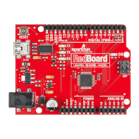
- Page 17 (Indicates RedBoard is ON) - This is a simple power indicator LED. Reset Button - This is a way to manually reset your RedBoard, which makes your code restart. ICSP Pins (Uploading Code without Bootloader) - This is for "In-Circuit Serial Programming," used if you want to bypass the bootloader.
- Page 18 a b c d e f g h i a b c d e f g h i This line divides the board in half, restricting electricity to one half or the other. Page 16...
- Page 19 Breadboard Vertical Connection (+ Power and - Ground) - Power bus See Diagram Below Making a Connection: Horizontal Connection ( a-e & f-j) See Diagram Below) Above the breadboard How’s it all connected? CONNECTED! a b c d e f g h i Power: Each + sign runs power anywhere in the vertical column.
- Page 20 5V can’t hurt you, so don’t be afraid to touch anything in your circuit. You can also power the RedBoard through the barrel jack.
- Page 21 Components like resistors need to have necessary to use the black holder for the their legs bent into 90° angles in order to RedBoard and breadboard, but we correctly fit the breadboard sockets. You recommend it for the first time inventor! can also cut the legs shorter to make them easier to work with on the breadboard.
- Page 22 RESET DIGITAL (PWM~) LEARN. SHARE. HACK. POWER ANALOG IN Page 20...
- Page 23 Page 21...
- Page 24 Open Your First Sketch: Open Up the Arduino IDE software on your computer. Coding in the Arduino language will control your circuit. Open the code for Circuit 1 by accessing the “SIK Guide Code” you downloaded and placed into your “Examples” folder earlier. File Edit Sketch Tools Help...
- Page 25 IDE changes it from text into instructions the computer Verify can understand. is sends the instructions via the USB cable to the computer chip on the RedBoard. Upload RedBoard will then begin running your code automatically. // The result of a completed circuit with correct code after verified and uploaded.
- Page 26 Upload your code. Begin to understand how the Arduino code works. See below. Before you can use one of the RedBoard's pins, you need to tell the pinMode(13, OUTPUT); RedBoard whether it is an INPUT or OUTPUT. We use a built-in "function"...
- Page 27 CIRCUIT #2 Circuit 2 Circuit 2 Potentiometer PIN 13 RedBoard In this circuit you’ll work with a potentiometer. 5 volt A potentiometer is also known as a variable resistor. When it’s connected with 5 volts across its two outer (Light-Emitting Diode)
- Page 28 RESET DIGITAL (PWM~) LEARN. SHARE. HACK. POWER ANALOG IN Page 26...
- Page 29 Page 27...
- Page 30 Arduino Code: Circuit 2 Open Arduino IDE File > Examples > SIK Guide > Circuit # 2 Code to Note: A “variable” is a stored value you’ve given a name to. You must introduce, or "declare" variables before you use them; here we're declaring a variable int sensorValue;...
- Page 31 CIRCUIT #3 Circuit 2 RGB LED PIN 11 PIN 10 RedBoard You know what’s even more fun than a blinking LED? Changing colors with one LED. RGB, or PIN 9 red-green-blue, LEDs have three di erent color-emit- ting diodes that can be combined to create all sorts of colors.
- Page 32 RESET DIGITAL (PWM~) LEARN. SHARE. HACK. POWER ANALOG IN Page 30...
- Page 33 Page 31...
- Page 34 If it's not true, the code within the second brackets {} will run. e RedBoard is very very fast, capable of running thousands of lines of code each second. To slow it down so that we can see what it's doing, delay(sensorValue);...
- Page 35 Now it's time to up the stakes a little bit – by (Light-Emitting Diodes) connecting EIGHT LEDS AT ONCE. We'll also give Resistors (330 ohm) our RedBoard a little test by creating various lighting (Orange-Orange-Brown) sequences. is circuit is a great setup to start practicing...
- Page 36 RESET DIGITAL (PWM~) LEARN. SHARE. HACK. POWER ANALOG IN Page 34...
- Page 37 Page 35...
- Page 38 Arduino Code: Circuit 2 Open Arduino IDE File > Examples > SIK Guide > Circuit # 4 Code to Note: When you have to manage a lot of variables, an "array" is a handy way to group them together. Here we're creating int ledPins[] = {2,3,4,5,6,7,8,9};...
- Page 39 PIN 13 inputs – a push button. e way a push button works PIN 3 PIN 2 with RedBoard is that when the button is pushed, the voltage goes LOW. e RedBoard reads this and (Light-Emitting Diode) Buttons reacts accordingly. In this circuit, you will also use a...
- Page 40 RESET DIGITAL (PWM~) LEARN. SHARE. HACK. POWER ANALOG IN Page 38...
- Page 41 Page 39...
- Page 42 Code to Note: e digital pins can be used as inputs as well as outputs. pinMode(button2Pin, INPUT); Before you do either, you need to tell the RedBoard which direction you're going. To read a digital input, you use the digitalRead() button1State = digitalRead(button1Pin);...
- Page 43 PIN 9 changes resistance based on how much light the Photocell sensor receives. Since the RedBoard can’t directly (Light Sensitive Resistor) interpret resistance (rather, it reads voltage), we use a (Light-Emitting Diode) voltage divider to use our photo resistor.
- Page 44 RESET RESET DIGITAL (PWM~) DIGITAL (PWM~) LEARN. SHARE. HACK. POWER POWER ANALOG IN ANALOG IN Page 42...
- Page 45 Page 43 Page41...
- Page 46 Arduino Code: Circuit 2 Open Arduino IDE File > Examples > SIK Guide > Circuit # 6 Code to Note: lightLevel = map(lightLevel, 0, 1023, 0, 255); When we read an analog signal using analogRead(), it will be Parameters a number from 0 to 1023. But when we want to drive a map(value, fromLow, fromHigh, toLow, toHigh) PWM pin using analogWrite(), it wants a number from 0 to 255.
- Page 47 TMP36 sensor has a nominal 750 mV at 25°C (about RedBoard room temperature). In this circuit, you’ll learn how to integrate the temperature sensor with your RedBoard, and use the Arduino IDE’s serial monitor to display the temperature. When you’re building the circuit be careful not...
- Page 48 RESET DIGITAL (PWM~) POWER ANALOG IN Page 46...
- Page 49 Page 47...
- Page 50 Arduino Code: Circuit 2 Open Arduino IDE File > Examples > SIK Guide > Circuit # 7 Code to Note: Before using the serial monitor, you must call Serial.begin() to initialize it. 9600 is the "baud rate", or communications speed. When Serial.begin(9600);...
- Page 51 For example, a pulse of 1.5 milliseconds will move the servo 90 degrees. In this circuit, you’ll learn how to use PWM (pulse width modulation) PIN 9 to control and rotate a servo. RedBoard (Ground) Servo Wire Page 49...
- Page 52 RESET DIGITAL (PWM~) POWER ANALOG IN Page 50...
- Page 53 Page 51...
- Page 54 Fits and Starts If the servo begins moving then twitches, and there's a ashing light on your RedBoard, the power supply you are using is not quite up to the challenge. Using a wall adapter instead of USB should solve this problem.
- Page 55 PIN 9 PIN A0 more it bends, the higher the resistance gets; it has a RedBoard range from about 10K ohm to 35K ohm. In this Flex Sensor circuit we will use the amount of bend of the ex sensor to control the position of a servo.
- Page 56 RESET DIGITAL (PWM~) LEARN. SHARE. HACK. POWER ANALOG IN Page 54...
- Page 57 Page 55...
- Page 58 Arduino Code: Circuit 2 Open Arduino IDE File > Examples > SIK Guide > Circuit # 9 Code to Note: Because the ex sensor / resistor combination won't give us a full 0 to 5 volt range, we're using the map() function as a servoposition = map(flexposition, 600, 900, 0, 180);...
- Page 59 CIRCUIT #5 CIRCUIT #10 Circuit 2 Circuit 2 Soft Potentiometer RedBoard In this circuit, we are going to use yet another kind of PIN 11 variable resistor – this time, a soft potentiometer (or PIN 10 soft pot). is is a thin and exible strip that can 5 volt detect where pressure is being applied.
- Page 60 RESET DIGITAL (PWM~) POWER ANALOG IN Page 58...
- Page 61 Page 59...
- Page 62 Arduino Code: Circuit 2 Open Arduino IDE File > Examples > SIK Guide > Circuit # 10 Code to Note: These big, scary functions take a single Value (RGBposition) and calculate the redValue = constrain(map(RGBposition, 0, 341, 255, 0), 0, 255) three RGB values necessary to create a + constrain(map(RGBposition, 682, 1023, 0, 255), 0, 255);...
- Page 63 (try it!). By itself that isn't terribly exciting, but if you turn the voltage on and o hundreds of times a second, the buzzer will produce a RedBoard tone. And if you string a bunch of tones together, you've got music!
- Page 64 RESET DIGITAL (PWM~) LEARN. SHARE. HACK. POWER ANALOG IN Page 62...
- Page 65 Page 63...
- Page 66 Arduino Code: Circuit 2 Open Arduino IDE File > Examples > SIK Guide > Circuit # 11 Code to Note: Up until now we've been working solely with numerical data, but the Arduino can also work with text. Characters (single, printable, char notes[] = "cdfda ag cdfdg gf ";...
- Page 67 Now we are going to tackle spinning a motor. is requires the use of a transistor, which can switch a Diode larger amount of current than the RedBoard can. When (1N4148) DC Motor using a transistor, you just need to make sure its maximum specs are high enough for your use.
- Page 68 RESET DIGITAL (PWM~) LEARN. SHARE. HACK. POWER ANALOG IN Page 66...
- Page 69 Page 67...
- Page 70 Circuit # 12 Code to Note: e RedBoard's serial port can be used to receive as well as send data. Because data could arrive at any time, the RedBoard stores, or "bu ers" data coming into the port until you're ready to use it.
- Page 71 In Diode this circuit, you’ll learn how to control a relay like a pro (1N4148) – giving your RedBoard even more powerful abilities! SPDT Relay LEDs RedBoard (Light-Emitting Diodes)
- Page 72 RESET DIGITAL (PWM~) POWER ANALOG IN Page 70...
- Page 73 Page 71...
- Page 74 Arduino Code: Circuit 2 Open Arduino IDE File > Examples > SIK Guide > Circuit # 13 Code to Note: When we turn on the transistor, which in turn energizes the relay's coil, the relay's switch contacts are closed. is connects the digitalWrite(relayPin, HIGH);...
- Page 75 (also called a serial-to-parallel converter). e shift (Orange-Orange-Brown) PIN 2 register will give your RedBoard an additional eight outputs, PIN 3 using only three pins on your board. For this circuit, you’ll practice by using the shift register to control eight LEDs.
- Page 76 RESET DIGITAL (PWM~) POWER ANALOG IN Page 74...
- Page 77 Page 75...
- Page 78 1 or 0 to turn the LEDs on or o . e RedBoard has several commands, such as bitWrite(), that make this easy to do. What You Should See:...
- Page 79 CIRCUIT #5 CIRCUIT #15 Circuit 2 Circuit 2 In this circuit, you’ll learn about how to use an LCD. An LCD, or liquid crystal display, is a simple screen 16x2 LCD that can display commands, bits of information, or readings from your sensor - all depending on how you 5 volt program your board.
- Page 80 RESET DIGITAL (PWM~) LEARN. SHARE. HACK. POWER ANALOG IN Page 78...
- Page 81 Page 79...
- Page 82 Arduino Code: Circuit 2 Open Arduino IDE File > Examples > SIK Guide > Circuit # 15 Code to Note: is bit of code tells your Arduino IDE to include the library for a #include <LiquidCrystal.h> simple LCD display. Without it, none of the commands will work, so make sure you include it! is is the rst time you’ll re something up on your screen.
- Page 83 Circuit 2 Simon Says Piezo Buzzer Now that we've learned all the basics behind the components in the SIK, let's put them together and RedBoard PIN 7 have some fun. is circuit will show you how to PIN 4 create your own Simon Says game. Using some LEDs,...
- Page 84 RESET DIGITAL (PWM~) LEARN. SHARE. HACK. POWER ANALOG IN Page 82...
- Page 85 Page 83...
- Page 86 Arduino Code: Circuit 2 Open Arduino IDE File > Examples > SIK Guide > Circuit #16 Code to Note: e #de ne statement is used to create constants in your code. Constants are variables that will likely only have one value during the lifespan of your code. us, you can assign #define constants a value, and then use them throughout your code wherever you need them.
- Page 87 Learning More Visit us Online: is is just the beginning of your exploration into embedded electronics and coding. Our website has a wealth of tutorials to whet your appetite for more knowledge. We also host a community of hackers, engineers, DIYers, etc. in our forums. So log on to our website for more information about Arduino, or to plan ahead for your next project! www.sparkfun.com...
- Page 88 10k ohm resistors © SparkFun Electronics, inc. All rights reserved. The SparkFun Inventor’s kit for the SparkFun RedBoard features, specifications, system requirements and availability are subject to change without notice. All other trademarks contained herein are the property of their respective owners.
Need help?
Do you have a question about the RedBoard and is the answer not in the manual?
Questions and answers