
Related Manuals for aerl CoolMax SRX-R Series


Summary of Contents for aerl CoolMax SRX-R Series
- Page 1 CoolMax SRX-R Charge Controller Installation and Operation Manual Models SRX-R 450/55-48 SRX-R 600/70-48...
- Page 2 CoolMax SRX-R Charge Controller User Manual © 2023 by AERL Pty. Ltd. All Rights Reserved. Trademark AERL and the AERL Logo are trademarks owned by AERL Holdings Pty. Ltd. and used by AERL Pty. Ltd under license. These trademarks may be registered in Australia and other countries.
-
Page 3: Table Of Contents
Programming the Device ........................... 12 Device Status Indicator ..........................13 Battery Charge Profile ..........................14 Charge Profile Configuration ....................... 15 Setting the Battery Charge Profile with AERL Link ................16 Ground Fault Detection ..........................18 Ground Fault Sensitivity ..........................19 Communications Protocols ........................20 Troubleshooting –... - Page 4 • AERL will not be held responsible in any way for the mishandling of this product or for installation of the product in a manner that does not follow the instructions in this manual or as advised by an AERL technician.
-
Page 5: Warranty Conditions
AERL will bear the cost of parts and labour to repair any manufacturing faults found within the terms and period of this warranty and pay the cost of freight to return the repaired CoolMax SRX-R controller within Australia/New Zealand but the method of freight will be determined by AERL. -
Page 6: Specifications
USER MANUAL COOLMAX SRX-R – Rack Mount Australian Energy Research Labs AER09-R – Rev 1.0.0 May 2023 Specifications General Specifications Parameter Typical Weight 4 kg Dimensions (H x W x D) 432 x 192 x 78 mm Enclosure Type Indoor Type 1 / IP20 Input / Output Power Connectors Backplane Connector Characteristics... -
Page 7: Introduction
PV array, efficiently charging your batteries and maximizing power generation. AERL’s Maximum Power Point Tracking (MPPT) algorithm has been proven to be highly robust, resistant to local extremes, and results in power losses of less than 0.5% over the whole operating temperature range of a PV Array. -
Page 8: Installation
All installations must comply with national and local electrical standards and codes of practice, and the CoolMax SRX-R must be installed in a clean, dry location away from direct sunlight. AERL always recommends professional installation. No on-going maintenance is required. -
Page 9: Mounting The Shelf
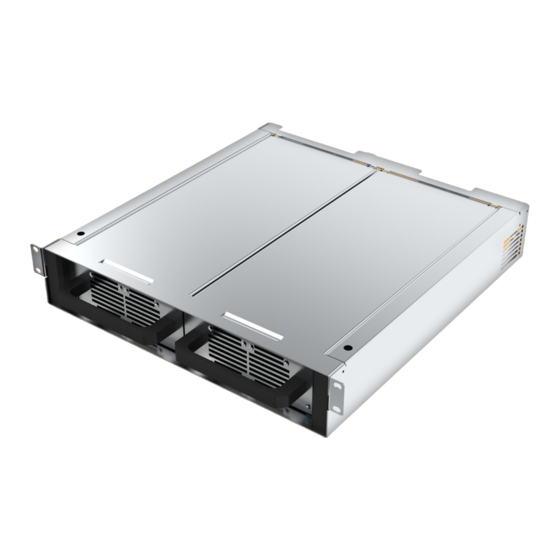
USER MANUAL COOLMAX SRX-R – Rack Mount Australian Energy Research Labs AER09-R – Rev 1.0.0 May 2023 Mounting the Shelf The SRX-R shelf must be mounted horizontally in a suitably ventilated lockable cabinet ensuring the backplane area is restricted to licensed electricians and qualified technicians. Figure 1: SRX-R Modules in Shelf AER09-R REV 1.0.0... -
Page 10: Wiring Information
USER MANUAL COOLMAX SRX-R – Rack Mount Australian Energy Research Labs AER09-R – Rev 1.0.0 May 2023 Wiring Information This section will provide information and instructions for safely wiring up the DC connections on the CoolMax SRX-R. Wire and Disconnect Sizing IMPORTANT •... -
Page 11: Backplane Terminations
USER MANUAL COOLMAX SRX-R – Rack Mount Australian Energy Research Labs AER09-R – Rev 1.0.0 May 2023 Backplane Terminations CAUTION – Equipment Damage Reversing the polarity of the output may damage the CoolMax SRX-R and void product warranty. Confirm polarity with a multi-meter prior to closing the input and output circuit breakers. COMMS RJ45 x 2 (IN/OUT) -
Page 12: Operation
Figure 4 to the right. Note - The USB Selection Switch must be toggled between MPPT 1 and MPPT 2. The AERL Link Software for Windows 10/11 can be downloaded at the URL below. Figure 3: USB-B Programming Port and Toggle Switch link.aerl.com.au... -
Page 13: Device Status Indicator
USER MANUAL COOLMAX SRX-R – Rack Mount Australian Energy Research Labs AER09-R – Rev 1.0.0 May 2023 Device Status Indicator Green Blue START-UP / SLEEP Yellow CHARGER DISABLED / SETUP REQUIRED FAULT Figure 4: LED Indication States AER09-R REV 1.0.0... -
Page 14: Battery Charge Profile
The SRX-R operates using an advanced three-stage charging process and has pre-set charge voltage profiles for each supported nominal battery voltage. That said, AERL always recommends referring to the battery manufacturers specifications regarding charge voltages for optimal battery life and performance. -
Page 15: Charge Profile Configuration
USER MANUAL COOLMAX SRX-R – Rack Mount Australian Energy Research Labs AER09-R – Rev 1.0.0 May 2023 Charge Profile Configuration The CoolMax SRX-R allows for extensive flexibility when it comes to charge profile parameters to suit numerous different modern battery chemistries and manufacturers requirements. Our programmable charge profile allows for the configuration of the Battery Charge Rate, and the Absorb, Float, Re-Bulk, and Equalization voltage points. -
Page 16: Setting The Battery Charge Profile With Aerl Link
AER09-R – Rev 1.0.0 May 2023 Setting the Battery Charge Profile with AERL Link Connect to the USB-B Port on the backplane, ensuring the USB Change-Over Switch (refer to Figure 2 on Page 11) is set to the device you wish to program. Within a few seconds, the device will appear in the available local devices list in AERL Link. - Page 17 USER MANUAL COOLMAX SRX-R – Rack Mount Australian Energy Research Labs AER09-R – Rev 1.0.0 May 2023 Once the required settings have been set, slide the charger enabled toggle to the right, and apply the changes to the CoolMax SRX-R by clicking on the Apply button to begin charging. AER09-R REV 1.0.0...
-
Page 18: Ground Fault Detection
Figure 10: Chassis Earth Point IMPORTANT The system earth configuration (Ground Fault Mode) must be adjusted in the AERL Link software for use with functionally earthed systems otherwise an earth fault will be detected on the earthed pole. -
Page 19: Ground Fault Sensitivity
The SRX-R ground fault detection offers three levels of sensitivity, all of which are compliant with the Australian PV installation standards. 100kΩ Medium 50kΩ High 30kΩ The sensitivity of the ground fault detection can be configured in AERL Link as demonstrated in Figure 11 below. Figure 11: Ground Fault Sensitivity Adjustment AER09-R REV 1.0.0... -
Page 20: Communications Protocols
Communications Protocols The CoolMax SRX-R features both Controller Area Network (CAN bus) and ModBus RTU (RS485) compatible protocols for remote monitoring and control functionality. The relevant protocol registry maps for integration are available from AERL on request. Both networking protocols can be accessed via the RJ45 connectors located inside the access cover. -
Page 21: Troubleshooting - Error Codes
Warning LED Code Warning Description Recommended Action Code The initial setup Connect and configure the process has not been device with the AERL Link Flashing Device Not completed and the Software. Yellow/Green Configured device will not begin charging. Refer to Page 14. - Page 22 No Output No output has been Power cycle the device and -350 1 Flash - Red Detected detected. contact AERL if it reoccurs. The device’s internal Internal systems have reached a The device will automatically -1100 Solid Red Temperature critical temperature and restart when it’s safe to do so.
- Page 23 The battery temperature Consider increasing the battery sensor has detected a high temperature compensation High Battery 8 Flashes - battery temperature. factor with the AERL Link -1102 Temperature Operating the battery at a Software or reducing the Detected high temperature will greatly ambient environment reduce its lifespan.
Need help?
Do you have a question about the CoolMax SRX-R Series and is the answer not in the manual?
Questions and answers