
Related Manuals for aerl CoolMax SRX


Summary of Contents for aerl CoolMax SRX
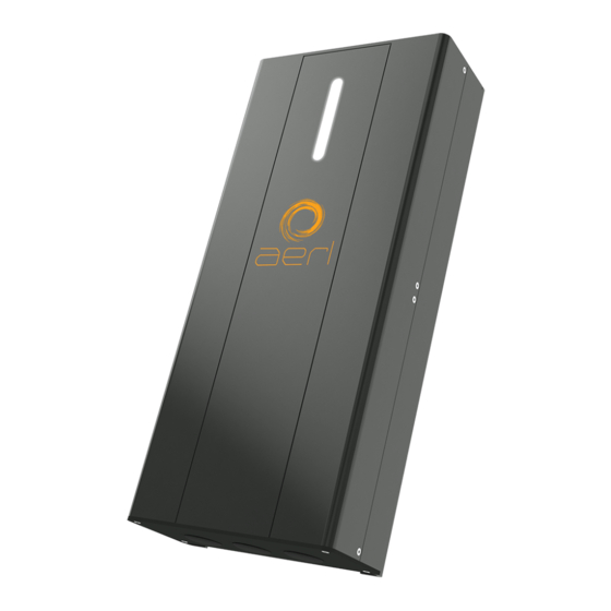
- Page 1 CoolMax SRX Charge Controller Installation and Operation User Manual Models SRX 600/70-48 SRX 600/35-120...
- Page 2 The “Power Optimizer” would eventually come to be known as the AERL MAXIMIZER™, the world’s first truly Universal Maximum Power Point Tracker (MPPT). Today, AERL manufactures a range of highly reliable and efficient specialised power electronic controllers for use in Solar, Micro Hydro, Micro Wind and Cathodic Protection applications.
-
Page 3: Table Of Contents
Device Status Indicator ........................... 15 Battery Charge Profile ..........................16 Charge Profile Configuration ......................17 Setting the Battery Charge Profile with AERL Link ................. 18 Battery Temperature Compensation....................20 Connecting the Temperature Sensor ......................20 Temperature Sensor Location ........................20 Communications Protocols ........................ - Page 4 • AERL will not be held responsible in any way for the mishandling of this product or for installation of the product in a manner that does not follow the instructions in this manual or as advised by an AERL technician.
-
Page 5: Warranty Conditions
In the event of the product being out of service, AERL shall bear no responsibility for any consequential loss or expense. AERL will not be held responsible for any misleading or incorrect information conveyed by anyone not directly employed by AERL. -
Page 6: Specifications
USER MANUAL COOLMAX SRX – Wall Mount Australian Energy Research Labs AER09 – Rev 1 January 2022 Specifications General Specifications Parameter Typical Weight 5 kg Dimensions (L x W x H) 432 x 192 x 89 mm Enclosure Type Indoor Type 1 / IP20... -
Page 7: Introduction
PV array, efficiently charging your batteries and maximizing power generation. AERL’s Maximum Power Point Tracking (MPPT) algorithm has been proven to be highly robust, resistant to local extremes, and results in power losses of less than 0.5% over the whole operating temperature range of a PV Array. -
Page 8: Installation
Installation IMPORTANT The CoolMax SRX must be installed in a clean, dry location away from direct sunlight. Optimal cooling is achieved when the COOLMAX SRX is mounted vertically. A minimum of 15cm should be kept clear above the COOLMAX SRX to allow for cooling. -
Page 9: Mounting The Controller
USER MANUAL COOLMAX SRX – Wall Mount Australian Energy Research Labs AER09 – Rev 1 January 2022 Mounting the Controller Use the mounting plate included with the controller to mount the SRX on a vertical surface as demonstrated in Figure 1A below. -
Page 10: Mounting Clearances
USER MANUAL COOLMAX SRX – Wall Mount Australian Energy Research Labs AER09 – Rev 1 January 2022 Mounting Clearances When mounting the SRX, a clearance zone around the device must be adhered to for optimal cooling of the controller under full load. Please refer to the Figure 1B below. -
Page 11: Wiring Information
Australian Energy Research Labs AER09 – Rev 1 January 2022 Wiring Information This section will provide information and instructions for safely wiring up the CoolMax SRX. Wire and Disconnect Sizing IMPORTANT • Wire sizes must comply with local and national standards. Input conductors and circuit breakers must be rated at 1.56 times the short-circuit current of the PV array. -
Page 12: Wiring Compartment
Drilling any holes into the unit will void all product warranty. To install cabling, the access panel of the COOLMAX SRX must be removed. This is done by removing the two M4 countersunk Phillips screws on the bottom of the enclosure and the four M3 countersunk Phillips screws on either side of the access panel. -
Page 13: Wiring Polarity
January 2022 Wiring Polarity CAUTION – Equipment Damage Reversing the polarity of either the input or output may damage the CoolMax SRX and void product warranty. Confirm polarity with a multi-meter prior to closing the input and output circuit breakers. -
Page 14: Operation
The CoolMax SRX will power up when a PV voltage above 30Vdc is applied. When the COOLMAX SRX is first powered the on, the device will run a self-test and then the LED Indication strip will appear yellow to indicate no charge profile has been configured. -
Page 15: Device Status Indicator
USER MANUAL COOLMAX SRX – Wall Mount Australian Energy Research Labs AER09 – Rev 1 January 2022 Device Status Indicator Green Blue SLEEP Yellow WARNING | WAIT FAULT Figure 5: LED Indication States AER09 REV 1... -
Page 16: Battery Charge Profile
Over-The-Air firmware updates. The CoolMax SRX charge output will not automatically activate for safety reasons. Prior to activating the charge output, the charge profile must be configured for the relevant battery solution being utilized. -
Page 17: Charge Profile Configuration
January 2022 Charge Profile Configuration The CoolMax SRX allows for extensive flexibility when it comes to charge profile parameters to suit numerous different modern battery chemistries and manufacturers requirements. Our programmable charge profile allows for the configuration of the Battery Charge Rate, and the Absorb, Float, Re-Bulk, and Equalization voltage points. -
Page 18: Setting The Battery Charge Profile With Aerl Link
AER09 – Rev 1 January 2022 Setting the Battery Charge Profile with AERL Link Connect to the USB-C Port on the CoolMax and Select the Device from the available local devices list. Select the Settings button to access the battery charging settings. Charge settings are changed by clicking on the setting value and using the plus/minus arrows or the keyboard to enter a new value. - Page 19 AER09 – Rev 1 January 2022 Once the required settings have been set, Apply the Changes to the CoolMax SRX by clicking on the Apply button. Note - Further instructions for more complex functionality can be found in the AERL Link User Manual.
-
Page 20: Battery Temperature Compensation
A temperature compensation value must be set in the charge profile before the CoolMax SRX will begin to utilize the battery temperature. To connect your remote temperature sensor to the CoolMax SRX, plug the sensor into one of the CAN RJ45 ports labelled “CAN” and located between the power terminals. -
Page 21: Communications Protocols
AER09 – Rev 1 January 2022 Communications Protocols The CoolMax SRX features both Controller Area Network (CAN bus) and ModBus RTU (RS485) capabilities for remote monitoring and control functionality. The relevant protocol registry maps for integration are available from AERL on request. -
Page 22: Troubleshooting - Error Codes
January 2022 Troubleshooting – Error Codes If the CoolMax SRX detects an issue, an alarm will be triggered. Please refer to the table below for Warning Codes starting with “W” and the table located on Pg. 23 for Fault Codes starting with “F”. - Page 23 USER MANUAL COOLMAX SRX – Wall Mount Australian Energy Research Labs AER09 – Rev 1 January 2022 Please refer to the table below for Fault Codes. Fault Error Description Recommended Action Code Please contact your A hardware fault has been...
- Page 24 USER MANUAL COOLMAX SRX – Wall Mount Australian Energy Research Labs AER09 – Rev 1 January 2022 Fault Error Description Recommended Action Code High PV Voltage has been detected. Confirm PV String Configuration F008 High PV Voltage The device has shutdown to prevent is appropriate for the device.
- Page 25 USER MANUAL COOLMAX SRX – Wall Mount Australian Energy Research Labs AER09 – Rev 1 January 2022 Note: The CoolMax troubleshooting guide and documentation is being improved regularly. If the relevant situation is not documented, please contact AERL. AER09 REV 1...
- Page 26 USER MANUAL COOLMAX SRX – Wall Mount Australian Energy Research Labs AER09 – Rev 1 January 2022 This page has intentionally been left blank. AER09 REV 1...
- Page 27 USER MANUAL COOLMAX SRX – Wall Mount Australian Energy Research Labs AER09 – Rev 1 January 2022 This page has intentionally been left blank. AER09 REV 1...
Need help?
Do you have a question about the CoolMax SRX and is the answer not in the manual?
Questions and answers