
Subscribe to Our Youtube Channel
Related Manuals for Massimo MS624


Summary of Contents for Massimo MS624
- Page 1 24” SNOW BLOWER MS624 Operation Manual This safety alert symbol identifies important safety messages in this manual. Failure to follow this important safety information may result in serious injury or death.
-
Page 3: Table Of Contents
Table of Contents Important Safety Information .............4 Overview ..................7 Assembly ..................8 Filling with Gasoline and Oil ............10 Operation Precautions ..............11 Operation Controls ..............13 Operation ..................14 Maintenance .................16 Troubleshooting ................24 Storage ..................27 Warranty and Specifications .......... Back Cover... -
Page 4: Important Safety Information
Important Safety Information Important Safety Information WARNING WARNING: Read and thoroughly understand all instructions and safety information before operating this snow blower. Failure to do so may cause serious injury or death. Do not allow anyone to operate this snow blower who has not read this manual. As with all power equipment, a snow blower can be dangerous if used improperly. - Page 5 Important Safety Information General Safety Failure to follow warnings, cautions, assembly and operation instructions in the Operation Manual may result in serious injury or death. DANGER READ THE OPERATION MANUAL BEFORE OPERATION. • Do not permit children to operate this equipment at any time. Do not permit others that have not read and understood the complete Operation Manual to operate this equipment.
- Page 6 Important Safety Information Safety Decals Safety labels on the snow blower are to remind you of important information while you are operating the unit. Make sure all safety warning decals are attached and in readable condition. Replace missing or defaced decals. Contact Dirty Hand Tools at 1-877-487-8275 for replacement decals.
-
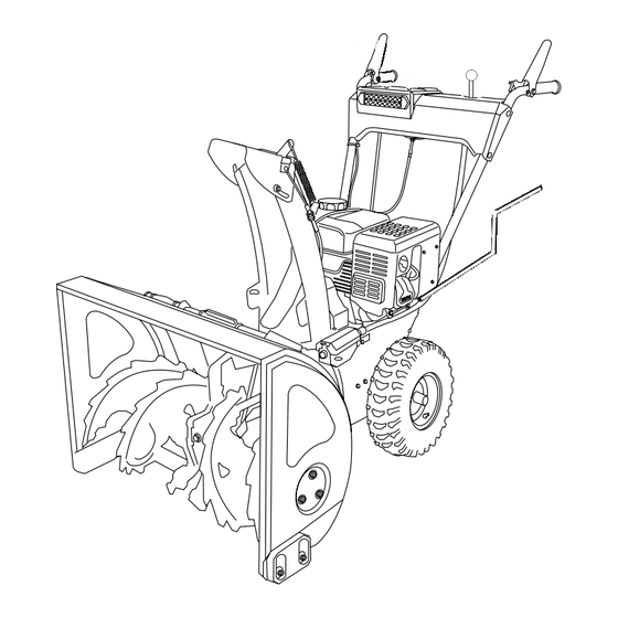
Page 7: Overview
Overview Your snow blower requires some assembly. Save the packing materials and box for future use as a storage container. COMPLETELY READ AND UNDERSTAND THE OPERATOR’S MANUAL BEFORE ATTEMPTING TO OPERATE THE SNOW BLOWER. DRIVE HEATED SHIFT AUGER CONTROL HANDLES LEVER CONTROL LEVER... -
Page 8: Assembly
Assembly Handlebar and Contol Assembly 1. Hex bolts and nylon lock nuts have been provided in a hardware package. Align the two holes at each end of the handlebar with the two holes in the handlebar support on the snow blower. Push hex bolts through from the outside and secure with a nylon lock nut on the interior in two places on both sides of the snow blower (see Figure 1). - Page 9 Assembly DISCHARGE Attaching the Discharge Chute CHUTE 1. Attach the discharge chute to the snow blower by placing it on the chute seat on the snow blower. Position the flange keeper beneath the chute seat lip. Align the two holes in the chute and two holes in the flange keeper and secure with two bolts from the top side (see Figure 4).
-
Page 10: Filling With Gasoline And Oil
Filling with Gasoline and Oil WARNING FUEL IS HIGHLY FLAMMABLE AND POISONOUS ALWAYS FILL THE TANK WITH ENGINE OFF AND COOL. ALWAYS CHECK THE FUEL LEVEL BEFORE OPERATING. Allow the engine to cool for at least two minutes before To prevent serious injury and fire: removing the fuel cap. -
Page 11: Operation Precautions
Operation Precautions DANGER COMPLETELY READ AND UNDERSTAND THIS MANUAL BEFORE ATTEMPTING TO OPERATE THE SNOW BLOWER 1. Keep all safety guards in place and in proper working order at all times. 2. NEVER place fingers, hands, or body near the snow blower when it is running. - Page 12 Operation Precautions CAUTION DISENGAGE ALL CONTROL LEVERS AND STOP THE ENGINE BEFORE YOU LEAVE THE OPERATING POSITION. Wait until the auger/impeller comes to a complete stop before unclogging the chute assembly, making any adjustments, or inspections. 1. Exercise caution to avoid slipping or falling, especially when operating in reverse.
-
Page 13: Operation Controls
Operation Control SHIFT LEVER AUGER DRIVE CONTROL CONTROL LEVER LEVER CHUTE HEIGHT CHUTE CONTROL DIRECTION CONTROL Figure 7 Shift Lever The shift lever controls the direction of travel and ground speed. There are five forward speeds. Position one (1) is the slowest and position five (5) is the fastest. -
Page 14: Operation
Operation PRIMER IGNITION CHOKE BUTTON CAUTION FILL WITH OIL BEFORE STARTING Make sure the auger control and drive control are in the disengaged (released) position. Recoil Starter 1. To start a cold engine, move the choke to the CHOKE position (to the left). To restart a warm engine, leave the Choke in the RUN position (to the right). - Page 15 Operation Engaging the Drive and Auger Controls 1. With the choke control in the open position, move shift lever into one of the four forward (F) or one reverse (R) positions. Select a speed appropriate for the snow conditions and a pace you’re comfortable with.
-
Page 16: Maintenance
Maintenance WARNING BEFORE PERFORMING ANY MAINTENANCE PROCEDURE STOP THE ENGINE, WAIT FIVE (5) MINUTES TO ALLOW ALL PARTS TO COOL. Disconnect the spark plug wire, keeping it away from the spark plug. Regular maintenance is the way to ensure the best performance and long life of your machine. - Page 17 Maintenance WARNING TO PREVENT SERIOUS INJURY FROM ACCIDENTAL STARTING TURN THE POWER SWITCH OF THE ENGINE TO ITS “OFF” POSITION. Wait for the engine to cool, and remove the spark plug wire before performing any inspection, maintenance, or cleaning procedures. Spark Plug Maintenance: Spark Plug Gap 1.
- Page 18 Maintenance WARNING OIL IS VERY HOT DURING OPERATION AND CAN CAUSE BURNS. WAIT FOR ENGINE TO COOL BEFORE CHANGING OIL. Wait for the engine to cool, and remove the spark plug wire before performing any inspection, maintenance, or cleaning procedures. Changing the engine oil SAE VISCOSITY GRADES 1.
- Page 19 Maintenance LUBRICATION Gear Shaft The gear (hex) shaft should be lubricated at least once a season or after every 20 hours of operation. 1. Remove the lower frame cover by removing the two screws which secure it (see Figure 12). 2.
- Page 20 Maintenance Shear Pin Replacement The auger is attached to the spiral shaft with shear pins SHEAR secured with cotter pins. If the auger should strike a foreign object or ice jam, the snow blower is designed to shear off those pins (see Figure 15). If the auger will not rotate, check if the pins have been sheared.
- Page 21 Maintenance Auger Belt Replacement 1. Remove the belt cover on the front of the engine by removing the two self-tapping screws (see Figure 17). Drain the gasoline from the snow blower, or place a container to catch leakage from the gas cap. 2.
- Page 22 Maintenance Drive Belt Replacement 1. Remove the belt cover on the front of the engine by removing the two self-tapping screws (see Figure 17). Drain the gasoline from the snow blower, or place a container to catch leakage from the gas cap. DRIVE BELT 2.
- Page 23 Maintenance Control Wire Adjustment CONTROL When the auger or drive belts are adjusted or replaced, or after LEVER a long time of use, the control wires may need to be adjusted. The control wires for the drive control and the auger control are attached to the auger lever and the drive lever on the handlebar.
-
Page 24: Troubleshooting
Engine Troubleshooting WARNING BEFORE PERFORMING ANY MAINTENANCE PROCEDURE STOP THE ENGINE, WAIT FIVE (5) MINUTES TO ALLOW ALL PARTS TO COOL. Disconnect the spark plug wire, keeping it away from the spark plug. PROBLEM SOLUTION The engine will not start. •... - Page 25 Snow Blower Troubleshooting PROBLEM SOLUTION No snow through blower’s discharge chute. • Discharge chute and/or auger is clogged • Disengage the auger and drive controls, stop the engine, wait ten seconds for the auger to stop rotating, then using the clean-out tool provided, remove the snow clogging the chute.
- Page 26 Snow Blower Troubleshooting PROBLEM SOLUTION Auger does not engage. • Auger control wire is too loose. • If there is too much slack in the auger control wire, the augers will not be engaged properly. Turn off the engine. Adjust the tension of the auger control wire (see page 23). •...
-
Page 27: Storage
Storage WARNING DO NOT STORE SNOW BLOWER WITH FUEL IN TANK INDOORS Do not store in poorly ventilated areas, or near furnace, water heater, clothes dryer or gas appliance. 1. For short term storage wait for the engine to cool, then CYLINDER clean the engine with a clean cloth. -
Page 28: Warranty And Specifications
Warranty & Specifications IMPORTANT NOTICE We, the manufacturer, reserve the right to change the product and/ or specifications in this manual without notification. The manual is for information usage only and the pictures and drawings depicted herein are for reference only. Warranty Repair and Service Do not return this product to the store for warranty issues or repair.
Need help?
Do you have a question about the MS624 and is the answer not in the manual?
Questions and answers