
Related Manuals for MiiS Horus Scop DSC 300


Summary of Contents for MiiS Horus Scop DSC 300
- Page 1 MiiS Horus Scope DSC 300 User Manual DOC. No. 82.0022-000001-01 Ver. D Date of issue: May, 2022 Copyright@2022 MiiS Inc. All right reserved.
-
Page 3: Table Of Contents
Contents Preparations ..................4 • Before use .................. 4 • Indication for Use ............... 4 • Contraindications ............... 4 • Names of components ............. 11 • Charging the battery ..............16 • Power indicator ................ 17 • Assembling ................18 •... -
Page 4: Preparations
Preparations Before use Prior to installation and start-up of the Horus Scope, carefully read the user manual. As with all technical devices, the proper function and safety operation of this device depend on the user complying with the safety recommendations described in these operating instructions. In addition, please make sure that it does not appear damaged or broken. - Page 5 Focus calibration A. Focus calibration of DEC 200 (→ 44) When using DEC 200 under the following conditions, focus calibration is necessary. • The last four digits of the serial number of the control unit and optical lens do not match.
- Page 6 Usage cautions and notes When in use The camera may become warm if used for long periods of time, but this is not its fault. Keep the camera as far away as possible from electromagnetic equipment (such as micro- wave ovens, TVs, video games, etc.). Do not use the camera near radio transmitters or high-voltage lines.
- Page 7 RELATIVE SPECTRAL DISTRIBUTION OF ILLUMINATION LIGHT Memory cards If you purchase different memory capacity of memory card, must be preceded format to FAT32. To prevent damage to cards and data: • Avoid high temperatures, direct sunlight, electromagnetic fields, and static electricity.
- Page 8 About the slit lamp jig: Attach the slit lamp jig only to slit lamp equipment that has been qualified by MiiS. Make sure the jig is completely locked by pushing it downward. The slit lamp jig is only suitable for DEC 200.
- Page 9 Disinfect the eyecup or rubber pad with CaviWipes. NOTE The device is not intended to be sterilized. Disinfect the control unit and charging station with CaviWipes). Maintenance Please check control unit and optical lens once every 3 months. It is the health care provider to protect patient health information and to meet regulatory and HIPAA compliance.
- Page 10 the manufacturer and the competent authority of the Member State in which the user and/or patient is established. This device has been tested and found to comply with the limits for medical devices to the IEC 60601-1-2: 2014. These limits are designed to provide reasonable protection against harmful interference in a standard medical installation.
-
Page 11: Names Of Components
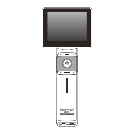
Model: SB 1 (free download) 10. Image Management System, Model: SD 1 standalone (option) 1. Eyecup Eye Fundus MiiS Horus Scope 2. MiiS Horus Portable Chin Rest: CR Camera DEC 200 100 (Optional) 3. Slit lamp jig (Optional) Eye Anterior MiiS Horus Scope 1. - Page 12 User interface Control Unit (MiiS Horus Scope DSC 300) Top view ›› Power button Lens lock Front view ›› 3.5” LCD touch panel Manual focus OK button: • Completely press down to take a photo • Back to photo/video mode while...
- Page 13 Bottom view ›› Mini USB Pogo pad Micro HDMI Strap hook Rear view ›› Lens assembling mark Cover glass and sensor Lens connecting pins Battery cover Repair hole Memory card slot...
- Page 14 Charging Station Mini USB connector...
- Page 15 Optical Lens of MiiS Horus Scope DEC 200 (Eye Fundus Camera) Optical Lens of MiiS Horus Scope DEA 200 (Eye Anterior Camera) Optical Lens of MiiS Horus Scope DGC 200 (Eye Surface Camera)
-
Page 16: Charging The Battery
Charging the battery Always charge before first use Prior to first use, insert the battery into the control unit and close the battery cover referred to the below section. Connect USB connector to the power adapter. Let the battery be charged for at least five hours. -
Page 17: Power Indicator
Power indicator Power indicator System Status Power off Power on Mixed blue Blinking blue Blinking blue Light color No Light Orange Light Blue Light Light Light orange Light Connect to PC Power less Normal Power less via USB cable Information Charging System off or enable USB... -
Page 18: Assembling
Assembling (Take Eye Fundus Camera as an example.) Step 1. ↘ Align the marks of the optical lens and control unit. Mark on the optical lens Mark Step 2. → Hold the optical lens and attach it to the control unit. Rotate and fasten the optical lens in a clockwise direction. -
Page 19: Using The Setup Mode
Using the Setup mode Turn on the power To turn on the system, press the power button (→ 12) to turn on the control unit. Approximately one to two seconds later, the boot screen will appear on the LCD panel. Note: When below conditions occur, user needs to turn off... - Page 20 Settings [Aiming Light/Capture Light] The default setting of [Aiming Light/Capture Light] is [IR/White LED]. In the setting, DEC 200 employs IR illumination for alignment and focusing to assure patient comfort. With IR, the user observes fundus images monochromatically. At the moment of pressing the shutter button, the system will turn on the white LED instantly.
- Page 21 [Standby] User can set standby mode to be on or off. Once the mode is on, the LCD panel will be turned off if the system is idle for three minutes. To touch the screen or press OK button to wake up the system. [Date Setting] User can change the current date setting from the screen.
- Page 22 Free UVC viewer is available in any search engine. [Quality check] User can turn on or turn off the quality check function. If quality check function is on, the device will take a few seconds to analyze the quality of the image and then the quality will be shown on the screen in preview and display mode.
- Page 23 [DICOM] Export image with or without DICOM format. [Factory Setting] User can recover the device to its factory settings. [Format SD Card] User can format the Memory Card (SD card). NOTE All information will be deleted after Memory Card is formatted. [Red Free Function] DEC 200 allows digital red free images to be created directly from the information of the initial color image.
- Page 24 After turn on red free function, it will take more than 3 seconds to do image process after shooting. And there is a red free switch icon at the left-down corner of image. By press the icon to switch image into red free mode. Wireless connection [Wi-Fi] User can turn on/off the Wi-Fi.
- Page 25 [Wi-Fi setting – AP Mode] User can select “AP mode” to connect to internet through an AP. [Upload to website – AP Mode] User can select “Upload setting” to set the URL, department and password.
- Page 26 After select the images and input the patient’s information, user can upload the data to website. [Wi-Fi setting – DIB 100] User can select “DIB 100” and connect DSC 300 with DIB 100 through Wi-Fi. [Transfer data to DIB 100] When DSC 300 is connected with DIB 100, user can select images and transfer to DIB 100.
- Page 27 Click the “switch” button to switch between the original image and processed one.
-
Page 28: Dea 200
B. DEA 200 Enter the Setup mode Using the [Setup] menu It is recommended that all setting items are set according to user’s requirements for first- time use. Bring up the [Setup] menu Touch the photo icon and then touch the setup icon. Exit the [Setup] menu Once a setting adjustment is made, the new value affects the system immediately. - Page 29 2. Exposure time from 1/30” to 1/120”. (Default: 1/60”) [Standby] User can set standby mode to be on or off. Once the mode is on, the LCD panel will be turned off if the system is idle for three minutes. To touch the screen or press OK button to wake up the system.
- Page 30 [UVC] While connecting DSC 300 to a computer via USB cable, the product works as a USB storage device. If UVC mode is on, pictures can be shown both on the LCD panel of the product and the screen of the computer. To display image on the computer, please install webcam application prior to enabling UVC mode.
- Page 31 [Factory Setting] User can recover the device to its factory settings. Wireless connection [Wi-Fi] User can turn on/off the Wi-Fi. [Wi-Fi setting – Direct Mode] User can select “Direct mode” and connect DSC 300 with PC through Wi-Fi directly. Click “Change” icon to change the password.
- Page 32 [Wi-Fi setting – AP Mode] User can select “AP mode” to connect to internet through an AP. [Upload to website – AP Mode] User can select “Upload setting” to set the URL, department and password.
- Page 33 After select the images and input the patient’s information, user can upload the data to website.
-
Page 34: Dgc 200
C. DGC 200 Enter the Setup mode Using the [Setup] menu It is recommended that all setting items are set according to user’s requirements for first- time use. Bring up the [Setup] menu Touch the photo icon and then touch the setup icon. Exit the [Setup] menu Once a setting adjustment is made, the new value affects the system immediately. - Page 35 [Date Setting] User can change the current date setting from the screen. [Time Setting] User can change the current time setting from the screen. [UVC] While connecting DSC 300 to a computer via USB cable, the product works as a USB storage device.
- Page 36 [Format SD Card] User can format the Memory card (SD card). NOTE All information will be deleted after memory card is formatted. [DICOM] Export image with or without DICOM format. [Factory Setting] User can recover the device to its factory settings. Wireless connection [Wi-Fi] User can turn on/off the Wi-Fi.
- Page 37 [Wi-Fi setting – Direct Mode] User can select “Direct mode” and connect DSC 300 with PC through Wi-Fi directly. Click “Change” icon to change the password. [Wi-Fi setting – AP Mode] User can select “AP mode” to connect to internet through an AP.
- Page 38 [Upload to website – AP Mode] User can select “Upload setting” to set the URL, department and password. After select the images and input the patient’s information, user can upload the data to website.
-
Page 39: Entering The Patient Id
Entering the patient ID Using patient ID as partial file name is supported in DSC 300. Create a new patient ID from scratch (DICOM off) By gently pressing the OK button, the user always goes back to a shooting mode, either photo or video mode;... - Page 40 Create a new patient ID on an existing one After a patient ID is set, the user can quickly create a new patient ID that is based on the existing ID plus 1 e.g., ABCDE12345 → ABCDE12346. File naming rule Product Name Model Name Picture Name...
- Page 41 Meaning of each symbol: Symbol Refer to Left eye photo taken by the eye fundus camera Right eye photo taken by the eye fundus camera Left eye photo taken by the eye anterior camera Right eye photo taken by the eye anterior camera Left eye photo taken by the eye surface camera Right eye photo taken by the eye surface camera Hour...
-
Page 42: Taking Pictures
Taking pictures A. DEC 200 Sequence of operations Step 1: Turn on the power Press the power button to turn on the control unit. Approximately one to two seconds later, the boot screen will appear on the LCD panel. After about 15 seconds, the information icons will appear on the top of the LCD panel. - Page 43 Notes If it’s difficult to activate auto-shooting, there are 2 options: 1. Let IR spot into the frame then completely press OK button to take a photo. 2. By tapping MF icon or pressing focus-adjustment buttons of the control unit ( ), to switch to manual focus mode.
- Page 44 Focus calibration Focus on an object at a distance of 5 meters or greater in MF mode. Please follow the steps to finish focus calibration of DEC 200. Step 1 Step 2 Step 3 Press FOCUS [+] button to Aim a target 5m away, and Long press the date and move focus to max value.
- Page 45 Examination conditions After the optical lens is attached to the control unit and setup is complete, the user can start taking images. Approaches for taking the image of human eye fundus are as follows: • Have the examinee stay in <5 lux dark room; in such an environment, a newspaper is nearly impossible to see.
-
Page 46: Dea 200
B. DEA 200 Sequence of operations Step 1: Turn on the power Press the power button to turn on the control unit. Approximately one to two seconds later, the boot screen will appear on the LCD panel. After about 15 seconds, the information icons will appear on the top of the LCD panel. - Page 47 Holding position Hold the control unit with one hand and use the other hand to hold the lighting track. Maintain the lens at the same height of the eye being examined. To stabilize the lens, rest the track on the part of the hand between the thumb and index finger and put your middle and index fingers on the examinee’s forehead, as showed in the left image.
- Page 48 Step 3: Tighten screw A in clockwise direction to correction rod hole (under shaft circle hole). screw A Step 4: Remove rubber pad of forehead stopper. rubber pad Step 5: Assemble correction plate to the front end of inner axis. Inner axis correction plate Step 6: Tighten screw B in clockwise direction to fix correction rod on DEA 200.
- Page 49 Focus calibration Step 1: Move Slit Module far away from Zoom lens (more than 30 degrees), then rotate position of Zoom lens to Tele (16x) end. Zoom lens Tele Wide Slit Module Step 2: Enter to Auto-calibration mode by screen. Step 3: Half press OK button to active auto focus function.
- Page 50 Step 5: Long press the date and time till it changes to “Save Motor Position” to finish calibration. Step 6: Remove the Correction Rod and start to use the device with the best image quality. Assembling of Forehead Stopper Step 1: Remove screw A in counter-clockwise direction Screw A Step 2: Rolling the inner axis and the shaft to find out forehead stopper hole.
- Page 51 Step 4: Remove correction plate from the front end of inner axis. correction plate Step 5: Assemble rubber pad to the front end of inner axis. rubber pad Step 6: Tighten screw B in clockwise direction to fix correction rod on DEA 200. screw B...
-
Page 52: Dgc 200
C. DGC 200 Sequence of operations Step 1: Turn on the power Press the power button to turn on the control unit. Approximately one to two seconds later, the boot screen will appear on the LCD panel. After about 15 seconds, the information icons will appear on the top of the LCD panel. -
Page 53: Photo Mode
Photo mode The device’s default setting is “photo mode.” User can take a picture or video in “photo mode” or “video mode,” respectively. Photo mode: For DEC 200, the default setting of “Aiming Light/Capture Light” is “IR/White LED”. Therefore, the image before pressing the OK button is monochrome color. When a picture is just taken, the screen shows the result image in full color in auto review mode. -
Page 54: Video Mode
Video mode Video mode: Completely press the OK button to start recording. Press again to end recording. For DEC 200, the default setting of “Aiming Light/Capture Light” is “IR/White LED.” During the video shooting, user can press “the brightness adjustment key +” to enhance the white LED for two seconds. -
Page 55: Playback
Playback Display mode Touch the photo icon and then the display icon to see the photos that have been taken. Display mode: Click the left or right arrow symbols to go to the previous or next photo, respectively. Click the up or down arrow symbol to backward in days or forward in days. Zoom in and out on the photo while in display photo. - Page 56 Deleting pictures Tap the delete icon to delete the image. By using the delete functions on your camera, this only changes the file management information and does not completely delete the data from the memory card. When disposing of or transferring your memory cards, we recommend physically destroying them or using commercially available computer data erasing software to completely delete the data from the card.
-
Page 57: Chin Rest
Chin Rest Scope Set up Device The Height Adjustment of Chin Rest and Scope Use chin rest paper for each new patient. Ensure that the examinee has not placed his/her hand or fingers under the chin rest. Otherwise, hand or fingers may be hurt. -
Page 58: Miscellaneous
Miscellaneous File transferring Transfer images to an electronic device (e.g., personal computer, laptop, or mobile phone) via the USB cable or memory card. It is the health care provider to protect patient health information and to meet regulatory and HIPAA compliance. The images on DSC 300 may contain identifiable patient information and it is the responsibility of the health care provider to ensure that data safeguards are implemented to protect patient health information. -
Page 59: Technical Description
Technical description MiiS Horus Scope DSC 300, control unit: Focus Auto & manual focus Picture Resolution 2560 x 1920 pixels Video Resolution 2560 x 1920 pixels LCD Monitor 3.5” TFT LCD Image Format JPEG (Photograph) and H.264 (Video) Interface Mini USB 2.0, Micro HDMI (1.4), Wi-Fi (2,4G) File Transfer Mini USB Port to PC with USB cable 1.5±0.3m (Shield) -
Page 60: Liability
• Slit Width Selection:≤0.2, 0.2, 0.5, 2.0, 5.0, Φ10 mm • Filter:Transparent, cobalt blue, red-free (Green) • Light:Conform to group II of ISO 15004-2:2007 • Weight:580grams (Typical) MiiS Horus Scope DGC 200, Eye Surface Camera: • View Angle:21 degrees • Dimension:10.7 x 9 x 20.3cm (Typical) •... -
Page 61: Symbols And Standards
Symbols and standards Symbols CAUTION The caution statements in this manual identify conditions or practices that could result in damage to the equipment or other property, or loss of data. Type BF-Indicates this is a product with Type BF applied parts. The device is complying with IEC 60601-1:2005. - Page 62 GS1 Data Matrix Medical Device Medical Prescription only Direct current Power button Recycling lithium-ion batteries Specific Battery Recycling Disposal noncontaminated electrical electronic equipment This product had an internal rechargeable battery with a Class II power supply. Keep away from sunlight Hand with care Fragile This side up...
- Page 63 Standards IEC 60601-1:2005+A1:2012 (EN 60601- Electrical safety 1:2006+A1:2013) IEC 60601-1-2:2014 EMC and regulatory compliance (EN 60601-1-2:2015) Ophthalmic instruments-Fundamental ISO 15004-2:2007 requirements and test methods Part 2: Light hazard protection Ophthalmic instruments - Fundamental requirements and test methods - Part 1: ISO 15004-1:2006 General requirements applicable to all ophthalmic instruments...
- Page 64 並改善至無干擾時方得繼續使用。 前項合法通信,指依電信法規定作業之無線電通信。 低功率射頻電機須忍受合法通信或工業、科學及醫療用電波輻射性電機設備之干擾。 The device is designed and tested to meet the applicable limits for radio frequency (RF) exposure established by the Federal Communications Commission (U.S.A.) Specific Absorption Rate; (SAR) refers to the rate at which the body absorbs RF energy. The minimum allowable SAR distance is 5 mm, and the maximum allowable SAR limit is 4.0 W/kg, averaged over 10 gram of tissue for the device.
- Page 65 Guidance and manufacturer's declaration - electromagnetic immunity The device is intended for use in the electromagnetic environment specified below. The customer or the user of the device should assure that it is used in such an environment. Immunity test IEC 60601 test level Compliance level Electromagnetic environment - guidance Floor should be wood, concrete or ceramic...
- Page 66 The minimum separation distance for higher immunity test levels shall be calculated using the following equation: , where P is the maximum power in watts (W),d is the minimum separation distance meters [m), and Fis the immunity test level in V/m. Please visit www.miis.com.tw for more information.
- Page 67 Medimaging Integrated Solution Inc. 3F., No.24-2, Industry E. Rd. IV, Hsinchu Science Park, Hsinchu,Taiwan 30077, R.O.C. Tel: +886-3-5798860 / 5798865 Fax: +886-3-5798821 Web: http://www.miis.com.tw/ MedNet EC-REP GmbH Borkstrasse 10, 48163 Münster, Germany...
Need help?
Do you have a question about the Horus Scop DSC 300 and is the answer not in the manual?
Questions and answers