Table of Contents
Advertisement
Quick Links
Advertisement
Table of Contents

Related Manuals for LumaSense technologies MC320


Summary of Contents for LumaSense technologies MC320
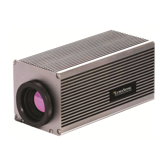
- Page 1 MC320 Thermal Imager...
- Page 2 Confidential Information The material contained herein consists of information that is the property of LumaSense Technologies and intended solely for use by the purchaser of the equipment described in this manual. All specifications are subject to change without notice. Changes are made periodically to the information in this publication, and these changes will be incorporated in new editions.
-
Page 3: Table Of Contents
Infrared Radiation ....................19 Emissivity....................... 20 Blackbody Radiation ..................... 20 Blackbody Type Source and Emissivity ..............22 Determining Emissivity ..................23 Background Noise ....................25 Practical Measurement ..................25 Emissivity of Various Materials ................27 MC320 Thermal Imager Manual Contents... - Page 4 Appendix ........................31 Specifications ......................31 5.1.1 MC320 Variations ....................31 5.1.2 Optics ........................31 5.1.3 Technical Data...................... 31 5.1.4 Dimensions ......................32 Contents MC320 Thermal Imager Manual...
-
Page 5: General Information
This manual provides important information about the instrument and can be used as a work of reference for installing, operating, and maintaining your MC320 Thermal Imager. It is important that you carefully read the information contained in this manual and follow all safety procedures before you install or operate the instrument. -
Page 6: Disposal / Decommissioning
Operation shall not resume until the condition causing the harmful interference has been corrected. 1.4 Disposal / Decommissioning Inoperable thermal imagers must be disposed of in compliance with local regulations for electro or electronic material. General Information MC320 Thermal Imager Manual... -
Page 7: Limit Of Liability And Warranty
LumaSense Technologies is not liable for any damages that arise from the use of any examples or processes mentioned in this manual or in case the content of this document should be incomplete or incorrect. - Page 8 To ensure consistent document formatting, this page was intentionally left blank. General Information MC320 Thermal Imager Manual...
-
Page 9: Introduction
2.1 System Overview The MC320 is intended to be integrated with the appropriate application-specific imaging components for use in process control, nondestructive testing, and diagnostic applications. It provides real-time digital image transfer and control using Gigabit Ethernet and provides an option for remote monitoring through a Local Area Network. -
Page 10: Camera Interfaces
2.2 Camera Interfaces 2.2.1 Rear Panel The rear panel of the MC320 supports connectors for the Gigabit Ethernet, BNC video output, Trigger, and DC Power input and mounting. Trigger Input BNC Video Out... -
Page 11: Lenses
2.3 Lenses Caution: The MC320 is a process camera that has a full array of optional lenses available to meet the needs of most applications. However, Do not use thinners, because of the extreme and application-specific nature of the benzene or other... -
Page 12: Storage
If Technical Support concludes that the instrument must be returned to LumaSense Technologies for repair, they will issue a Return Material Authorization (RMA) number. Return the instrument upon receipt of the RMA number, transportation prepaid. -
Page 13: Shipments To Lumasense For Repair
The instrument must be shipped in the original packing container or its equivalent. LumaSense Technologies is not responsible for freight damage to instruments that are improperly packed. Clearly indicate the assigned RMA number on the shipping package exterior. - Page 14 To ensure consistent document formatting, this page was intentionally left blank. Introduction MC320 Thermal Imager Manual...
-
Page 15: Getting Started
System Configuration and Wiring drawing supplied with the system. 3.1 Making the Connections Caution: In order for the MC320 system to operate correctly, the supplied Because the MC320 hardware must be properly attached to the computer and power system is designed for supplied to the various parts of the system. -
Page 16: Connecting The Camera To A Dedicated Computer
3.4.1 Connecting the Camera to a Dedicated Computer Connecting the MC320 to a computer using a crossover cable To Connect the Camera to a Dedicated Computer: 1. Connect one end of the RJ45 (Ethernet) crossover cable to the Ethernet port on the camera and the other end to the computer. -
Page 17: Connecting The Camera To A Network Device
3.4.2 Connecting the Camera to a Network Device Connecting the MC320 to a computer using a patch cable To Connect the Camera to a Network Device: 1. Connect one end of an RJ45 Ethernet patch cable to the Ethernet port on the camera and the other end to the Note: switch. -
Page 18: Installing The Software
3.6.2 LED Indicators The MC320 provides three LED indicators. The POWER LED indicates that the camera has power. The COMM LED indicates that the camera has an Ethernet connection. The TRIGGER LED indicates that the Trigger is active (future capability). -
Page 19: Principle Of Thermal Imaging
The wavelength of the infrared radiation ‘band’ is 0.78 to 1000µm (micrometers). This is longer than the wavelength of visible light yet shorter that radio waves. The wavelengths of infrared radiation are classified from the near infrared to the far infrared. MC320 Thermal Imager Manual Principle of Thermal Imaging... -
Page 20: Emissivity
The emissivity of a body is defined formally by the equation below as the ratio of the radiant energy emitted by the body to the radiation, which would be emitted by a blackbody at the same temperature. Principle of Thermal Imaging MC320 Thermal Imager Manual... - Page 21 In order to find out the wavelength on the maximum spectral radiant emittance, differentiate Planck’s law and take the value to 0. The equation is called “Wien’s displacement law”. MC320 Thermal Imager Manual Principle of Thermal Imaging...
-
Page 22: Blackbody Type Source And Emissivity
A law closely t = transmissivity related to the blackbody is Kirchhoff’s law that defines reflection, r = reflectivity transmission, absorption and radiation. e = emissivity a = e = 1 Principle of Thermal Imaging MC320 Thermal Imager Manual... -
Page 23: Determining Emissivity
The emissivity of the measured object must be internally corrected to 1 by the thermal imager). Therefore, in order to perform correct measurement for true temperature, the emissivity is determined as follows: MC320 Thermal Imager Manual Principle of Thermal Imaging... - Page 24 But since the painted object will not provide a complete blackbody, the emissivity of the painted object needs to be set first and then the temperature can be measured. The following figure shows examples of blackbody paint. Principle of Thermal Imaging MC320 Thermal Imager Manual...
-
Page 25: Background Noise
3. Then set the emissivity correcting function of thermal imager so that the temperature of the blackbody part and the measured surface will be the same. The obtained emissivity will be the emissivity of the measured surface. MC320 Thermal Imager Manual Principle of Thermal Imaging... - Page 26 But one must be careful about the number of reflections and/or the measuring angle. A small change in angle will reduce the emissivity enhancement. Measuring by Wedge effect Principle of Thermal Imaging MC320 Thermal Imager Manual...
-
Page 27: Emissivity Of Various Materials
4.8 Emissivity of Various Materials From “Infrared Radiation, a Handbook for Applications” by Mikael A. Bramson MC320 Thermal Imager Manual Principle of Thermal Imaging... - Page 28 Principle of Thermal Imaging MC320 Thermal Imager Manual...
- Page 29 MC320 Thermal Imager Manual Principle of Thermal Imaging...
- Page 30 Principle of Thermal Imaging MC320 Thermal Imager Manual...
- Page 31 2.55 lbs. (1 kg) (excludes any protective housing or optional lenses) Operating Position: Any operating position Housing: 6063 T5 Aluminum Alloy. Finish is alodine, clear, MIL-DTL-5541F, RoHS Compliant Dimensions: 3.25 in x 3.25 in x 7.75 in (83 mm x 83 mm x 197 mm) MC320 Thermal Imager Manual Appendix...
- Page 32 Power supply, communication, and IOs are isolated from each other Scope of delivery Includes 2 meter Ethernet crossover cable, 2 meter power supply cable, power supply unit (100…240 VAC, 47…63 Hz), lens cap, manual (on CD), carrying case, LumaSpec RT Viewer software. 5.1.4 Dimensions Appendix MC320 Thermal Imager Manual...
Need help?
Do you have a question about the MC320 and is the answer not in the manual?
Questions and answers