Table of Contents
Advertisement
Quick Links
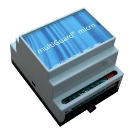
multiGuard® micro
Remote control and alarm via GSM
INDHOLD
1. SYSTEM DESCRIPTION ................................................... 2
2. MOUNTING ................................................................... 3
Prepare the central unit .................................. 3
Install SIM-card ............................................... 3
Electric mounting ............................................ 3
DIP switches for analog inputs ........................ 3
3. PREPARE PC .................................................................. 4
3.1 Connect PC ............................................... 4
3.3 Find Com-number ..................................... 4
4. INSTALLATION OF PC-PROGRAM .................................. 5
Window 1: Modem ......................................... 6
Window 2: Receiver(s) .................................... 7
Window 3: Inputs ............................................ 8
6. SETTING UP WITH SMS ................................................ 13
Shift PIN-code ............................................... 13
Lost password ............................................... 13
Deactivate password ..................................... 13
Setting up receiver(s) .................................... 13
Delete receiver .............................................. 14
Setting up zone for receiver .......................... 14
Approve telephone numbers ......................... 14
Change the priority of receivers .................... 14
6.1 SETTING UP DIGITAL INPUT ....................................... 14
Set up text ..................................................... 14
Send alarm only if text is entered .................. 14
Set up zone for digital input .......................... 15
Set up filter on input ..................................... 15
Use input for counting pulses ........................ 15
Activate 24V ................................................. 16
Execute command in text field ...................... 16
6.2 SET UP ANALOG INPUTS ........................................... 16
6.3 SETTING UP OUTPUT ................................................. 17
Profort A/S • Gunnar Clausens Vej 3 DK 8260 Viby J • Tel. +45 70233600 Fax +45 70233601 • E-mail: info@profort.com www.profort.dk
Manual
Activate output in case of alarm ................... 17
Set up macro ................................................. 17
Record IR-code .............................................. 18
Transmit IR-code ........................................... 18
6.4 SYSTEM MESSAGES AND ALARMS ............................ 18
Acknowledge command ................................ 18
Send status message ..................................... 19
Set time in the unit ........................................ 19
Text to and from serial port (RS232) ............. 19
Data communication with PLC ...................... 19
6.5 COMMANDS FOR SET-UP .......................................... 20
7. OPERATION ................................................................. 26
Connect/disconnect the unit .......................... 26
Control by SMS .............................................. 26
Control by DTMF ........................................... 26
Acknowledge alarm ...................................... 26
Requests to the unit ...................................... 26
Restore to default settings ............................ 27
9. FREQUENTLY ASKED QUESTIONS ................................ 29
10. SPECIFICATIONS ........................................................ 31
Ver. 2.02
Advertisement
Table of Contents

Related Manuals for MULTIGUARD micro

Summary of Contents for MULTIGUARD micro
-
Page 1: Table Of Contents
Manual Remote control and alarm via GSM Ver. 2.02 Activate output in case of alarm ....17 INDHOLD Set up macro ..........17 Record IR-code ..........18 1. SYSTEM DESCRIPTION ........... 2 Transmit IR-code ........... 18 ... -
Page 2: System Description
Mounting Remote control and alarm via GSM Ver. 2.02 1. S YSTEM DESCRIPTION Automatic alarm in case of sabotage and power The unit is used for controlling relays and data/alarm- failure (also in disconnected state). transmission via the GSM-network. It contains GSM- modem and a built-in antenna. -
Page 3: Mounting
Mounting Remote control and alarm via GSM Ver. 2.02 Connect outputs: 2. M OUNTING Relay-outputs are potential free relay contacts that The unit has a built-in GSM-modem. All types of SIM- break (NO) or make (NC) by means of instructions to cards can be used except from 3G cards. -
Page 4: Prepare Pc
Prepare PC Remote control and alarm via GSM Ver. 2.02 Notice that the next time you connect the 3. P REPARE USB-cable to either the same or another Start by connecting the serial converter and finding COM-port the given COM-number can have the COM-port number on the PC. -
Page 5: Installation Of Pc-Program
COM-port is selected, the unit is turned off or the RS232 cable is defect. If the text ’Connection to multiGuard’ doesn’t appear, you have to check if the correct COM-port has been selected. The installation runs automatically and 7. -
Page 6: Setting Up With "Quick-Setup
Setting up with Remote control and alarm via GSM Quick set-up Ver. 2.02 5. S ”Q ” ETTING UP WITH UICK SETUP Start Quick set-up on the PC and follow the set-up instructions through the 4 windows. The settings will be stored in unit’s ’flash memory’... -
Page 7: Window 2: Receiver(S)
Setting up with Remote control and alarm via GSM Quick set-up Ver. 2.02 Window 2: Receiver(s) It is possible to encode max. 25 receivers/ telephone numbers. Forward alarms Alarm messages can be forwarded as SMS, DTMF or E-mail. If you wish to receive both a SMS and an analog voice message it is necessary to set up the same telephone number twice. -
Page 8: Window 3: Inputs
Setting up with Remote control and alarm via GSM Quick set-up Ver. 2.02 Window 3: Inputs if the unit is not to be set up with user defined texts the unit will send the following standard messages in case of alarm: •... - Page 9 Setting up with Remote control and alarm via GSM Quick set-up Ver. 2.02 Zone ”Zone” is optional and can be used for locating alarms in categories, e.g. some alarms in zone 1 and other alarms in zone 2.
- Page 10 Setting up with Remote control and alarm via GSM Quick set-up Ver. 2.02 ’Activate digital input’: The input can be set to GND or 24 VDC mode. In GND mode the input is activated by a 0 VDC supply (GND) and input is closed. If the supply is removed inputs will open. In 24 VDC mode the input is activated by a 24 VDC supply and input will close.
- Page 11 Setting up with Remote control and alarm via GSM Quick set-up Ver. 2.02 Window 4: Output Setting up output ’Activate relay outputs on alarms’: Indicates if output must activate (close) in case of alarm and for how long. 10 sec., 20 sec., 40 sec., 1 min., 2 min., 4 min., 8 min., 15 min., Infinitely, Reflect inputs.
- Page 12 Setting up with Remote control and alarm via GSM Quick set-up Ver. 2.02 the unit sends the same power alarm as before after 30 min. and then shuts down. When the power returns the unit sends the standard text ‘Power Ok’.
-
Page 13: Setting Up With Sms
Setting up with SMS Remote control and alarm via GSM Ver. 2.02 telephone number. Otherwise the information is 6. S ETTING UP WITH not applied. The unit can be set up with SMS from a GSM- mobile phone. The set-up will then be Lost password transferred as SMS-commands. -
Page 14: Delete Receiver
Setting up with SMS Remote control and alarm via GSM Ver. 2.02 Sets up receiver nr. 4: e-mail (200= Telephone Calls are executed only to selected positions and company’s e-mail service). The E-mail address = in the listed order. -
Page 15: Set Up Zone For Digital Input
Setting up with SMS Remote control and alarm via GSM Ver. 2.02 Set up zone for digital input 1234 A0 Xy TEXT Sets up text for input x (x=0..7) on ’open/break’ Inputs can be put into zones in a way that with a filter in zone y (y=0..7). -
Page 16: Activate 24V
Setting up with SMS Remote control and alarm via GSM Ver. 2.02 Sets up minimum and maximum scale for 1234 Xx (x=0..9). measuring equipment: Sets up delay on message in x number of sec. Vx (x=1..2), min (-999..999) and max (- (standard is 2 sec.). -
Page 17: Setting Up Output
Setting up with SMS Remote control and alarm via GSM Ver. 2.02 6.3 S 1234 G0 ETTING UP OUTPUT Sets relay-outputs to not activate by alarm on Relay-output can be activated when the inputs inputs. changes their position. -
Page 18: Record Ir-Code
Setting up with SMS Remote control and alarm via GSM Ver. 2.02 1234 Delete macro 2 tones *60 (see the chap. ”Operating”). 1234 Mx x=0-9. Deletes macro x. Example: 1234 A0 SEND SIGNAL STRENGTH 6.4 S YSTEM MESSAGES AND ALARMS <OK>... -
Page 19: Send Status Message
Setting up with SMS Remote control and alarm via GSM Ver. 2.02 Sends alarm immediately in case of power Time controlled failure (after ca. 30 sec.) 9V rechargeable battery connection/disconnection must be installed. Requires that the time is set in the unit. -
Page 20: Commands For Set-Up
Code summary Remote control and alarm via GSM - Commands for set-up- Ver. 2.02 6.5 C OMMANDS FOR SET setting up The code summary below joins all commands used for the unit. These commands feeds the unit with information about what to do in case of alarm on an input, for instance who is supposed to receive the alarm. - Page 21 Code summary Remote control and alarm via GSM - Commands for set-up- Ver. 2.02 Set up receiver in a zone: Sets up receiver 2 for zone 1 = 12. 1234 12 77777777 Sets up receiver 3 for zone 1 = 13.
- Page 22 Code summary Remote control and alarm via GSM - Commands for set-up- Ver. 2.02 indicate that the input belongs to zone 2, by 1234 A0 Z2 TEXT entering Z in front of the text. Same procedure for zone 0 to zone 7. The number of characters in the text with a zone is max.
- Page 23 Code summary Remote control and alarm via GSM - Commands for set-up- Ver. 2.02 Analog input, scale: Setting up the scale (minimum maximum) for 0-10 V and for 0-20 mA. Example: FFFF (min.) is the 1234 V1 S FFFF TTTT value for 0 V, and TTTT (max.) is the value for 10 V.
- Page 24 Code summary Remote control and alarm via GSM - Commands for set-up- Ver. 2.02 indefinitely. If relay-outputs must break the relay must first be closed by activating with the command S0. Outputs follows inputs: Indicates that outputs follow the corresponding inputs if a text is entered.
- Page 25 Code summary Remote control and alarm via GSM - Commands for set-up- Ver. 2.02 of the unit. The first parameter sets time for 1234 TI TTMM TTMM connection and the second parameter sets time for disconnection. Notice that setting a time for disconnection is optional.
-
Page 26: Operation
Operation Remote control and alarm via GSM - Connection/disconnection, controlling, requests, default settings- Ver. 2.02 Output pulses for approx. 10 7. O 1234 P0 PERATION sec. (make or break) The unit can be operated by SMS or phone call Output shifts state (toggle). -
Page 27: Restore To Default Settings
Operation Remote control and alarm via GSM - Connection/disconnection, controlling, requests, default settings- Ver. 2.02 Returns the status of inputs 1234 MR with entered text. to sender. Returns status and text of 1234 MA inputs with entered text. To all receivers in calling list. - Page 28 Frequently Asked Questions Remote control and alarm via GSM Ver. 2.02...
-
Page 29: Frequently Asked Questions
Frequently Asked Questions Remote control and alarm via GSM Ver. 2.02 9. F REQUENTLY ASKED QUESTIONS Error description Cause Solution At start up the central unit ’beeps’ Wrong PIN-code for the SIM-card: Set the PIN-code of the SIM-card rapidly…... - Page 30 Frequently Asked Questions Remote control and alarm via GSM Ver. 2.02 input 0… connection of the central unit, then use the command ”RP” if input 0 is activated with a pulse. If input 0 is activated with a level, then use ”RN”.
- Page 31 Light Remote control and alarm via GSM Ver. 2.02...
-
Page 32: Specifications
Light Specification Remote control and alarm via GSM Ver. 2.02 10. S PECIFICATIONS Power supply: External: 8-24V AC/DC min 0,7 A max. 16V when 3,6V LiIon battery is mounted Consumption: 50 mA in standby (powered by 12 V) 150 mA by charging of battery 2 mA in sleep mode.
Need help?
Do you have a question about the micro and is the answer not in the manual?
Questions and answers