Table of Contents
Advertisement
Quick Links
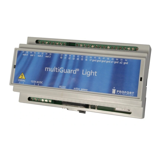
multiGuard® Light
Remote control and alarm via GSM
INDHOLD
1. SYSTEM DESCRIPTION ...................................................2
2. MOUNTING ...................................................................3
Prepare the central unit..................................................3
Install SIM-card ..............................................................3
Electric mounting ...........................................................3
DIP switches for analog inputs .......................................4
Without SIM-card ...........................................................4
3. PREPARE PC ..................................................................5
3.1 Connect PC...............................................................5
3.2 Set-up via USB-RS232 serial converter .....................5
3.3 Find Com-number.....................................................5
4. INSTALLATION OF PC-PROGRAM ..................................6
Window 1: Modem.........................................................8
Window 2: Receiver(s)....................................................9
Window 3: Inputs .........................................................10
6. SETTING UP WITH SMS................................................16
Shift PIN-code ..............................................................16
Lost password ..............................................................16
Deactivate password ....................................................16
Setting up receiver(s)....................................................16
Delete receiver .............................................................17
Setting up zone for receiver..........................................17
Approve telephone numbers ........................................17
Change the priority of receivers ...................................17
6.1 SETTING UP DIGITAL INPUTS .....................................18
Set up text....................................................................18
Delete text....................................................................18
Send alarm only if text is entered.................................18
Set up zone for digital input .........................................18
Use input 0 for connection/disconnection ....................18
Set up delayed connection/disconnection.....................18
Set up filter on input ....................................................18
Use input 1 for counting pulses....................................19
Set up different voice message for close open .............19
Delete different voice message for close open .............19
Set up delay on voice message/DTMF ..........................19
Activate 24V.................................................................19
Deactivate 24V.............................................................19
Activate command in text field ....................................19
6.2 SET UP ANALOG INPUTS ...........................................19
Profort A/S • Gunnar Clausens Vej 3 DK 8260 Viby J • Tel. +45 70233600 Fax +45 70233601 • E-mail: info@profort.com www.profort.dk
Manual
Set up zone for analog input ....................................... 20
6.3 SETTING UP OUTPUTS ............................................... 20
Activate output in case of alarm.................................. 20
Output follows input ................................................... 20
No activation of outputs.............................................. 21
Outputs show connection/disconnection ..................... 21
Delete outputs show connection/disconnection .......... 21
Combine alarm and connection/disconnection ............ 21
Set up macro ............................................................... 21
Delete macro ............................................................... 22
6.4 SYSTEM MESSAGES AND ALARMS ............................ 22
Send message on connection/disconnection................ 22
Return command ......................................................... 22
Deactivate return command ........................................ 22
disconnected ............................................................... 22
Send alarm immediately on power failure ................... 22
Send status message ................................................... 22
Deactivate send status message.................................. 22
Set time in the unit ...................................................... 22
Delete time in the unit................................................. 23
connection/disconnection of the unit........................... 23
connection/disconnection of the unit........................... 23
Text to and from serial port (RS232)............................ 23
Receive text from PLC.................................................. 23
Send text to PLC .......................................................... 23
Data communication with PLC .................................... 23
6.5 COMMANDS FOR SET-UP .......................................... 24
7. RECORDING MESSAGES .............................................. 30
Duration of voice messages......................................... 30
8. OPERATING................................................................. 31
Connect/disconnect the unit ........................................ 31
Control relay-outputs................................................... 31
Interrupt further alarms ............................................... 31
Requests to the unit .................................................... 32
Activate macros........................................................... 32
Activate macro by call and DTMF: ............................... 32
Restore default settings............................................... 32
9. FREQUENTLY ASKED QUESTIONS ................................ 33
10. SPECIFICATIONS........................................................ 36
Ver. 2.02
Advertisement
Table of Contents

Related Manuals for MULTIGUARD Light

Summary of Contents for MULTIGUARD Light
-
Page 1: Table Of Contents
Light Manual Remote control and alarm via GSM Ver. 2.02 Set up zone for analog input ........20 INDHOLD 6.3 SETTING UP OUTPUTS ..........20 1. SYSTEM DESCRIPTION ...........2 Activate output in case of alarm........20 2. MOUNTING ..............3 Output follows input ........... -
Page 2: System Description
Light Mounting Remote control and alarm via GSM Ver. 2.02 1. S YSTEM DESCRIPTION Automatic alarm in case of sabotage and power The unit is used for controlling relays and failure (also in disconnected state). data/alarm- transmission via the GSM-network. -
Page 3: Mounting
Light Mounting Remote control and alarm via GSM Ver. 2.02 9. Send, if necessary, a SMS with ”1234 2. M OUNTING OK” to get the GSM signal strength. It The unit has a built-in GSM-modem. All types of must be higher than 25%. -
Page 4: Dip Switches For Analog Inputs
Light Mounting Remote control and alarm via GSM Ver. 2.02 5. Connect analog inputs: As default the analog inputs function as ordinary digital inputs (all Dip - switches off). If the analog inputs are to be adapted to standard equipment:... -
Page 5: Prepare Pc
Light Prepare PC Remote control and alarm via GSM Ver. 2.02 Install the driver enclosed with the USB- 3. P REPARE converter and follow the instructions for Start by connecting the serial converter and this product. finding the COM-port number on the PC. -
Page 6: Installation Of Pc-Program
Light Prepare PC Remote control and alarm via GSM Ver. 2.02 Read the USB-to-Serial COM-Port. 4. I NSTALLATION OF PROGRAM When the COM-no. is identified start the PC- program for setting up the unit. Install the set-up program on the PC: 1. - Page 7 COM-port is selected, the unit is turned off or the RS232 cable is defect. If the text ’Connection to multiGuard’ doesn’t appear, you have to check if the correct COM-port has been selected. 7. Click the ‘Back’ button. Select Communication port, only available communications ports are listed.
-
Page 8: Setting Up With "Quick-Setup
Light Setting up with Remote control and alarm via GSM Quick set-up Ver. 2.02 5. S ”Q ” ETTING UP WITH UICK SETUP Start Quick set-up on the PC and follow the set-up instructions through the 4 windows. The settings will be stored in unit’s ’flash memory’... -
Page 9: Window 2: Receiver(S)
Light Setting up with Remote control and alarm via GSM Quick set-up Ver. 2.02 Window 2: Receiver(s) It is possible to encode max. 25 receivers/ telephone numbers. Forward alarms Alarm messages can be forwarded as SMS, Voice, DTMF or E-mail. If you wish to receive both a SMS and an analog voice message it is necessary to set up the same telephone number twice. -
Page 10: Window 3: Inputs
Light Setting up with Remote control and alarm via GSM Quick set-up Ver. 2.02 Window 3: Inputs if the unit is not to be set up with user defined texts the unit will send the following standard messages in case of alarm: •... - Page 11 Light Setting up with Remote control and alarm via GSM Quick set-up Ver. 2.02 Zone ”Zone” is optional and can be used for locating alarms in categories, e.g. some alarms in zone 1 and other alarms in zone 2.
- Page 12 Light Setting up with Remote control and alarm via GSM Quick set-up Ver. 2.02 ‘Send different voice messages’: If the option is selected, a voice message for open input and another voice message for closed input can be sent. If empty the voice message is the same for open and closed state.
- Page 13 Light Setting up with Remote control and alarm via GSM Quick set-up Ver. 2.02 If the same person is to receive both a SMS and a voice call the same phone number must be entered twice in the call list, e.g. in a way that Peter has position 1+2 (+4511111111), Bob position 3+4 (+4522222222) and John position 5-6 (+4533333333).
- Page 14 Light Setting up with Remote control and alarm via GSM Quick set-up Ver. 2.02 Window 4: Output Setting up outputs ’Activate relay outputs on alarms’: Indicates if output must activate (close) in case of alarm and for how long. 10 sec., 20 sec., 40 sec., 1 min., 2 min., 4 min., 8 min., 15 min., Infinitely, Reflect inputs.
- Page 15 Light Setting up with Remote control and alarm via GSM Quick set-up Ver. 2.02 the unit sends the same power alarm as before after 30 min. and then shuts down. When the power returns the unit sends the standard text ‘Power Ok’.
-
Page 16: Setting Up With Sms
Light Setting up with SMS Remote control and alarm via GSM - PIN-code, password & receivers - Ver. 2.02 activated it is necessary to encode own 6. S ETTING UP WITH telephone number. Otherwise the information is The unit can be set up with SMS from a GSM- not applied. -
Page 17: Delete Receiver
Light Setting up with SMS Remote control and alarm via GSM - PIN-code, password & receivers - Ver. 2.02 Example: send one SMS at the start of the week e.g. ‘1234 NR 123’. 1234 N4 200 aaaa@bb.dk Sets up receiver nr. 4: e-mail (200= Telephone 1234 RN nnn…(n=0..9 , A..P). -
Page 18: Setting Up Digital Inputs
Light Setting up with SMS Remote control and alarm via GSM - System messages & alarms - Ver. 2.02 1234 Ax Zy TEXT SETTING UP DIGITAL INPUTS Sets up text for input x (x=0..7) in zone y In stead of default texts it is possible to set up (y=0..7) on open/break. -
Page 19: Use Input 1 For Counting Pulses
Light Setting up with SMS Remote control and alarm via GSM - System messages & alarms - Ver. 2.02 Activate 24V 1234 Lx Xy TEXT Sets up text on input x (x=0..7) on ’close/make’ 1234 WN with a filter in zone y (y=0..7). -
Page 20: Set Up Zone For Analog Input
Light Setting up with SMS Remote control and alarm via GSM - System messages & alarms - Ver. 2.02 Ok text: Message when measuring goes 6.3 S ETTING UP OUTPUTS from alarm interval to normal interval. Relay-outputs can be activated when the inputs changes their position. -
Page 21: No Activation Of Outputs
Light Setting up with SMS Remote control and alarm via GSM - System messages & alarms - Ver. 2.02 Set up macro By a macro it is possible to gather one or more commands in a ”super command” named after your own choice. -
Page 22: Delete Macro
Light Setting up with SMS Remote control and alarm via GSM - System messages & alarms - Ver. 2.02 Commands start with < and ends with > Send sabotage and power alarm when ,e.g.: <S3;TP T 0001> (close the unit is disconnected... -
Page 23: Delete Time In The Unit
Light Setting up with SMS Remote control and alarm via GSM - System messages & alarms - Ver. 2.02 sending of status messages. There are 2 ways to a text sequence ”TRANSFER THIS TEXT” which set the time: ends with CR+LF will be transferred with 9600 baud to e.g. -
Page 24: Commands For Set-Up
Light Code summary Remote control and alarm via GSM - Commands for set-up- Ver. 2.02 6.5 C OMMANDS FOR SET setting up The code summary below joins all commands used for the unit. These commands feeds the unit with information about what to do in case of alarm on an input, for instance who is supposed to receive the alarm. - Page 25 Light Code summary Remote control and alarm via GSM - Commands for set-up- Ver. 2.02 up to NP. Set up receiver in a zone: Sets up receiver 2 for zone 1 = 12. 1234 12 +4577777777 Sets up receiver 3 for zone 1 = 13.
- Page 26 Light Code summary Remote control and alarm via GSM - Commands for set-up- Ver. 2.02 sabotage on the unit (max. 64 characters). The 1234 L9 TEXT default text is ’SABOTAGE’. Zone on input: When coding the text for inputs it is possible to...
- Page 27 Light Code summary Remote control and alarm via GSM - Commands for set-up- Ver. 2.02 V and for 0-20 mA. Example: FFFF (min.) is the 1234 V1 S FFFF TTTT value for 0 V, and TTTT (max.) is the value for 10 V.
- Page 28 Light Code summary Remote control and alarm via GSM - Commands for set-up- Ver. 2.02 closed by activating with the command S0, S1, S2 etc. If there is no use of zones or… if alarm is connected to zone 0, relay 0 will be activated.
- Page 29 Light Code summary Remote control and alarm via GSM - Commands for set-up- Ver. 2.02 Status: Defines when the unit is to send a status message several times daily: KKKK indicates the number of 1234 TP T KKKK 15 min. between each status message. Example: 0004 = each hour.
-
Page 30: Recording Messages
Light Recording messages Remote control and alarm via GSM Ver. 2.02 7. R Duration of voice messages ECORDING MESSAGES The unit has a capacity of 90 sec. voice memory Sec. and will always start by playing the general #8 General message message (8 sec.) followed by the actual alarm... -
Page 31: Operating
Light Operating Remote control and alarm via GSM - Connection/disconnection, controlling, requests, default settings- Ver. 2.02 1234 GA where output reflects input 8. O PERATING (relays will follow input 0-3). Operating covers the following: Control relay-outputs with SMS Connection/disconnection of the unit Closes output x. -
Page 32: Requests To The Unit
Light Operating Remote control and alarm via GSM - Connection/disconnection, controlling, requests, default settings- Ver. 2.02 Returns all texts of inputs in Requests to the unit 1234 PR T the unit. (digital/analog). Requests will be returned to the mobile which Incl. -
Page 33: Frequently Asked Questions
Light Frequently Asked Questions Remote control and alarm via GSM Ver. 2.02 9. F REQUENTLY ASKED QUESTIONS Error description Cause Solution At start up the central unit ’beeps’ Wrong PIN-code for the SIM-card: Set the PIN-code of the SIM-card rapidly…... - Page 34 Light Frequently Asked Questions Remote control and alarm via GSM Ver. 2.02 input 0… connection of the central unit, then use the command ”RP” if input 0 is activated with a pulse. If input 0 is activated with a level, then use ”RN”.
- Page 35 Light Frequently Asked Questions Remote control and alarm via GSM Ver. 2.02...
-
Page 36: Specifications
Light Specifications Remote control and alarm via GSM Ver. 2.02 10. S PECIFICATIONS Power supply: Built in: 230V AC External: 12-24V AC/DC min 0,5 A Consumption: Approx. 30 mA in standby (powered by 12 V) Outputs: Max. 6 A by 230 V AC Max.
Need help?
Do you have a question about the Light and is the answer not in the manual?
Questions and answers