Advertisement
Quick Links
GDZW7-ECO Z-Wave®
Long Range Garage Door Controller
Installation Instructions and User Manual
(Scan QR Code for online content.)
•
Specifications
Operating Frequency:
Z-Wave Long Range (912MHz, 920MHz),
Z-Wave (908.42MHz, 916MHz),
310MHz, 315MHz, 345MHz, 390MHz
Operating Temperature:
-4° – 140°F (-20° – 60°C)
Power:
12VDC, 1.0A
•
Package Contents
1x Garage Door Controller
1x Tilt Sensor (color may vary)
1x AC/DC Power Adapter
1x 2-Sided Adhesive Tape (Tilt Sensor)
1x Mounting Bracket
2x Mounting Screws
4x Screws, Washers, Wall Anchors 1x Quick Start Guide
2x Hex Bolts, Flat Washers, Split Lock Washers, Nuts
1x Back Side Mounting 2-Sided Adhesive Tape
•
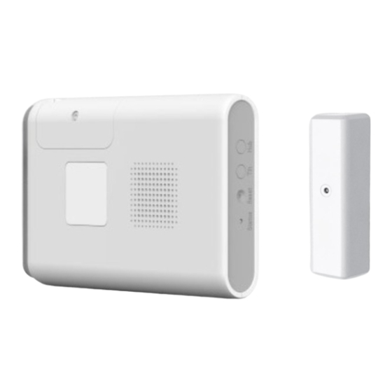
Component Identification
GARAGE DOOR CONTROLLER
power adapter, mounting bracket, tape, and hardware
AC/DC Power
High-Power
Adapter
LED
Warning Light
Audio
Warning
Beeper
•
Buttons, Wiring and Status LED:
• Typical Installation
The Garage Door Controller is pre-paired with a
wireless tilt sensor. The Garage Door Controller
may ignore commands to control the garage
door if it deems that it is unsafe to execute the
command.
INSTALLATION OUTLINE:
1. Add Garage Door Controller to a Z-Wave® Network Hub
2. Mount and activate the Tilt Sensor
3. Mount and connect the Garage Door Controller
4. Test system operation
Caution: For safety always temporarily disconnect power from the garage door opener when
working near the moving parts.
Step 1: Adding to a Z-Wave® Network
Power up the GDZW7-ECO with the included AC/DC power adapter, and the device's status
indicator will blink green twice per second to indicate that the GDZW7-ECO is actively looking
to be included into a network.
The GDZW7-ECO must not already be added to a Z-Wave network. If the device was
previously added to another Z-Wave network, follow the advanced instructions on removing
it from the previous network.
There are a few methods to add a device to a Z-Wave network: SmartStart, Classic and
Network Wide Inclusion.
For both methods, you may need to locate the Device Specific Key (DSK) which is on the
device's box and on the back side of the device itself. Scan the DSK QR-Code with the
panel's or controller's smartphone app or enter it in manually when prompted.
Note: Adding in the device as a long-range node can only be done via SmartStart.
TILT SENSOR
mounting screws (2) and tape
SmartStart:
1. When the GDZW7-ECO is powered up and not included in a network, with the status
indicator blinking green twice per second, it is ready for SmartStart.
2. The device may take a few minutes to be added, blinking green rapidly while adding.
3. When it is successfully added, the device will beep and status indicator will
illuminate green.
Classic / Network-Wide Inclusion
1. Follow the instructions of the Z-Wave controller to put the Z-Wave controller into
manual or classic Z-Wave inclusion mode.
2. Locate and press the "Hub" button on the device.
3. The device will attempt to include itself, with status indicator blinking green rapidly.
4. Be prepared to enter the DSK if asked.
5.
When it is successfully added, the device will beep and status indicator will
illuminate green.
If the device beeps twice and illuminates yellow 3 seconds, then it was added unsecured, and
the device will automatically factory reset itself. This may leave a ghost node on the Z-Wave
controller. Follow the Z-Wave controller's instructions to remove the unresponsive node. If the
status indicator illuminates red for three seconds the device was NOT added to the network.
This device also supports Network Wide Inclusion such that the device can be included into the
DC Power Input
Z-Wave network over the mesh network and not directly near the main controller. This mode
is automatically activated after regular inclusion was not successful.
Once the GDZW7-ECO is successfully added to the Z-Wave network, the tilt sensor and the
GDZW7-ECO can be mounted.
Step 2: Mount the Tilt Sensor
Door Opener Relay
External Contact Switch or
Switch Wiring Points
Sensor Wiring Points (BLUE)
(GREEN) and Wire Lead
Optional feature
Activate Tilt Sensor
(included)
First, activate the tilt sensor by pulling the battery tab from the
Tilt Sensor (or re-installing the battery).
Identify Location for Tilt Sensor:
Choose a mounting method that is appropriate for your
garage door. It is very important that the Tilt sensor be
located on the top section of a multi-panel garage door.
This will be the first section to tilt when the door is
opened and the last to move to the vertical position
when closing.
Mount the Tilt Sensor to a clean dry surface WITH THE
ARROW ON THE SIDE OF THE SENSOR POINTING UP.
The sensor can be mounted using adhesive tape and/or
screws.
Caution: Use of the screws is only recommended for garage doors that are thicker than the
screws are long. Use only the adhesive tape to mount the tilt sensor for any garage door that
is thinner than the length of the provided screws (including many modern metal garage
doors).
Step 3: Hard Mount the GDZW7-ECO (Preferred)
Identify Location:
This is the preferred method, if the opener's mounting hardware is sturdy, secure, and there
is sufficient space to safely install
the GDZW7-ECO. Whenever
possible align the front side of the
GDZW7-ECO so it generally faces
the Hub or Panel with which it is
paired.
Using the included mounting bracket and two sets of hex head bolts, flat washers, split lock
washers and nuts, affix the bracket to the garage door opener's mounting hardware. Then
align the slots on the back of the GDZW7-ECO with the bracket, and slide until it snaps in
place for a secure hold.
Ceiling Mount the GDZW7-ECO (Option 2)
Identify Location:
The GDZW7-ECO placement should be on the ceiling within 6
inches from the points where the garage door opener is
mounted to the ceiling, so opener operation can be detected.
Mount the GDZW7-ECO on the ceiling near the garage door
opener and the power outlet using the included mounting
bracket and four sets of screws, washers, and plastic anchors.
Advertisement

Related Manuals for Ecolink Z-Wave GDZW7-ECO

Summary of Contents for Ecolink Z-Wave GDZW7-ECO
- Page 1 • Buttons, Wiring and Status LED: This device also supports Network Wide Inclusion such that the device can be included into the DC Power Input Z-Wave network over the mesh network and not directly near the main controller. This mode GDZW7-ECO Z-Wave®...
- Page 2 External Contact Switch or Alternatively, the GDZW7-ECO can pair with an Ecolink Intelligent Technology Inc. warrants that for a period of 1 year from the date of purchase that this product is free Sensor Wiring Points (BLUE) Caution: Be sure the GDZW7-ECO and its wires are clear of all moving parts, and the external contact to monitor the state of the garage from defects in material and workmanship.
Need help?
Do you have a question about the Z-Wave GDZW7-ECO and is the answer not in the manual?
Questions and answers