
Subscribe to Our Youtube Channel
Related Manuals for AVT Prosilica GS Series


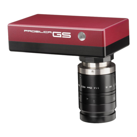
Summary of Contents for AVT Prosilica GS Series
- Page 1 AVT Prosilica GS Technical Manual AVT GigE Vision Cameras V2.0.0 70-0066 14 July 2011 Allied Vision Technologies Canada Inc. 101-3750 North Fraser Way V5J 5E9, Burnaby, BC / Canada...
- Page 2 It is not permitted to copy or modify them for trade use or transfer, nor may they be used on web sites. Allied Vision Technologies Canada Inc. 7/2011 All rights reserved. Managing Director: Mr. Frank Grube TaxID: 889528709 Headquarters: 101-3750 North Fraser Way V5J 5E9, Burnaby, BC / Canada AVT Prosilica GS Technical Manual V2.0.0...
-
Page 3: Table Of Contents
Camera I/O opto-isolated user circuit example ............... 31 Camera I/O non-isolated user circuit example ..............32 Video iris user circuit example ..................33 Notes on triggering ....................34 Timing diagram ......................34 Signal definitions ..................... 35 AVT Prosilica GS Technical Manual V2.0.0... - Page 4 Prosilica GS family frame rate comparison ..............40 Additional References ..................... 41 Prosilica GS webpage....................41 Prosilica GS documentation ..................41 GigE PvAPI SDK ......................41 Knowledge base ....................... 41 Case studies ......................41 Prosilica GS firmware ....................41 AVT Prosilica GS Technical Manual V2.0.0...
-
Page 5: Contacting Allied Vision Technologies
101-3750 North Fraser Way Burnaby, BC, V5J 5E9, Canada Tel: +1 604-875-8855 Fax: +1 604-875-8856 e-mail: info@alliedvisiontec.com Allied Vision Technologies Asia Pte. Ltd. 82 Playfair Road #07-02 D'Lithium Singapore 368001 Tel. +65 6634-9027 Fax:+65 6634-9029 e-mail: info@alliedvisiontec.com AVT Prosilica GS Technical Manual V2.0.0... -
Page 6: Introduction
Prosilic ca GX, GE, GS, GB and GC refer r to the AVT P Prosilica Gig gE Camera an nd Driver At ttributes doc cument. VT Prosilica G S literature: tp://www.al... -
Page 7: Symbols Used In This Manual
Canada prov vides a 2-yea ar warranty w which vers the repl lacement and d repair of al ll AVT parts t that are foun nd to be fective in the e normal use e of this prod duct. AVT wil... -
Page 8: Precautions
AVT Pro osilica GS Tec chnical Manu ual V2.0.0... -
Page 9: Cleaning The Sensor
Rep eat this process until the debris s is gone. If thi is process fails to remove the debris, then co ontact AVT. AVT Pro osilica GS Tec chnical Manu ual V2.0.0... -
Page 10: Conformity
Conformity Allied Vision Technologies declares under its sole responsibility that all standard cameras of the AVT Prosilica GS family to which this declaration relates are in conformity with the following standard(s) or other normative document(s): • CE, following the provisions of 2004/108/EG directive •... -
Page 11: Specifications
10ns for non-isolated I/O, 1.3μs for isolated I/O Operating humidity 20 to 80% non-condensing Hardware interface standard IEEE 802.3 1000BASE-T, 100BASE-TX Software interface standard GigE Vision Standard 1.0 Regulatory CE, FCC Class A, RoHS (2002/95/EC) Table 2: Prosilica GS650 camera specification AVT Prosilica GS Technical Manual V2.0.0... - Page 12 Wavelength [n Figure e 2 – Prosilica a GS650C col lor spectral r response e design and d specificatio ons for the pr roducts desc cribed above ange withou t notice. AVT Pro osilica GS Tec chnical Manu ual V2.0.0...
-
Page 13: Prosilica Gs660/660C
10ns for non-isolated I/O, 1.3μs for isolated I/O Operating humidity 20 to 80% non-condensing Hardware interface standard IEEE 802.3 1000BASE-T, 100BASE-TX Software interface standard GigE Vision Standard 1.0 Regulatory CE, FCC Class A, RoHS (2002/95/EC) Table 3: Prosilica GS660 camera specification AVT Prosilica GS Technical Manual V2.0.0... - Page 14 Wavelength [ [nm] Figure 4 – – Prosilica GS S660C color spectral resp ponse e design and d specificatio ons for the pr roducts desc cribed above ange withou t notice. AVT Pro osilica GS Tec chnical Manu ual V2.0.0...
-
Page 15: Prosilica Gs1380/1380C
10ns for non-isolated I/O, 1.3μs for isolated I/O Operating humidity 20 to 80% non-condensing Hardware interface standard IEEE 802.3 1000BASE-T, 100BASE-TX Software interface standard GigE Vision Standard 1.0 Regulatory CE, FCC Class A, RoHS (2002/95/EC) Table 4: Prosilica GS1380 camera specification AVT Prosilica GS Technical Manual V2.0.0... - Page 16 Wavelength [nm] Figure 6 – – Prosilica GS S1380C color r spectral res sponse e design and d specificatio ons for the pr roducts desc cribed above ange withou t notice. AVT Pro osilica GS Tec chnical Manu ual V2.0.0...
-
Page 17: Prosilica Gs2450/2450C
10ns for non-isolated I/O, 1.3μs for isolated I/O Operating humidity 20 to 80% non-condensing Hardware interface standard IEEE 802.3 1000BASE-T, 100BASE-TX Software interface standard GigE Vision Standard 1.0 Regulatory CE, FCC Class A, RoHS (2002/95/EC) Table 5: Prosilica GS2450 camera specification AVT Prosilica GS Technical Manual V2.0.0... - Page 18 Wavelength [nm Figure 8 – – Prosilica GS S2450C color r spectral res sponse e design and d specificatio ons for the pr roducts desc cribed above ange withou t notice. AVT Pro osilica GS Tec chnical Manu ual V2.0.0...
-
Page 19: Camera Attribute Highlights
C Camera attr ribute e highl lights AVT cam meras suppo rt a number of standard a and extende ed features. T The table be elow identifi ies the most interesting c capabilities of this came ra family. A complete lis... -
Page 20: Ir Cut Filter: Spectral Transmission
IRC filter mily from Sun nex. Prosilic ca GS camera as utilize the e IRC30 filter Figure 9: Sun nex IRC filter r transmissio on values AVT Pro osilica GS Tec chnical Manu ual V2.0.0... -
Page 21: Camera Dimensions
GS1380 orientatio ble 7: GS Sen nsor orientat tions me models d do not suppo ort a portrait sensor orien ntation, plea ase refer Chapter Spe ecifications o on page 11. AVT Pro osilica GS Tec chnical Manu ual V2.0.0... -
Page 22: Mechanical Drawings - Landscape Sensor
1.00 25.4 ITEM 2: HALO HFJ11-1G16E-L12RL ITEM 3: SONY ICX424 1.50 38 INCHES[MILLIMETERS] *Nominal for C mount. Reduce by 5mm for CS mount. Add 0.3mm for color option. Figure 10: Prosilica GS650/GS650C mechanical drawing AVT Prosilica GS Technical Manual V2.0.0... -
Page 23: Portrait Sensor
ITEM 1: 3M 10214-55G3PC 1.00 25.4 ITEM 2: HALO HFJ11-1G16E-L12RL ITEM 3: SONY ICX424 1.50 INCHES[MILLIMETERS] *Nominal for C mount. Reduce by 5mm for CS mount. Add 0.3mm for color option. Figure 11: Prosilica GS650-P/GS650C-P mechanical drawing AVT Prosilica GS Technical Manual V2.0.0... -
Page 24: Adjustment Of Lens Mount
AVT N: 02-5003A osilica GS cam meras can be e equipped w with a C-mou nt or a CS-m ount... -
Page 25: Camera Interfaces
/products/a accessories/g gige- cessories.htm Figure 1 3: Prosilica G GS connectio on diagram AVT Pro osilica GS Tec chnical Manu ual V2.0.0... -
Page 26: Camera I/O Connector Pin Assignment
3M 1031 4-3210-00X (X indicates s color prefer rence). is cable side Hirose conn nector can be e purchased f from AVT. VT P/N: 02-70 003A AVT Pro osilica GS Tec chnical Manu ual V2.0.0... - Page 27 : 02-22XXB, 5V - 25V. 12 2V Nominal. 12V power ad daptor with c camera conn ector can be e ordered fro m AVT: VT P/N: 02-80 007A North A America Supp VT P/N: 02-80 008A Univers sal Supply Camer...
- Page 28 GPOut2 is to be used or if the RS-232 port is to be used. Note that non-isolated Ground is common with External (power) Ground however it is good practice to provide a separate ground connection for power and signaling when designing the cabling. AVT Prosilica GS Technical Manual V2.0.0...
-
Page 29: Gigabit Ethernet Port
Ethernet sta andard (IEEE E 802.3 1000 0BASE-T). • Cables with screw-lock c connectors a are available from AVT: http://www w.alliedvision ntec.com/em mea/products s/accessorie es/gige- accessories. .html AVT Pro osilica GS Tec chnical Manu... -
Page 30: Camera I/O Internal Circuit Diagram
Used to drive the RS232 signal Used to drive the non-isolated trigger coupled to two GaAs infrared LEDs. This is the logic via the external connector signals from the camera. input and output of the opto isolated camera trigger AVT Prosilica GS Technical Manual 2.0.0... -
Page 31: Camera I/O Opto-Isolated User Circuit Example
Fairchild MO OCD207. The cor rresponding tran nsistor emitter is s connected to olated ground. S See the Fairchild d MOCD207 data sheet for more d detailed informa ation. AVT Pros ilica GS Technica al Manual 2.0.0... -
Page 32: Camera I/O Non-Isolated User Circuit Example
Texas Instrumen nts SN74LVC2G2 241 buffer/drive er inside the cam mera. See the exas Instruments s SN74LVC2G241 1 for more detai led information. AVT Pros ilica GS Technica al Manual 2.0.0... -
Page 33: Video Iris User Circuit Example
It allows the user to manually control the exp osure and gain v values and rely s solely on the aut to iris for adjust tment to mbient lighting AVT Pros ilica GS Technica al Manual 2.0.0... -
Page 34: Notes On Triggering
Notes on triggering Timing diagram Figure 18: Prosilica GS internal signal timing waveforms AVT Prosilica GS Technical Manual 2.0.0... -
Page 35: Signal Definitions
... is high when the camera image sensor is either exposing and/or reading out data. Idle ... is high if the camera image sensor is not exposing and/or reading out data. Table 9: Explanation of signals in timing diagram AVT Prosilica GS Technical Manual V2.0.0... - Page 36 Trigge r Latency an d Trigger Jitt ter can be up p to 1 line tim me since Exp posure must al lways begin o on an Interli ine boundary AVT Pro osilica GS Tec chnical Manu ual V2.0.0...
- Page 37 Sample View wer or ird party app plications like e NI’s Measu urement and Acquisition sistant. Figure 1 19: Screensh ot of AVT Gig gE Sample Vi iewer contro ls window AVT Pro osilica GS Tec chnical Manu ual V2.0.0...
- Page 38 Mono8 or Bayer8 CAMER RA: Pros silica GS S650 Height pixels) 1000 Frame rate gure 20: Maxi imum frame rate versus r region heigh t for GS650 AVT Pro osilica GS Tec chnical Manu ual V2.0.0...
- Page 39 CAMERA: Prosilica GS660 Height (pixels) Frame rate Figure 21: Maximum frame rate versus region height for GS660 CAMERA: Prosilica GS1380 1200 1000 Height (pixels) Frame rate Figure 22: Maximum frame rate versus region height for GS1380 AVT Prosilica GS Technical Manual V2.0.0...
- Page 40 Figure 23: Maximum frame rate versus region height for GS2450 Prosilica GS family frame rate comparison 2500 2000 1500 GS650 Height (pixels) GS660 1000 GS1380 GS2450 1010 Frame rate Figure 24: Maximum frame rate versus region height for all GS cameras AVT Prosilica GS Technical Manual V2.0.0...
- Page 41 Additional References Prosilica GS webpage http://www.alliedvisiontec.com/us/products/cameras/gigabit-ethernet/prosilica-GS.html Prosilica GS documentation http://www.alliedvisiontec.com/us/support/downloads/product-literature/prosilica-GS.html GigE PvAPI SDK http://www.alliedvisiontec.com/us/products/software/avt-pvapi-sdk.html Knowledge base http://www.alliedvisiontec.com/us/support/knowledge-base.html Case studies http://www.alliedvisiontec.com/us/products/applications.html Prosilica GS firmware http://www.alliedvisiontec.com/us/support/downloads/firmware.html AVT Prosilica GS Technical Manual V2.0.0...
Need help?
Do you have a question about the Prosilica GS Series and is the answer not in the manual?
Questions and answers