Advertisement
Quick Links
Advertisement

Related Manuals for THK PPR


Summary of Contents for THK PPR
- Page 1 Pick and Place Robot INSTRUCTION MANUAL Smart Logo...
- Page 2 Problems Do you have these kinds of problems at your worksite? Support is needed to improve quality and productivity. I want to reduce workpiece damage Problem I want to reduce workpiece damage and aim for zero defects! Workpieces have gotten progressively more delicate, so it is difficult to improve production speed without causing damage.
- Page 3 Solutions Pick and Place Robot provides the best solutions to worksite problems. The PPR solves a variety of issues, such as stabilizing quality and reducing cycle time. Reduces workpiece damage Solution Uses load control with high-resolution force sensors to quickly stop the moment the suction nozzle contacts the workpiece.
- Page 4 Contents 1. Introduction Acknowledgment― ―――――――――――――――――――――――――――― 1 About this manual― ―――――――――――――――――――――――――――― 1 How to use this product― ――――――――――――――――――――――――― 2 About product support― ―――――――――――――――――――――――――― 2 2. Safety precautions About ranks of precautions― ―――――――――――――――――――――――― 3 About descriptions of precautions― ――――――――――――――――――――― 3 Safety precautions――――――――――――――――――――――――――――― 4 3.
- Page 5 Contents 5-2-2 Wiring the head cables― ――――――――――――――――――――― 33 5-2-3 USB connection (PC connection)― ― ―――――――――――――――― 34 5-2-4 LAN connection (PLC connection)― ―――――――――――――――― 34 Pneumatic system piping――――――――――――――――――――――――― 35 5-3-1 Handling method for tubes― ――――――――――――――――――― 35 5-3-2 Mounting nozzles― ――――――――――――――――――――――― 36 6. PC application program settings ―...
- Page 6 Contents 6-5-2 ― Advanced―settings―for―Z―axis/θ―axis―parameters― ―――――――――― 103 6-5-3 Understanding gain adjustment― ――――――――――――――――― 106 Event history function― ――――――――――――――――――――――――― 108 6-6-1 Viewing event history――――――――――――――――――――――― 108 6-6-2 Event code list―――――――――――――――――――――――――― 109 6-6-3 Acquire present waveform data― ――――――――――――――――― 110 6-6-4 Status display― ――――――――――――――――――――――――― 110 6-6-5 Initializing event history――――――――――――――――――――――...
- Page 7 Contents 9-2-1 ― Replacing―the―pneumatic―filter― ―――――――――――――――――― 154 9-2-2 Replacing the pneumatic module―――――――――――――――――― 155 Product warranty― ――――――――――――――――――――――――――― 156 9-3-1 Free warranty period― ―――――――――――――――――――――― 156 9-3-2 Usage conditions (range)― ―――――――――――――――――――― 156 9-3-3 Warranty scope― ―――――――――――――――――――――――― 156 9-3-4 ― Exclusion―of―warranty―liability― ―――――――――――――――――― 158 9-3-5 Delivery conditions―――――――――――――――――――――――― 158 10.
- Page 8 Introduction Acknowledgment Thank you for purchasing the PPR Pick and Place Robot. This product is a robot optimized for pick and place applications that supports linear and rotary operation and also has pneumatic equipment and various sensors built-in. This is a new product that achieves a reduction in workpiece damage and a shortened cycle time, which are two important goals for production sites for electronic components and so forth.
- Page 9 About product support ▶ Product and company information We recommend that you periodically check the THK website for the latest product and company information. Website URL: http://www.thk.com/...
- Page 10 Safety precautions Before performing the installation and wiring for this product, carefully read the safety precautions. Always―observe―the―precautions―in―"2-3―Safety―precautions."―Specific―warnings―and―precautions― are listed in the relevant parts of this manual. About ranks of precautions This―manual―classifies―safety―precautions―into―three―ranks:―"Danger,"―"Warning,"―and―"Caution." Danger Incorrect handling has a significant possibility of causing death or serious injury Warning Incorrect handling may cause death or serious injury to a person...
- Page 11 Safety precautions Safety precautions Always observe the precautions in this section. Danger Caution Those who use a pacemaker or Do not apply impacts to the similar medical equipment must product, and be sure to avoid not come within 30 cm of the any rough handling such as product.
- Page 12 3. Product overview About this chapter This chapter introduces the overview of the PPR Pick and Place Robot for customers that will use this product. It provides information that you will need to know before you start using the product.
- Page 13 Prohibited Do not use the product if you find any abnormalities. Using a damaged product may cause malfunctions that could lead to injury or failure.―If―you―find―any―defects,―please―contact―the―PPR―sales/technical―support― center. Checking the product and accessories Upon receipt of the ordered product, immediately check the product model and product model number―and―confirm―that―the―accessories―have―been―included―before―starting―the―installation―and―...
- Page 14 Product model numbers Product Model PPR-LR3-LF1* Head PPR-LR3 (for use with position control) Controller PPR-CTR3 PPR-FXC1 PPR-FXC3 PPR-FXC5 Dedicated head cable (1 m) (3 m) (5 m) * PPR-LR3-LF1 cannot use features that require a force sensor.
- Page 15 Product overview System configuration This―section―shows―an―example―of―a―system―configuration―with―the―head―and―controller―connected― to a PC and other necessary peripheral devices. 3-3-1 System configuration example 3-3-1-1 Electrical system configuration PLC Communication type PC The peripheral devices marked with a • EtherCAT should be prepared by the customer • MECHATROLINK-III Controller as necessary. •...
- Page 16 Power supply capacity (per 1 unit) Power supply voltage Output current 24 V ± 10% 4 A or more Host device Host device (PLC) The PPR controller supports four communication types: EtherCAT, MECHATROLINK-III, EtherNet/IP, and Ethernet (TCP/IP). For―the―specifications―of―each―communication―type,―refer―to―"10-1-2―Communications― specifications." LAN cable This―differs―depending―on―the―communication―type.―Prepare―this―according―to―the―specifications―in― the table below.
- Page 17 Product overview Pneumatic devices * Be sure to prepare pneumatic devices for air cooling, suction, and clean rooms in separate systems. * For details about handling pneumatic devices, refer to the instruction manuals for each product. For air cooling When using devices in a stacked installation or high-load operations, the internal temperature will rise.
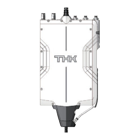
- Page 18 Product overview Names and functions of each part 3-4-1 Head (1) Power/communication connector (2) Fitting for air cooling (OUT) (3) Fitting for suction air (positive pressure) (2) Fitting for air cooling (IN) (3) Fitting for suction air (negative pressure) (4) Fitting for clean rooms (5) Status display (6) Front cover (7) Filter replacement port...
- Page 19 Product overview 3-4-2 Controller (12) DIN rail mounting part (1) POWER LED (2) CONT/RUN LED (3) ERR LED (6) USB connector (4) USB LED (7) PLC communication connector (IN) (5) LINK/ACT LED (8) PLC communication connector (OUT) (9) Head connector (10) Power connector (11) Release lever Name...
- Page 20 Product overview 3-4-3 PLC network communication LED specifications Initial value Cable Pre-Op Safe-Op Operational (init) disconnect Blinking Single Flash Single Flash CONT/RUN (green) Flashing Flashing (0.2 s) Flashing (0.2 s/1 s) (0.2 s/1 s) Flickering Flickering Flickering LINK/ACT (green) EtherCAT (50 ms) (50 ms) (50 ms) Normal Incorrect settings...
- Page 21 4. Installation About this chapter This―chapter―explains―vital―information―about―installation―that―you―must―know―before―installing―the― head and controller. This chapter is primarily intended for those in charge of installation of this product to machinery and equipment. 4-1 Precautions for installation ........15 The precautions for installation are described separately for the head and the controller. Be sure to read these precautions before installing the product.
- Page 22 Installation Precautions for installation Be sure to observe the precautions below when installing the product. Precautions for installing the head Warning Do not move or mount the product while the head is energized. Otherwise, this may cause electric shocks. This may also cause malfunctions that could lead to injury.
- Page 23 Installation Precautions for installing the controller Caution Do not install the product in a high-temperature or high-humidity lo- cation, or a location where dust, metallic powder, or corrosive gases are present. Prohibited Use the controller in an ambient temperature of 50°C or less. If there are any heating elements nearby, prevent rises in temperature with a shielding cover, etc.
- Page 24 Installation Installing the head This―section―explains―the―procedure―for―installing―the―head. 4-2-1 Installation environment for the head Install the head on a level metal surface that meets the following conditions. If these conditions are―not―met,―it―may―lead―to―electric―shock―or―fire. Ambient temperature: 0°C to 40°C Ambient humidity: 20% to 80% RH (no condensation) ...
- Page 25 4-2-2 External dimensions of the head 113.5 71.5 2-ø3 2-ø3 ø3 (350) Elongated hole depth 4 2-M4 depth 4 Helisert ø4H7 depth 4 A part (15) 0.02 A ø6h7 (ø4.8) 2-M3 depth 3 M3 depth 3 A part details (S = 2 : 1) PPR―head―external―dimensions―(with―front―cover―mounted―in―standard―orientation)
- Page 26 Installation 71.5 2-ø3 2-ø3 ø3 (350) Elongated hole depth 4 2-M4 depth 4 Helisert ø4H7 depth 4 A part (15) 0.02 A ø6h7 (ø4.8) 2-M3 depth 3 M3 depth 3 A part details (S = 2 : 1) PPR―head―external―dimensions―(with―front―cover―mounted―in―reverse―orientation)
- Page 27 Installation 4-2-3 Installation standards for the head Installation location for the head Flatness―of―the―mounting―surface―for―the―head:―20―μm―(recommended―value) 4-2-4 Installation method for the head Carrying the head When―carrying―the―head,―we―recommend―holding―the―parts―circled―in―the―figure―below. The shaft part is directly connected to the sensors, so if any impacts are transmitted due to dropping,―etc.,―this―may―affect―the―operation―of―the―product.―Handle―with―care―when―transporting―...
- Page 28 Installation How to mount to installation surface Secure the head with bolts inserted from the reverse side of the installation surface. M4 bolt tightening torque (recommended): 200 N・cm/20 kgf・cm * Be careful not to tighten above the recommended tightening torque. Also, the appropriate tightening―torque―for―the―bolts―will―differ―depending―on―the―material,―type,―and―grade―of―the―...
- Page 29 Installation How to mount in a stacked installation When using devices in a stacked installation, be sure to install with the mounting directions of the head alternating. For details about dismounting and mounting the front cover and clean cover in this case, refer to―the―explanation―in―the―next―section.
- Page 30 Installation Installing the controller This―section―explains―the―procedure―for―installing―the―controller. 4-3-1 Installation environment for the controller Install the controller inside a control panel that meets the following conditions. If these conditions are―not―met,―it―may―lead―to―electric―shock―or―fire. Ambient temperature: 0°C to 50°C (no freezing) Ambient humidity: 90% RH or less (no condensation) ...
- Page 31 Installation 4-3-3 Installation standards for the controller Exterior―cables ▶ Length of each cable Do―not―exceed―the―cable―lengths―in―the―figure―below―for―the―cables―that―connect―the―PPR― controller body to each device. Also,―if―the―cables―are―long,―do―not―wrap―the―excess―cable―in―a―loop―shape.―Instead,―wrap―the― cables in a loose U shape (bending radius of 40 R). Controller body USB cable 2 m (Max.) LAN cable 30 m (Max.) Next controller Dedicated head cable 10 m (Max.)
- Page 32 Installation Installation space Multiple―units―can―be―installed―adjacently―as―in―the―figure―below―using―DIN―rails―or―brackets. However, be careful to install units such that the USB cables, LAN cables, dedicated head cables,―and―power―cables―can―still―be―plugged―in―and―unplugged―without―difficulty. Also, if there are any obstructions up, down, left, or right of the casing in the installation location, be sure to leave a gap of 30 mm or more between the obstruction and the casing. Controller body 30 mm (or more) 30 mm (or more)
- Page 33 Installation 4-3-4 Installation method for the controller ▶―When―fixing―to―a―DIN―rail If―you―plan―to―fix―the―PPR―controller―to―a―DIN―rail,―follow―the―mounting―procedure―below. Hook the upper groove onto the DIN rail. Place the lower groove so that it presses into the DIN rail. Confirm that the upper and lower grooves are firmly installed to the DIN rail.
- Page 34 Installation Mount the body with DIN rail fixing brackets to prevent movement from side to side. ▶―When―fixing―from―the―back―surface―with―bolts The―PPR―controller―can―be―directly―fixed―to―an―installation―panel―using―the―screw―holes―on―the― back surface of the controller. *―― I f―you―plan―to―fix―the―controller―with―bolts―from―the―back―surface,―be―sure―to―prepare―the―through- holes―in―advance―as―described―in―"4-3-2―External―dimensions―of―the―controller." • M4 bolt tightening torque (recommended): 140 N・cm/14.3 kgf・cm * Be careful not to tighten above the recommended tightening torque. Also, the appropriate tightening―torque―for―the―bolts―will―differ―depending―on―the―material,―type,―and―grade―of―the―bolts―...
- Page 35 Installation After―fixing―the―controller―with―bolts,―confirm―that―there―are―no―gaps―between―the―body―and―the― installation panel.
- Page 36 5. Wiring/piping About this chapter This chapter describes how to connect and perform wiring for the head, controller, and other peripheral devices, and how to handle the cables. This section describes the precautions for 5-1 Safety precautions for wiring/piping ......30 wiring and piping.
- Page 37 Wiring/piping Safety precautions for wiring/piping Be sure to observe the precautions below when doing wiring work. Warning Do not alter the included cables by extending or shortening them. Otherwise, this may cause reduced performance and malfunctions. Do not disassemble ...
- Page 38 Wiring/piping 5-1-1-1 Control panel main unit 1. Use a metallic control panel. 2. Mask joint areas such as at the top and sides of the control panel to prevent them from being coated, and weld them or tighten them with screws. 3.
- Page 39 Wiring/piping ▶ Avoid unnecessary wiring When routing the cable outside the control panel, reduce the internal wiring inside the panel as much as possible and route it from the vicinity of the opening to outside the panel. Control panel Control panel Device Device Device...
- Page 40 Wiring/piping Electrical system wiring 5-2-1 Power supply Prepare the 24 V power cable and connector according to the procedure below. * Recommended electric wire diameter: 0.5 mm (AWG20 equivalent) For the P24VP, GND, and FG cables, remove around 8 mm of the covering from the tips of the cables.
- Page 41 5-2-4 LAN connection (PLC connection) 5-2-4-1 LAN connection method This―section―explains―the―cascade―type―connection―as―an―example―of―a―LAN―connection―method. To create the host device (PLC) connection and a cascade connection for the PPR controllers, connect―the―devices―as―shown―in―the―figure―below. Connect the host device (PLC) to the IN port on the controller. When using a cascade connection, connect the OUT port of the connector to the IN port of the next―PPR―connector.
- Page 42 Wiring/piping Pneumatic system piping 5-3-1 Handling method for tubes 5-3-1-1 Mounting tubes Insert―the―tube―until―it―reaches―the―bottom―of―the―one-touch―fitting. Lightly―pull―on―the―tube―to―ensure―that―it―does―not―fall―off. 5-3-1-2 Dismounting tubes Before dismounting tubes, use a regulator or similar device that you have prepared yourself to confirm―that―the―atmospheric―pressure―inside―the―tubes―is―0. Press―down―fully―on―the―opening―(release)―ring―of―the―one-touch―fitting,―and―dismount―the―tube.
- Page 43 Wiring/piping 5-3-2 Mounting nozzles This section assumes that nozzles will be mounted using the V grooves. When mounting nozzles, ensure that the following conditions are met. The shaft dimensions are ø6, h7. If you manufacture nozzles to mount to the V grooves, be careful of the machined accuracy.
- Page 44 6. PC application program settings About this chapter This―chapter―explains―how―to―use―the―PPR―dedicated―PC―application―"T-ACT"―as―well―as―the― operational functions that can be achieved with the PPR. This―section―explains―the―environment― 6-1― Application―environment―configuration ....38 configuration―for―the―application,―including― the PC environment, installation, and the language settings. 6-2― Confirmation―of―head―operations ......48 This―section―describes―how―to―confirm―the― operation and perform adjustments for a head using T-ACT.
- Page 45 Application environment configuration Understanding the PPR operation program Projects The PPR manages operation programs in units called projects. 32 sequences can be saved in a project. Project Sequence Part 1 Pickup Sequence Part 1 Place ·...
- Page 46 6-1-2 Installation procedure Follow the procedure below in order to install the THK_T-ACT (hereafter abbreviated as T-ACT). For information about where to acquire T-ACT, contact the PPR sales/technology support center. Unzip the installer (THK_T-ACT_Installer.zip), and double-click the "setup.exe" file inside the extracted folder.
- Page 47 Trial run/ Event Sequence Tuning PC application program settings environment of head Monitor history program function configuration operations functions function Enter a shortcut name for the program, and click "Next >." * ― I f―nothing―is―specified,―the―shortcut―will―be―named―"THK." Click "Install." The installation will start.
- Page 48 Application Confirmation Trial run/ Event Sequence Tuning PC application program settings environment of head Monitor history program function configuration operations functions function Click "Finish." You―have―now―completed―the―installation―process.―If―the―check―box―is―checked,―T-ACT―will― start up. 6-1-3 Uninstallation procedure Follow the procedure below in order to uninstall T-ACT. Open Windows "Settings" and click on "Apps & features." Select "THK_T-ACT,"...
- Page 49 Monitor history program function configuration operations functions function 6-1-4 Starting the application You―can―start―up―T-ACT―by―following―one―of―the―procedures―below. Double-click "THK_T-ACT Ver x.x.x" inside the "THK" folder in the location where the program was installed. Click on "THK_T-ACT" in the Windows start menu. When―the―application―starts,―the―startup―screen―will―be―displayed―for―a―fixed―amount―of―time.
- Page 50 Application Confirmation Trial run/ Event Sequence Tuning PC application program settings environment of head Monitor history program function configuration operations functions function After startup, the screen below will be displayed on the main screen. If you do not want to start creating a sequence, click "Cancel"...
- Page 51 Application Confirmation Trial run/ Event Sequence Tuning PC application program settings environment of head Monitor history program function configuration operations functions function 6-1-5 Exiting the application You―can―exit―from―T-ACT―by―following―one―of―the―procedures―below. If you close the program without saving, there is a chance that data could be lost. Be sure to use "Save―project"―as―necessary.―(Refer―to―"6-3-7-3―Saving―project―files.") Go to "File (F)"...
- Page 52 Application Confirmation Trial run/ Event Sequence Tuning PC application program settings environment of head Monitor history program function configuration operations functions function 6-1-7 Language setting T-ACT supports Japanese and English, and the language can be changed to suit the user's preference.
- Page 53 6-1-9 Device name settings You―can―set―a―device―name―for―a―given―PPR―unit. If you are using multiple PPR units, this will allow you to distinguish between them. Go to "Controller (C)" on the menu bar and click "Communication settings (C)." Set an arbitrary name for the "Device name."...
- Page 54 6-1-10 Version information You―can―easily―check―the―version―information―for―T-ACT. Go to "Help (H)" on the menu bar and click "Version information (A)." For information about how to upgrade the version of T-ACT, contact the PPR sales/technology support center. (Refer to "1-4 About product support.")
- Page 55 Application Confirmation Trial run/ Event Sequence Tuning PC application program settings environment of head Monitor history program function configuration operations functions function Confirmation of head operations 6-2-1 Starting/Stopping Trial run mode 6-2-1-1 Starting Trial run mode You―can―use―"Trial―run―mode"―to―confirm―the―head―operations. You―can―display―the―"Trial―run"―screen―by―following―one―of―the―procedures―below. Go to "Transfer and change mode (M)" on the menu bar and click "Start trial run (T)." Select "Trial run"...
- Page 56 Application Confirmation Trial run/ Event Sequence Tuning PC application program settings environment of head Monitor history program function configuration operations functions function 6-2-1-2 Stopping Trial run mode You―can―stop―Trial―run―mode―by―following―one―of―the―procedures―below. Go to "Transfer and change mode (M)" on the menu bar and click "Stop trial run (D)." Click on the "Stop"...
- Page 57 Application Confirmation Trial run/ Event Sequence Tuning PC application program settings environment of head Monitor history program function configuration operations functions function 6-2-2 Trial run mode "Individual motion" tab You―can―run―the―"Individual―motion,"―"Home―return,"―and―"Inching"―operations―from―the―"Individual― motion" tab on the "Trial run" screen. Refer to the table below for the conditions under which each function can be run. ○:―Executable,―×:―Not―executable Content Solenoid...
- Page 58 Application Confirmation Trial run/ Event Sequence Tuning PC application program settings environment of head Monitor history program function configuration operations functions function 6-2-2-1 Individual motion Individual motion is used to run the servo, brake, vacuum valve, and release valve functions. (The light on the Trial run screen displays the "ON"...
- Page 59 Application Confirmation Trial run/ Event Sequence Tuning PC application program settings environment of head Monitor history program function configuration operations functions function 6-2-2-3 Inching Inching―is―used―to―run―the―"Travel―distance―settings"―and―"Travel"―operations―for―the―Z―axis―and―θ― axis. Enter―values―into―the―items―that―you―would―like―to―run―("Z―axis―inching"―and―"θ―axis―inching"),―and― configure―the―settings―for―the―travel―distance. Travel in the - direction: Click the "- Run" button. Travel in the + direction: Click the "+ Run" button. Z axis + direction - direction...
- Page 60 Application Confirmation Trial run/ Event Sequence Tuning PC application program settings environment of head Monitor history program function configuration operations functions function 6-2-3 Trial run mode "Z axis drive/θ axis drive" tab Speed, acceleration, and servo parameters can be changed for individual motions. The―Z―axis―drive―or―the―θ―axis―drive―can―be―configured―individually. Return to initial settings: Select "Default" and click the "Update" button. Change set value: Select "Custom"...
- Page 61 Application Confirmation Trial run/ Event Sequence Tuning PC application program settings environment of head Monitor history program function configuration operations functions function 6-2-4 Trial run mode "User origin and limit settings" tab You―can―set―the―"User―origin,"―"Axis―setting,"―and―"Pressure,―flow―rate,―and―force―sensors"―from― the "User origin and limit settings" tab on the "Trial run" screen. Refer to the table below for the conditions under which each function can be run.
- Page 62 ° -179.99 180.00 6-2-4-2 CW/CCW settings (θ axis) θ―axis―rotation―direction―(CW/CCW)―reference―can―be―reversed. Configuring―CW/CCW―settings―(θ―axis):―― S elect normal/reverse direction and click the "Update" button. From above (normal direction) CW direction: Clockwise when viewing PPR from above From below (reverse direction) CW direction: Clockwise when viewing PPR from below...
- Page 63 6-2-4-3 Software limit setting (Z axis) The―software―limit―minimum―value―for―the―Z―axis―can―be―configured―by―the―user. Configuring―the―software―limit―minimum―value―settings: Input a value, and click the "Update" button. * For―this―setting―value,―enter―the―lower―limit―with―the―User―Z―axis―origin―settings―cleared. Software―limits―for―PPR―head:―When―the―Z―axis―is―at―a―position―of―-5.00―mm,―and―the―User―Z―axis― origin is set to "0.500 mm" User origin setting User origin setting Initial status status "0.5 mm" 15 mm 20.5 mm...
- Page 64 Application Confirmation Trial run/ Event Sequence Tuning PC application program settings environment of head Monitor history program function configuration operations functions function 6-2-4-5 Force control correction value The―reference―value―for―contact―stop―and―force―control―can―be―offset―to―any―value.―The―sensor― value―that―reflects―the―offset―is―output―to―the―force―sensor―offset.― (Refer to "6-3-4-4 Supplement to advanced settings for operational steps" for the functional details of force control correction values at contact stop and force control.) ...
- Page 65 Application Confirmation Trial run/ Event Sequence Tuning PC application program settings environment of head Monitor history programs function configuration operations functions function Sequence programs 6-3-1 Sequence creation workflow This―section―explains―the―workflow―for―sequence―programs. When starting to input new settings, create a new project. Create new project It is also possible to open an existing project and add to or change the settings.
- Page 66 Application Confirmation Trial run/ Event Sequence Tuning PC application program settings environment of head Monitor history programs function configuration operations functions function You can create a project, add sequences, and change set values. * ― I f―the―most―recent―data―has―not―been―saved,―a―"*"―will―appear―next―to―the―project―name. * ― Y ou―can―input―project―names―of―up―to―40―characters. 6-3-2-2 Opening an existing project You―can―open―an―existing―saved―project―by―following―one―of―the―procedures―below.
- Page 67 Application Confirmation Trial run/ Event Sequence Tuning PC application program settings environment of head Monitor history programs function configuration operations functions function 6-3-3 How to create a sequence To―configure―settings―for―a―sequence,―select―the―"Settings"―tab―in―the―graph―area. 6-3-3-1 Creating a new sequence You―can―create―a―new―sequence―by―following―the―procedure―below. *―― A ―maximum―of―32―sequences―can―be―created. Display the "Create new sequence" screen by following one of the procedures below. ...
- Page 68 Application Confirmation Trial run/ Event Sequence Tuning PC application program settings environment of head Monitor history programs function configuration operations functions function 6-3-3-2 "Pick" template If you select "Pick," the "Pick" template will be set. The―diagram―below―shows―the―waveforms―for―the―Z―axis―drive,―air―drive,―pressure―sensor,―Z―axis― encoder,―and―θ―axis―drive―in―each―module―respectively,―as―in―"6-4-3-1―Graph―area―display." 1. Approach 2. Rise 3.
- Page 69 The operations of the PPR device for the "Pick" template are shown in the illustrations below. The shaft is lowered and 1. Approach approaches the workpiece. Z axis: Lowers Shaft tip Workpiece Base The shaft is lowered slowly 1.
- Page 70 Application Confirmation Trial run/ Event Sequence Tuning PC application program settings environment of head Monitor history programs function configuration operations functions function For the "Pick" template operations, each module is linked as shown in the image below. With the "Start timing" setting, you can select which step in which module a given step should be executed―after.
- Page 71 The operations of the PPR device for the "Place" template are shown in the illustrations below. The shaft is lowered, and the 1. Release approach workpiece approaches the base. Z axis: Lowers Shaft tip 2.
- Page 72 Application Confirmation Trial run/ Event Sequence Tuning PC application program settings environment of head Monitor history programs function configuration operations functions function For the "Place" template operations, each module is linked as shown in the image below. 1. Release 3. Rise approach Sequence Sequence...
- Page 73 Application Confirmation Trial run/ Event Sequence Tuning PC application program settings environment of head Monitor history programs function configuration operations functions function 6-3-3-5 Deleting a sequence You―can―delete―a―sequence―by―following―the―procedure―below. Select the sequence that you would like to delete. Right-click in the sequence tree area and click "Delete sequence." 6-3-3-6 Changing sequence name You―can―change―the―name―of―a―sequence―by―following―the―procedure―below.
- Page 74 Application Confirmation Trial run/ Event Sequence Tuning PC application program settings environment of head Monitor history programs function configuration operations functions function 6-3-4 Advanced settings for sequences The―advanced―settings―for―sequences―allow―you―to―configure―the―operational―steps―in―each― module for a created sequence. If you select the operational steps for modules on each graph, the "Advanced setting area" will be displayed.
- Page 75 Application Confirmation Trial run/ Event Sequence Tuning PC application program settings environment of head Monitor history programs function configuration operations functions function 6-3-4-2 Deleting operational steps You―can―delete―operational―steps―by―following―the―procedure―below. Click on the operational step that you would like to delete, or select it using the "<" and ">"...
- Page 76 Application Confirmation Trial run/ Event Sequence Tuning PC application program settings environment of head Monitor history programs function configuration operations functions function 6-3-4-3 Advanced settings for operational steps You―can―configure―the―details―for―each―graph―by―following―the―procedure―below. Select the operational steps for the modules in each graph. Configure the start timing and parameters. Click the "Set value"...
- Page 77 * Supplemental information about the force control operation is available in "6-3-4-4 Supplement to advanced settings for operational steps." Be sure to check both sections. * The force control function is not enabled for the PPR-LR3-LF1. Using it will result in an error. Contact stop Contact stop is performed by detecting the measured values from the force sensor.
- Page 78 Application Confirmation Trial run/ Event Sequence Tuning PC application program settings environment of head Monitor history programs function configuration operations functions function θ―axis―drive:―Operation―mode Positioning Performs position control operation towards the target position: "Target (absolute)." The target position is input as absolute coordinates in reference to the set origin position. The rotation direction is determined with "CW/CCW."...
- Page 79 Application Confirmation Trial run/ Event Sequence Tuning PC application program settings environment of head Monitor history programs function configuration operations functions function Z―axis―drive/θ―axis―drive:―Stop―mode Wait in-pos During position control, "in position" judgment is performed at the target position. When the command position reaches the target position, operation is completed when the present position enters the predetermined range.
- Page 80 If the "Timeout op." setting is "Stop," the running sequence is stopped, and the "Sequence stop" signal is output. If―the―"Timeout―op."―setting―is―"Continue,"―the―sequence―operation―will―continue,―and―the―next― module will start. *―― T he―setting―contents―for―"Sensor"―are―shared―among―the―Z―axis―encoder,―pressure―sensor,―flow― rate sensor, and force sensor. * Force sensor module functions cannot be used with the PPR-LR3-LF1. Using them will result in an error.
- Page 81 Application Confirmation Trial run/ Event Sequence Tuning PC application program settings environment of head Monitor history programs function configuration operations functions function ■ Input ranges for settings for each module Z―axis―drive Item Unit Minimum value Maximum―value Initial value Target position (absolute) -30.000 30.000 Speed...
- Page 82 Application Confirmation Trial run/ Event Sequence Tuning PC application program settings environment of head Monitor history programs function configuration operations functions function Pressure sensor Item Unit Minimum value Maximum―value Initial value Target value kPaG -100 Starting delay time Waiting time 10,000 Timeout time 2000...
- Page 83 Application Confirmation Trial run/ Event Sequence Tuning PC application program settings environment of head Monitor history programs function configuration operations functions function Contact stop operation Force control Time Load (force control) Force sensor target 1 N Updating force sensor Load (contact stop) reference value Force sensor target 0.7 N (discontinuous value*)
- Page 84 Application Confirmation Trial run/ Event Sequence Tuning PC application program settings environment of head Monitor history programs function configuration operations functions function Positive―value―set―for―the―force―target――Z―axis―moves―in―negative―direction―to―contact―stop Command speed Interval where contact stop conditions Interval where contact stop are not met conditions are met Contact stop operation 10 ms Force sensor output is unstable...
- Page 85 Application Confirmation Trial run/ Event Sequence Tuning PC application program settings environment of head Monitor history programs function configuration operations functions function Example―of―force―control―operation―when―the―force―target―is―0.5―N Force sensor reference value + 0.5 N 0.5 N (Force target) * Apply a relative force of 0.5 N using the force sensor reference as the standard value.
- Page 86 Force control correction value: At 0 N Contact stop operation Force control Time Load (force control) 1 N with PPR control but Load (contact stop) external load cell is 1.05 N 0.7 N with PPR control but external load cell is 0.75 N Force sensor reference value Force control correction value: At 0.05 N...
- Page 87 Application Confirmation Trial run/ Event Sequence Tuning PC application program settings environment of head Monitor history programs function configuration operations functions function 6-3-5 Target value pointer settings 6-3-5-1 Target value pointer functions overview The target value pointer can be used to change the selected set value in the sequence created from the PLC.
- Page 88 Application Confirmation Trial run/ Event Sequence Tuning PC application program settings environment of head Monitor history programs function configuration operations functions function ■ Target value pointer settings Up to 3 settings can be registered for each of 12 areas (36 settings total). * When choosing multiple settings in the same area for one sequence, the items that can be selected under "Target"...
- Page 89 Application Confirmation Trial run/ Event Sequence Tuning PC application program settings environment of head Monitor history programs function configuration operations functions function 6-3-6 Step complete Setting―this―item―enables―a―signal―to―be―output―when―the―step―operation―specified―in―a―sequence―is― completed. Up to 3 can be set per sequence. Cyclic communication can be used to output the signal to a PLC, displaying on a monitor or event history screen.
- Page 90 Application Confirmation Trial run/ Event Sequence Tuning PC application program settings environment of head Monitor history programs function configuration operations functions function 6-3-7 Writing, saving, and exporting projects If―you―do―not―write―a―project―that―you―have―changed―to―the―controller,―it―will―not―be―executed. Also, if you close the application, data for the T-ACT project will be lost. Even if you do not plan to write the project to the controller, be sure to save the project after you finish―creating―it.
- Page 91 Application Confirmation Trial run/ Event Sequence Tuning PC application program settings environment of head Monitor history programs function configuration operations functions function 6-3-7-2 Reading project files You―can―read―project―files―that―have―been―written―to―the―controller―by―following―one―of―the― procedures below. Go to "Transfer and change mode (M)" on the menu bar and click "Read project (R)." Click on the "Read project"...
- Page 92 Application Confirmation Trial run/ Event Sequence Tuning PC application program settings environment of head Monitor history programs function configuration operations functions function Click on the "Save" icon on the toolbar. You―can―overwrite―an―existing―saved―project―by―following―the―procedure―below. Go to "File (F)" on the menu bar and click "Overwrite save (S)." 6-3-7-4 Exporting project files You―can―export―project―files―in―CSV―format―by―following―the―procedure―below.
- Page 93 (If you start up Trial run mode while the PLC is activated, you will become unable to receive instructions from the PLC.) "Monitor mode" This mode is used to monitor the movements of the activated PPR after it receives instructions from the PLC. Even―if―the―PPR―is―running―from―the―PLC,―you―can―confirm―operations―in―sequence―units.
- Page 94 Application Confirmation Trial run/ Event Sequence Tuning PC application program settings environment of head Monitor history program function configuration operations functions function Select a sequence to run by following the procedure below. Click on the pull-down list directly under the "Sequence name" field. Select the sequence that you would like to run from the list of created sequences.
- Page 95 Application Confirmation Trial run/ Event Sequence Tuning PC application program settings environment of head Monitor history program function configuration operations functions function 6-4-1-2 Waveform display for trial runs The waveforms for sequences run in Trial run mode are displayed in the graph area of the "Monitor"...
- Page 96 Application Confirmation Trial run/ Event Sequence Tuning PC application program settings environment of head Monitor history program function configuration operations functions function Select "Monitor" from the mode selection pull-down menu on the toolbar, and click the "Start" button. You―can―exit―Monitor―mode―by―following―one―of―the―procedures―below. Go to "Transfer and change mode (M)" on the menu bar and click "Stop monitoring (E)."...
- Page 97 Application Confirmation Trial run/ Event Sequence Tuning PC application program settings environment of head Monitor history program function configuration operations functions function 6-4-2-2 Status display You―can―check―the―present―value―of―a―given―status―by―selecting―the―desired―status―from―the― "Status display" pull-down menu in the advanced settings area. (Light status: ON: Generating status / OFF: Not generating status) * For details about the condition list display, refer to "6-4-6 Condition list display."...
- Page 98 Application Confirmation Trial run/ Event Sequence Tuning PC application program settings environment of head Monitor history program function configuration operations functions function The "Graph display settings" screen will be displayed. 6-4-3-2 Graph area expansion/reduction You―can―expand―or―reduce―the―size―of―the―graph―area―by―following―the―operation―method―below. ¾ Changing―vertical―graph―magnification:―Adjust―the―magnification―of―the―vertical―axis― by changing the position of the button on the vertical scroll bar. ‒...
- Page 99 Application Confirmation Trial run/ Event Sequence Tuning PC application program settings environment of head Monitor history program function configuration operations functions function ¾ Expanding/reducing―the―graph―area:―If―multiple―graphs―are―displayed,―the―selected― graph―will―be―expanded/reduced―using―three―size―options. * For details on how to display multiple graphs in the graph area, refer to "6-4-3-1 Graph area display"...
- Page 100 Application Confirmation Trial run/ Event Sequence Tuning PC application program settings environment of head Monitor history program function configuration operations functions function Click on the "Cursor display" icon on the toolbar. If―you―click―the―check―boxes―(1),―the―cursors―will―be―displayed―as―shown―in―(3).―There―will―be―two― cursors, X1 and X2, and the time for each cursor's position will be displayed in (2). The―difference―between―X1―and―X2―will―be―calculated―and―displayed―simultaneously.
- Page 101 Application Confirmation Trial run/ Event Sequence Tuning PC application program settings environment of head Monitor history program function configuration operations functions function Right-click in the displayed arbitrary graph area, and click "Legend display." 6-4-3-5 Graph formatting You―can―display―the―"Graph―formatting"―screen―and―change―the―formatting―for―individual―graphs―by― following one of the procedures below. Go to "Graph (G)"...
- Page 102 Application Confirmation Trial run/ Event Sequence Tuning PC application program settings environment of head Monitor history program function configuration operations functions function You―can―change―the―width―and―colors―of―lines―using―the―graph―formatting. Width: Thin/Medium/Thick Color: Select from palette 6-4-4 Saving and exporting waveform data You―can―save―waveforms―acquired―from―the―"Monitor"―tab―and―"Event―history"―tab―as―waveform― data―files. 6-4-4-1 Saving waveform data You―can―save―waveform―data―by―following―the―procedure―below. Go to "File (F)" on the menu bar and click "Save as (A)," and then "Waveform data (W)."...
- Page 103 Application Confirmation Trial run/ Event Sequence Tuning PC application program settings environment of head Monitor history program function configuration operations functions function 6-4-4-2 Opening saved waveform data You―can―open―existing―saved―waveform―data―by―following―the―procedure―below. Go to "File (F)" on the menu bar and click "Open (O)," and then "Waveform data (W)." Select the waveform data file (.sppw) that you want to open from the "Open"...
- Page 104 Application Confirmation Trial run/ Event Sequence Tuning PC application program settings environment of head Monitor history program function configuration operations functions function ■―Format―of―waveform―file―CSV―(Monitor―waveform) Monitor waveform Sequence name Takt time Each―cell―contains―data―for―every―100―μs.― The status of each item is shown as 0: LOW / 1: HIGH. Data―for―100―μs―cycle Data―for―500―μs―cycle...
- Page 105 Application Confirmation Trial run/ Event Sequence Tuning PC application program settings environment of head Monitor history program function configuration operations functions function ■―Format―of―waveform―file―CSV―(Event―history―waveform) Event history waveform Event Date Time Event name Event date Event time Each―cell―contains―data―for―every―100―μs.― The status of each item is shown as 0: LOW / 1: HIGH. Data―for―100―μs―cycle Data―for―500―μs―cycle...
- Page 106 "Monitor" tab. Go to "Tools (T)" on the menu bar and click "Present value list display (V)." The "Present value list" screen will be displayed. *―For―details―about―force―sensor―offset―and―force―control―correction―values,―refer―to―"6-3-4-4― Supplement to advanced settings for operational steps." *―For―the―PPR-LR3-LF1,―the―force―sensor―and―force―sensor―offset―values―will―be―set―to―0. 6-4-6 Condition list display You―can―check―the―condition―of―the―body―(statuses/alarms)―with―the―lights―on―the―"Condition―list"― screen. You―can―display―the―"Condition―list"―screen―(alarm―statuses)―by―following―one―of―the―procedures―...
- Page 107 Application Confirmation Trial run/ Event Sequence Tuning PC application program settings environment of head Monitor history program function configuration operations functions function Click on the "Condition list" icon on the toolbar. * If there are any alarms, a "!” mark will be shown. The "Condition list"...
- Page 108 Application Confirmation Trial run/ Event Sequence Tuning PC application program settings environment of head Monitor history program function configuration operations functions function Tuning function 6-5-1 Trial run mode "Mass estimation" tab Mass estimation is used when the mass and moment of inertia of the conveyed object (nozzle and workpiece) are unknown.
- Page 109 Application Confirmation Trial run/ Event Sequence Tuning PC application program settings environment of head Monitor history program function configuration operations functions function Mass―estimation―operation:―Mass―estimation―can―be―performed―for―the―Z―axis―and―θ―axis. Z mass estimation Click the "Run" button. After the mass estimation operation is started and the operation completes, the Z mass estimation result is displayed in "Result."...
- Page 110 Application Confirmation Trial run/ Event Sequence Tuning PC application program settings environment of head Monitor history program function configuration operations functions function 6-5-2 Advanced settings for Z axis/θ axis parameters You―can―display―the―"Advanced―settings"―screen―for―the―Z―axis―and―θ―axis―parameters―by―following― the procedure below. Expand the desired sequence from the sequence tree, and click "Z axis parameters" or "θ...
- Page 111 Application Confirmation Trial run/ Event Sequence Tuning PC application program settings environment of head Monitor history program function configuration operations functions function Switching between high-speed gain/low-speed gain Step 1: Maximum speed for command speed Step 2: Maximum speed for command speed Command speed Speed threshold value...
- Page 112 Application Confirmation Trial run/ Event Sequence Tuning PC application program settings environment of head Monitor history program function configuration operations functions function Refer to the tables below for details about the input ranges for the servo parameters. Z―axis―drive―parameters Item Unit Minimum value Maximum―value Starting position in sequence...
- Page 113 6-5-3-2 Control loop interval As―shown―in―the―figure―below,―motor―control―consists―of―three―elements:―the―position―control―loop,― speed control loop, and current control loop. In order to optimize the operation of the PPR, the parameters should be changed and gain adjustment should be performed for the relevant control loops. Motor control Motor...
- Page 114 Trial run mode, and then enter the result. ▼ Adjust the gain Change the parameter settings. ▼ Confirm―the―operation―of―PPR―with―"Run―sequence"―in―Trial―run―mode― Trial run or with an operation instruction from the host device. ▼ Re-adjust the gain as necessary using the waveform on the Re-adjust gain "Monitor"...
- Page 115 Application Confirmation Trial run/ Event Sequence Tuning PC application program settings environment of head Monitor history program function configuration operations functions function Event history function The content of the generated event history and the waveform data are displayed on the "Event history"...
- Page 116 Application Confirmation Trial run/ Event Sequence Tuning PC application program settings environment of head Monitor history program function configuration operations functions function 6-6-2 Event code list You―can―display―the―event―codes―in―the―log―contents―as―a―list―by―following―one―of―the―procedures― below. Go to "Tools (T)" on the menu bar and click "Event code list (I)." Click on the "?"...
- Page 117 Application Confirmation Trial run/ Event Sequence Tuning PC application program settings environment of head Monitor history program function configuration operations functions function 6-6-3 Acquire present waveform data If you click the "Acquire present waveform data" button, waveform data will be acquired for the next―10―s―interval.
- Page 118 Application Confirmation Trial run/ Event Sequence Tuning PC application program settings environment of head Monitor history program function configuration operations functions function Event history settings ■ Event history items acquired You―can―change―whether―or―not―items―are―recorded―to―the―event―history―when―various―operational― failures occur. Event category Event code Display on the PC application 0x1X Head control circuit fault 0x2X...
- Page 119 Application Confirmation Trial run/ Event Sequence Tuning PC application program settings environment of head Monitor history program function configuration operations functions function 6-6-7 Clear all alarms You―can―display―the―"Condition―list"―screen―and―clear―all―of―the―generated―alarms―by―following―the― procedure below. In the advanced settings area in the "Monitor" tab, go to "Status display" and then click the "Condition list display"...
- Page 120 PLC. This section describes the cyclic 7-2 Cyclic communications .........120 communications function, which can be used to run the PPR from a PLC. 7-3 Message communications ........136 This section describes the message communications function, which can be used to acquire internal information for the PPR from a PLC.
- Page 121 PLC from the controller (INPUT). Message communications: This is a function that allows you to acquire detailed internal data from the PPR through non- cyclic communication. The message communication function can only be run using EtherCAT, EtherNet/IP and Ethernet (TCP/IP).
- Page 122 PLC interface settings Select the communication method from the pull-down menu. 7-1-2-2 EtherCAT communication settings You―can―apply―changed―settings―by―clicking―the―"Write"―button. Restart the controller after you finish applying changed settings. * The EtherCAT ID settings can be changed from the master. * Set the EtherCAT ID settings such that they do not overlap with any of the other slave devices.
- Page 123 PLC interface settings 7-1-2-3 MECHATROLINK-III communication settings You―can―apply―changed―settings―by―clicking―the―"Write"―button. Restart the controller after you finish applying changed settings. * Set the MECHATROLINK-III station address settings such that they do not overlap with any of the other slave devices. 7-1-2-4 EtherNet/IP communication settings You―can―apply―changed―settings―by―clicking―the―"Write"―button.
- Page 124 PLC interface settings 7-1-2-5 Ethernet (TCP/IP) communication settings You―can―apply―changed―settings―by―clicking―the―"Write"―button. Restart the controller after you finish applying changed settings. * Set the Ethernet (TCP/IP) IP address and port settings such that they do not overlap with any other devices on the same network (including devices from other manufacturers). 7-1-3 PLC settings 7-1-3-1 EtherCAT PLC settings Use―the―provided―ESI―files―for―the―EtherCAT―settings.
- Page 125 PLC interface settings 7-1-3-4 Ethernet (TCP/IP) PLC settings For the Ethernet (TCP/IP) address settings, refer to "7-2-2 Cyclic communications memory map" and "7-3-2 Message communications memory map." Check the Ethernet (TCP/IP) protocol below for the Ethernet (TCP/IP) data transmission/reception. Basic structure of the communication protocol HEADER PAYLOAD (1 to 1280)
- Page 126 PLC interface settings Message communications Command: PLC to controller Number of Field name Content bytes HEADER 0xAA55―fixed Data―length:―6―fixed―(Data―length―from―CMD―to―PAYLOAD,―including―CMD) 0x0061―(Message―communications,―read―command) PAYLOAD ADDRESS First read address in message communications (0 to 1279) SIZE Read―capacity―(Upper―limit:―1280―bytes―for―first―read―address) Response: Controller to PLC Number of Field name Content bytes HEADER...
- Page 127 Cyclic communications function list (INPUT functions) Function Description Timing chart Status information Function that acquires status information from the PPR Alarm information Function that acquires alarm information from the PPR Internal data Function that acquires sensor and command information from the PPR...
- Page 128 PLC interface settings 7-2-2 Cyclic communications memory map 7-2-2-1 Address map for each network OUTPUT area (Settings/instructions to controller) MECHATROLINK EtherCAT―communication―specifications communication Major item Item Bytes specifications Sync manager Index Subindex Byte length Bytes Byte length Operation instruction Operation command 0x7000 Sequence No.
- Page 129 PLC interface settings OUTPUT area (Settings/instructions to controller) EtherNet/IP communication Ethernet communication specifications specifications Major item Item Bytes Bytes Byte length Bytes Byte length Operation instruction Operation command Sequence No. Function selection Function selection Target value Target value 1 Target value 2 Target value 3 Target value 4 Target value 5...
- Page 130 PLC interface settings INPUT area (Information acquired from the controller) MECHATROLINK EtherCAT―communication―specifications communication Major item Item Bytes specifications Sync manager Index Subindex Byte length Bytes Byte length Operation instruction Operation command 0x6000 (When W-1 is received, it is echoed input acceptance back to R-1.) Running sequence 0x6000...
- Page 131 PLC interface settings INPUT area (Information acquired from the controller) EtherNet/IP communication Ethernet communication specifications specifications Major item Item Bytes Bytes Byte length Bytes Byte length Operation instruction Operation command (When W-1 is received, it is echoed input acceptance Running sequence back to R-1.) number Status...
- Page 132 PLC interface settings 7-2-2-2 Bitmap for each function OUTPUT area (Settings/instructions to controller) W-1 Operation command Minimum Maximum― Item Bytes Unit Notes value value Operation command Bit allocation Bit 0: Start sequence (Starts the sequence selected by sequence No.) *Bit 1 is prioritized.
- Page 133 PLC interface settings W-1 Sequence No. Minimum Maximum― Item Bytes Unit Notes value value Sequence No. NOP (No Operation) 1 to 32: Sequences registered in the project 33 to 128: Reserved 129:― Servo―ON―(Turns―the―servo―for―the―Z―axis―and―θ―axis―motors―ON.) 130:― Servo―OFF―(Turns―the―servo―for―the―Z―axis―and―θ―axis―motors―OFF.) 131: Brake ON (When this switch is turned ON, the brake is applied. However, this only occurs when the servo is OFF.) 132: Brake OFF (When this switch is turned ON, the brake is released.
- Page 134 PLC interface settings W-3 Target value Minimum Maximum― Item Bytes Unit Notes value value Target value 1 None -32,768 32,767 When―a―direct―value―in―a―sequence―is―specified―(-32,768―(0x8000)―is―an―invalid―value) * Values before the start of the sequence are valid. Target value 2 None -32,768 32,767 For details about the setting items for the target values, refer to "6-3-5 Target value Target value 3 None -32,768 32,767...
- Page 135 PLC interface settings W-7 Target value 2 Minimum Maximum― Item Bytes Unit Notes value value When―specifying―a―direct―value―in―the―sequence―(-32768―(0x8000)―is―an―invalid―value) Target value 9 None -32768 32767 * Values before the start of the sequence are valid (Refer to "6-3-5 Target value pointer settings" for the target value setting item.) Target value 10 None -32768...
- Page 136 PLC interface settings R-1 Running sequence number * The value written at W-1 is echoed back. Minimum Maximum― Item Bytes Unit Notes value value Running sequence NOP (No Operation) number 1 to 32: Sequences registered in the project 33 to 128: Reserved 129:―...
- Page 137 PLC interface settings R-2―Controller―status―/―Z―and―θ―axis―status―/―Other―status Minimum Maximum― Item Bytes Unit Notes value value Controller status Bit allocation Bit 0: Sequence running (Various kinds of operations are running. Other operations cannot be started while a sequence is running. Sequence activated, Servo ON activated, Home return operation activated, Sensor zero adjustment running, etc.) Bit 1: Sequence stop (The sequence is stopped.)
- Page 138 -1600 1600 Control current data Force data 0.01 N -1000 1000 Force sensor data * This data will be set to 0 for the PPR-LR3-LF1. Pressure data -100 Pneumatic part pressure sensor data Flow rate data 0.01 L/min -300 Pneumatic―part―flow―rate―sensor―data Selection item 1 Refer to "About selection items 1 to 3"...
- Page 139 PLC interface settings 7-2-3 Cyclic communications timing charts 7-2-3-1 Timing charts for functions managed by a sequence Operation instruction data Bit 0 Start sequence If the sequence running status is LOW, the next sequence can be started. Less than cyclic period × 2 + 1 ms 0 ms or more Lower the sequence start 0 ms or more...
- Page 140 PLC interface settings Timing charts for servo OFF OUTPUT Sequence No. No.130 W-1 Sequence No. Lower the sequence start signal after confirming that it was correctly accepted. Sequence start W-1 Operation command Bit 0 INPUT Running sequence No. No.130 R-1 Running sequence No. Sequence start accepted R-1 Operation command input acceptance Bit 0 Sequence running...
- Page 141 PLC interface settings Timing charts for home return OUTPUT Sequence No. No.133 W-1 Sequence No. Lower the sequence start signal after confirming that it was correctly accepted. Sequence start W-1 Operation command Bit 0 INPUT Running sequence No. No.133 R-1 Running sequence No. Sequence start accepted R-1 Operation command input acceptance Bit 0 Sequence running...
- Page 142 PLC interface settings Timing charts for time from alarm generation to alarm reset OUTPUT Alarm reset W-1 Operation command Bit 2 INPUT Alarm is reset by alarm reset input Alarm R-3 Alarm Arbitrary alarm generated Alarm reset accepted R-1 Operation command input acceptance Bit 2 When an alarm is generated, the sequence is stopped.
- Page 143 PLC interface settings Message communications 7-3-1 Message communications function list Function Description Device information acquisition Function that acquires device information from the PPR Event history acquisition Function that acquires the event history list Event waveform acquisition Function―that―acquires―the―event―waveform―for―the―specified―No. Takt time acquisition Function that acquires the most recent takt time for each sequence See―below―for―the―functions―that―can―be―executed―for―each―network.
- Page 144 PLC interface settings EtherNet/IP Ethernet EtherCAT―communication―specifications communication communication specifications specifications Major item Item Bytes Sync Index Subindex Byte length Bytes Byte length Bytes Byte length manager Event history Event history 14 0x9000 Event history 15 0x9000 Event history 16 0x9000 Event history 17 0x9000 Event history 18...
- Page 145 PLC interface settings EtherNet/IP Ethernet EtherCAT―communication―specifications communication communication specifications specifications Major item Item Bytes Sync Index Subindex Byte length Bytes Byte length Bytes Byte length manager Waveform data Waveform data 7 (Block 4) 0x9107 — — buffer Waveform data 7 (Block 5) 0x9107 —...
- Page 146 PLC interface settings 7-3-2-2 Bitmap for each function INPUT area (information acquired from the controller) Device information Item Bytes Unit Minimum value Maximum―value Notes Device type None Device name None "Pick and Place Robot" Hardware version None "V*.**.**" Software version None "V*.**.**"...
- Page 147 PLC interface settings Minimum Maximum― Item Bytes Unit Notes value value Event history 28 None Event history 29 None Event history 30 None Event history 31 None Event history 32 None Waveform data Waveform data format Block Data 1 Data 2 Data 3 Data 4 Data 5...
- Page 148 PLC interface settings Minimum Maximum― Item Bytes Unit Notes value value Waveform data 6 (Block 3) 18 Waveform data 6 (Block 4) 18 Waveform data 6 (Block 5) 18 Waveform data 7 (Block 1) 18 None Waveform data 7 (Block 2) 18 Waveform data 7 (Block 3) 18 Waveform data 7 (Block 4) 18 Waveform data 7 (Block 5) 18...
- Page 149 PLC interface settings Minimum Maximum― Item Bytes Unit Notes value value Most recent takt time 29 * 0.5 ms Most recent takt time 30 * 0.5 ms Most recent takt time 31 * 0.5 ms Most recent takt time 32 * 0.5 ms 7-3-3 Event history acquisition methods with EtherNet/IP With EtherNet/IP, event history can be acquired using the message communication function.
- Page 150 PLC interface settings 7-3-5 Procedure for event waveform data acquisition You―can―acquire―event―waveform―data―by―following―the―procedure―below. Read the "Event history" using message communications. Check that "Event waveform" data is present in the "Event history" data. There is event waveform data Event history for event history No. 5. 5: 2 018 Mar.
- Page 151 PLC interface settings Event history 5 : 2018 Mar. 1 5 1 4 :00 / Er r or / 1: pre sent 7-3-6 Message communications timing charts 7-3-6-1 Timing charts for event waveform acquisition Event history Bit 0 Transfer instruction OUTPUT Event No.
- Page 152 8. Troubleshooting About this chapter This―chapter―provides―explanations―of―the―event―contents―for―alarms―that―can―be―generated―while― using the PPR Pick and Place Robot, and describes the actions to take if they occur. This section describes the contents of the 8-1 Event list ...............146 generated events. This section describes the actions to take if 8-2 Troubleshooting ............148...
- Page 153 Troubleshooting Event list 8-1-1 Event list The event codes, event names, event contents, and operation statuses for the head and controller are shown in the table below. For details on how to check the event history and reset the alarms, refer to "6-6 Event history function."...
- Page 154 Troubleshooting Controller Event Event name Event content code 0x20 Internal control circuit fault An error has occurred in the internal control of the CPU. 0x21 Internal control circuit fault Internal memory access has failed. 0x22 Power supply overvoltage The―voltage―of―the―power―supply―input―to―the―controller―has―exceeded―the―permissible―upper―limit. 0x23 Power supply undervoltage The voltage of the power supply input to the controller has fallen below the permissible lower limit.
- Page 155 This section describes the procedure for determining the cause of an alarm and the appropriate countermeasure to take for each event code. Check the relevant event code for information about a given alarm. If you are not able to resolve the issue, contact the PPR sales/technology support center for assistance. Head...
- Page 156 0x34 The gain settings may not be optimal. Revise the sequence. If this occurs frequently, the actuator may have failed. →―Contact―the―PPR―sales/technology―support―center―for―assistance. θ―axis―overload The―θ―axis―motor―current―has― The shaft may have struck an interfering object. Check the exceeded―the―permissible―value―for―a―...
- Page 157 The conveyed object may be too heavy. Reconsider the weight of 0x50 the workpiece. If this occurs frequently, the actuator may have failed. →―Contact―the―PPR―sales/technology―support―center―for―assistance. θ―axis―servo―ON―error The―servo―ON―process―for―the―θ―axis― The shaft may have struck an interfering object. Check the has failed.
- Page 158 Internal control circuit fault An error has occurred in the internal The controller may be failing. 0x20 control of the CPU. →―Contact―the―PPR―sales/technology―support―center―for―assistance. Internal control circuit fault Internal memory access has failed. The controller may be failing. 0x21 →―Contact―the―PPR―sales/technology―support―center―for―assistance. Power supply overvoltage The voltage of the power supply input The voltage of the input power supply is not correct.
- Page 159 9. Maintenance and warranty About this chapter This chapter introduces the PPR Pick and Place Robot maintenance and warranty information for customers that will use this product. Be sure to check this chapter before using the product, and periodically perform maintenance.
- Page 160 ・ Rubber washers × 5 pcs LM Guide grease THK-AFF ・ THK AFF grease × 1 pc 9-1-4 Greasing the LM Guide A separate maintenance manual describing how to grease the unit is available. When performing maintenance, please contact the PPR sales/technical support center.
- Page 161 Maintenance and warranty Repair/Replacement 9-2-1 Replacing the pneumatic filter The―pneumatic―filter―should―be―replaced―periodically. We recommend replacing it at least once per year. PPR―tip―filter―replacement―side Removed parts Filter replacement components...
- Page 162 The pneumatic module, which includes the vacuum valve, release valve, pressure sensor, and flow―rate―sensor,―can―be―replaced. If replacement is necessary due to reasons such as the solenoid valves not functioning or abnormal data being acquired from the sensors, please contact the PPR sales/technical support center.
- Page 163 9-3-3 Warranty scope 9-3-3-1 Failure diagnosis Please inform the PPR sales/technology support center of the situation and details if any problems occur. We will then perform the initial diagnosis of the product failure. If we recognize that a failure has occurred within the free warranty period set forth above and that the responsibility for the cause of the failure rests on us, the warranty will be applied without charges.
- Page 164 Maintenance and warranty 9-3-3-3 Repair We will perform free repair work or replacement for any failure that occurs within the free warranty period set. However, whether we provide repair or replacement is up to our discretion. Also, the free warranty is not applicable for any of the following cases, even within the warranty period.
- Page 165 Maintenance and warranty 9-3-4 Exclusion of warranty liability Regardless of whether it is within the free warranty period or not, any damage to equipment other than our products and opportunity loss incurred by the customer due to the failure of the products are not covered by the warranty. ...
- Page 166 10. Technical materials About this chapter This chapter contains technical materials for the PPR Pick and Place Robot. Refer to this chapter as necessary. This section describes the product 10-1―Product―specifications ...........160 specifications―for―the―PPR. This section describes the detailed 10-2 MECHATROLINK-III interface ......163 communication―specifications―for―...
- Page 167 Technical materials 10-1 Product specifications The―product―specifications―for―the―PPR―Pick―and―Place―Robot―are―provided―below. 10-1-1 Basic specifications Item Specifications Rated thrust 3.3 N Maximum―thrust 5.6 N Load capacity 80 g Maximum―speed 500 mm/s Z―axis Stroke 30 mm Resolution 1―μm Positioning repeatability ±1―μm Force resolution 0.01 N Movable part mass 115 g Rated torque 1.6 mN•m...
- Page 168 Technical materials 10-1-2 Communications specifications PC―communications―specifications Refer―to―the―table―below―for―the―communications―specifications―for―the―PC. PC―communications―specifications Item Content Communication method USB 2.0 Communication speed High speed mode 480 M (bps) Communication cycle Asynchronous Connector mini B EtherCAT―communications―specifications Refer―to―the―table―below―for―the―EtherCAT―communications―specifications. EtherCAT―communications―specifications Item Content Communication standards EtherCAT Communication speed 100 M (bps) Communication method Conforms to IEEE 802.3 Synchronization method Asynchronous...
- Page 169 Technical materials EtherNet/IP―communications―specifications Refer―to―the―table―below―for―the―EtherNet/IP―communications―specifications. EtherNet/IP―communications―specifications Item Content Communication standards EtherNet/IP Communication speed 100 M(bps) Communication method Conforms to IEEE 802.3, IEEE 802.3u Synchronization method Asynchronous Transmission line type Star/Tree Communication cable length 30 m between stations Communication cable CAT5e STP (Shielded Twist Pair) cable (cross or straight) Connector RJ45 Communication cycle...
- Page 170 Technical materials 10-2 MECHATROLINK-III interface 10-2-1 MECHATROLINK-III communications 10-2-1-1 Communications hierarchy The hierarchy for MECHATROLINK-III communications has functionality corresponding to layers 1, 2, and 7 of the OSI (Open System Interconnection) basic reference model. MECHATROLINK-III protocol Layer 7 (Application layer) MECHATROLINK-III application layer Layers 3 to 6 None...
- Page 171 Technical materials 10-2-1-2 State change diagram The diagram below shows the changes in the states of the master and slave stations. START Power activated P1/Waiting for connection to be established Communication CONNECT error CONNECT (synchronous (asynchronous communication) raised communication) raised P2/Communications are not synchronized Communication...
- Page 172 Technical materials START Power activated P1/Waiting for connection to be established Communication CONNECT error CONNECT (asynchronous reception communication) raised DISCONNECT reception Communication error P2/Communications are not synchronized Communication SYNC_SET raised error DISCONNECT reception P3/Communications are synchronized Slave station state change diagram Phase Abbreviation Description...
- Page 173 10-2-2 Communication settings 10-2-2-1 Station settings Specific―station―addresses―must―be―set―for―each―of―the―slave―devices―connected―to―the―network.― The station addresses for the slave devices can be set using the PPR dedicated PC application "T-ACT." The setting range for the station addresses is from 03H to EFH. 10-2-2-2 Transmission data length For―slave―devices,―48―bytes―of―command/response―data―are―specified―for―standard―I/O―profile―...
- Page 174 Technical materials 10-2-4 Command format 10-2-4-1 Format for common commands This―section―describes―the―specifications―for―the―standard―I/O―profile―common―commands. The data formats for the commands and responses are shown below. The―slave―devices―support―the―standard―I/O―profile.―The―data―size―is―48―bytes. The―standard―I/O―profile―is―used―as―main―commands―with―all―areas,―without―using―subcommands. Format for common commands Bytes Command Response Description RCMD ・ CMD/RCMD: This―is―the―command―code―specified―by―each―command. RWDT Refer to "10-2-4-3 Command code (CMD/RCMD)" ・...
- Page 175 Technical materials 10-2-4-2 Command code (CMD/RCMD) The table below contains a list of the command codes. Command code list Communication phase Command Profile Command Operation Usability code (HEX) No operation ○ ○ ○ PRM_RD Read parameters × ○ ○ PRM_WR Write parameters ×...
- Page 176 Technical materials 10-2-4-3 Command control (CMD_CTRL) This section describes the area for the CMD_CTRL command. With―MECHATROLINK-III,―the―second―and―third―bytes―of―the―command―format―are―defined―as―the― CMD_CTRL area. Even if CMD_ALM is generated, the CMD_CTRL information is still valid. The CMD_CTRL―area―is―defined―according―to―the―communications―specifications―as―shown―below. CMD_CTRL area Bit 7 Bit 6 Bit 5 Bit 4 Bit 3 Bit 2 Bit 1...
- Page 177 Technical materials 10-2-4-4 Command status (CMD_STAT) This section describes the area for the CMD_STAT response. With―MECHATROLINK-III,―the―second―and―third―bytes―in―the―response―format―are―defined―as―the― CMD_STAT area. The―CMD_STAT―area―is―defined―according―to―the―communications―specifications―as―shown―below. CMD_STAT area Bit 7 Bit 6 Bit 5 Bit 4 Bit 3 Bit 2 Bit 1 Bit 0 RCMD_ID Reserved Reserved ALM_CLR_CMP CMDRDY D_WAR...
- Page 178 Technical materials RCMD_ID This―is―not―used―in―the―standard―I/O―profile―commands. CMD_ALM This―sends―a―notification―of―a―command―error―status. The code indicates a command error. COMM_ALM, D_ALM, and D_WAR are separate from this. After a command error is generated, CMD_ALRM will be automatically cleared when a normal command is received. The phase will not change even if CMD_ALM is not "0." Command error Code Content...
- Page 179 Technical materials 10-2-5 Main commands 10-2-5-1 Common commands/No operation (NOP: 00H) ■ Data format The data format for the common commands/no operation is shown below. Data format (NOP) Bytes Command Response Description NOP (00H) NOP (00H) During network management, this is used as the "No operation" command. The―response―sends―a―notification―of―the―present―status.
- Page 180 Technical materials 10-2-5-2 Read ID command (ID_RD: 03H) ■ Data format The data format for the read ID command is shown below. Data format (ID_RD) Bytes Command Response Description ID_RD (03H) ID_RD (03H) This command reads the device ID. The product information is read as ID data. Selection―of―detailed―ID―data―is―performed―with―the―ID_CODE―specification.
- Page 181 ID_CODE list ○: Supported ID_CODE Content Data size Data type Supported Vendor ID code 4 bytes Binary data 〇 000000B9h (THK CO., LTD.) This―is―the―ID―code―that―specifies―the―vendor.―The―vendor―ID―code―is―managed―by―the―MECHATROLINK―Members―Association. Device code 4 bytes Binary data 〇 00000001h This―code―is―specific―to―each―device. Device version 4 bytes Binary data 〇...
- Page 182 Technical materials ID_CODE Content Data size Data type Supported Maximum―communication―cycle 4 bytes Binary data 〇 0061A800h:―6400000―(units:―0.01―μs)―(64―ms) This―is―the―maximum―supported―communication―cycle. Number of transmission bytes 4 bytes Binary data 〇 00000008H This is the number of transmission bytes supported by the device. The bit allocations for each number of transmission bytes are shown below. (Supported: 1, Not supported: 0) Bit 7 Bit 6 Bit 5...
- Page 183 Technical materials ID_CODE Content Data size Data type Supported Main device name 32 bytes ASCII code 〇 (Delimiter "00") Model name: Pick and Place Robot This is the name of the main device (ASCII code). Sub-device 1 name 32 bytes ASCII code 〇...
- Page 184 Technical materials 10-2-5-3 Device setup request command (CONFIG: 04H) This―command―performs―setup―of―the―device.―The―contents―of―the―executed―processes―are― provided―in―the―product―specifications. Products that do not have equivalent functionality must immediately return the process complete response. ■ Data format The data format for the device setup request command is shown below. Data format (CONFIG) Bytes Command...
- Page 185 Technical materials ■ Command parameters CONFIG_MOD: Configuration mode 0: There is no setup operation for this device. A response is immediately returned. 1: Batch write of common parameters to non-volatile memory. This item is not supported, so CMD_ALM = 9H will be generated. 2: Initialize parameter values to factory settings.
- Page 186 Technical materials 10-2-5-5 Clear alarms/warnings command (ALM_CLR: 06H) ■ Data format The data format for the clear alarms/warnings command is shown below. Data format (ALM_CLR) Bytes Command Response Description ALM_CLR (06H) ALM_CLR (06H) Clears the alarm statuses and warning statuses. This command is only used to change the statuses of the slave stations, and will not remove the RWDT original cause of the alarm or warning.
- Page 187 Technical materials 10-2-5-6 Establish connection request command (CONNECT: 0EH) ■ Data format The data format for the establish connection request command is shown below. Data format (CONNECT) Bytes Command Response Description CONNECT (0EH) CONNECT (0EH) This command requests establishment of MECHATROLINK connections. After this command completes, slave control using MECHATROLINK communications is started.
- Page 188 Technical materials 10-2-5-7 Release connection request command (DISCONNECT: 0FH) ■ Data format The data format for the release connection request command is shown below. Data format (DISCONNECT) Bytes Command Response Description DISCONNECT DISCONNECT When the connection is released, the C1 master station transmits a release connection request (0FH) (0FH) command for two or more communication cycles.
- Page 189 Technical materials ■ OUTPUT data The data format for the OUTPUT data is shown below. OUTPUT data format Maximum― Minimum Bytes Content Unit value value Operation command Bit 0: Start sequence (Starts the sequence selected by sequence No.) * Bit 1 is prioritized. * When setting "Start sequence,"...
- Page 190 Technical materials Maximum― Minimum Bytes Content Unit value value Function selection Bit 0: Internal data selection (Selects the acquisition contents of the selected INPUT data item.) Bits 1 to 7: Reserved ―― U ndefined―"Function―selection"―(Bits―1―to―7)―will―not―run,―and―will―be―ignored. (They will echo back to INPUT data as-is.) Be sure to write 0 so that future reservations can be made.
- Page 191 Technical materials ■ INPUT data The INPUT data format is shown below. INPUT data format Maximum― Minimum Bytes Content Unit value value Operation command input acceptance Returns the received content from the OUTPUT data operation instruction (4, 5 bytes). Bit 0: Start sequence (Starts the sequence selected by sequence No.) Bit―1:――...
- Page 192 -1600 θ―axis―command―current 1600 -1600 Force sensor data 1000 -1000 0.01 N * This data will be set to 0 for the PPR-LR3-LF1. Pneumatic part pressure sensor data -100 Pneumatic―part―flow―rate―sensor―data 0.01 L/ -300 Selection item 1 Selection item 2 Board temperature data...
- Page 193 Content Unit value value Z―axis―motor―temperature―data °C θ―axis―motor―temperature―data °C Board temperature data °C Maximum― Minimum Bytes Content Unit value value Force―sensor―offset -100 0.01 N * This data will be set to 0 for the PPR-LR3-LF1. Force control correction value 0.01 N...
- Page 194 Appendix Revision history Date of issue Instruction manual No. Details 6/2020 BP0103-0(1)E First edition 11/2020 BP0103-1(0)E Revision (improved functionality) 9/2021 BP0103-2(0)E Revision (addition of EtherNet/IP) 4/2023 BP0103-3(0)E Revision (Added the Model PPR-LR3-LF1)
- Page 195 Pick and Place Robot Smart Logo THK CO., LTD. Business Planning Division PPR Sales/Technology Support Technology Center: BP0103-3(0)E 4-9-16 Higashi-Kojiya, Ota-ku, Tokyo 144-0033...
Need help?
Do you have a question about the PPR and is the answer not in the manual?
Questions and answers