
Subscribe to Our Youtube Channel
Related Manuals for Lattner Boiler Company WLF 9.5 HP


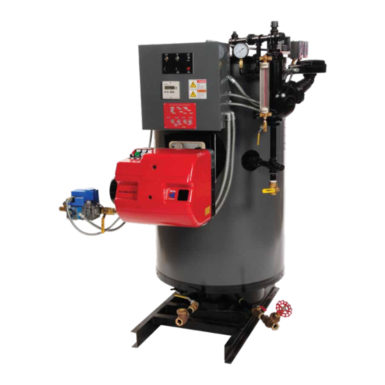
Summary of Contents for Lattner Boiler Company WLF 9.5 HP
- Page 1 INSTRUCTION MANUAL WLF MODELS 9.5 HP TO 50 HP Lattner Boiler Company 1411 9 St. SW Cedar Rapids, IA 52404 T: (800) 345-1527 F: (319) 366-0770 info@lattner.com www.lattnerboiler.com...
- Page 2 WARRANTY VALIDATION & BOILER START UP REPORT The following information must be recorded during each boiler start up. This information must be returned to Lattner Boiler Manufacturing Company for warranty validation. If this information is not returned, warranty consideration may not be extended. Lattner Boiler Model: Owner Name: National Board Number (“NB”):...
-
Page 3: Table Of Contents
Index General Description ..................Page 4 A. Boiler Design ....................4 B. Boiler Connections ....................4 C. Boiler Trim ································································································5 D. Fuel Burning System ....................6 E. Fuel Train ....................6 F. Control Panel ....................6 G. Combustion Safeguard ....................6 H. - Page 4 Installation F. Sight Glass Removal & Re- ······························································································22 Installation G. McDonnell Miller Servicing ······························································································23 H. Cleaning Interconnecting Pipe ······························································································23 Aux LWCO Relay Replacement ······························································································24 J. Auxiliary Low Water Cut-Off ······························································································24 Probe Cleaning Section IV: Troubleshooting ..................Page 25 A. Normal Operation ....................
-
Page 5: General Description
General Description WARNING: All installation procedures must be followed completely by a competent installer familiar with boilers and boiler accessories. CAUTION: Read and follow all instructions before installing any boiler equipment. All cover plates, enclosures and guards must be maintained and in place at all times, except during maintenance and servicing. A. -
Page 6: Boiler Trim
Boiler Slowdown Valve/Drain 5. Auxiliary Low Water Cut-Off An additional control, separate from the primary low A boiler blowdown valve is provided on the front right side of the pressure vessel to completely drain the boiler water control is provided to prevent burner operation if a as required, and for periodic bottom blowdown. -
Page 7: Fuel Train
Ignition/Pilot 2. Pump ON/OFF Switch Provided to isolate the pump control circuit. Gas-fired units are equipped with a spark ignited gas pilot assembly. The gas pilot assembly includes a pilot gas cock, gas pressure regulator, ignition transf o rmer, 3. Terminals and pilot solenoid valve. -
Page 8: Factory Tests
Factory Tests Burner/Controls To ensure proper operation of the combustion Pressure Vessel safeguard control, ignition, and main fuel light off the The boiler is subjected to an ASME certified hydrostatic burner manufacturer subjects the packaged burner to a pressure test to ensure the pressure vessel meets the preliminary factory fire test. -
Page 9: Section I: Installation
Section I: Installation WARNING: All installation procedures must be followed completely by a competent installer familiar with boilers and boiler accessories. CAUTION: Read and follow all instructions before installing any boiler equipment. All cover plates, enclosures and guards must be maintained and in place at all times, except during maintenance and servicing. A. -
Page 10: Stack
Wiring If there is other equipment in the room that uses air (large water heaters, air compressors, other boilers, exhaust fans, etc.), additional venting capacity is Re-wiring the controls will be covered in L: Electrical required. Connections. DO NOT connect the power supply at this time. -
Page 11: Safety Valve
Boilers operating 16 psi to 100 psi inclusive require a y 9. Aftercooler type gate or a ball valve rated for 125 WSP. If the water must be cooled before entering the sewer Boilers operating 101 psi to 150 psi require piping (required by some codes), then an aftercooler must be designed for a pressure of 125% of the boiler safety used. -
Page 12: Boiler Feed Systems
Make-Up Water Supply Diaphragm Gas Valve This valve is the main gas valve. A separate gas Connect city water line to the float valve provided pressure regulator must be used to regulate main burner with the boiler feed system. pressure. LVS through LV3S use 1/2"... -
Page 13: Electrical Connections
Check for Leaks boiler. All pipe is 1/2" NPT. Water Supply While the boiler is filling, check for leaks in the piping and around boiler. If there are leaks, turn off the pump Connect water supply to the strainer. switch and fix all leaks before continuing. L. -
Page 14: Start Up Of Standard Burners
auxiliary safety cut-off. The limit switch is supplied with a 10. More Information manual reset function. If the steam pressure trips the high limit switch, the limit locks in the off position. The For any additional information on the Honeywell limit switch will not reset until the manual reset lever is Pressuretrols, refer to the Honeywell product sheet in pressed. - Page 15 16. Check for Gas Leaks 19. Pressuretrols Allow the boiler to reach its operating pressure. Check Brush a soapy water solution on each connection in the the pressuretrols to be certain they're are set as main gas and pilot gas lines. Look for bubbles. If there described and functioning properly.
-
Page 16: Section Ii: Boiler Care
Section II: Boiler Care CAUTION: Read and follow all instructions before servicing any boiler. A. General The oxygen will then attack exposed metal surfaces. This leads to corrosion and localized pitting of the metal. The life expectancy of any boiler will depend on the routine care given to the boiler. -
Page 17: Foaming, Bouncing, & Chemicals
Generally, boiler feedwater will contain oxygen and treatment. Whenever a softener is used, chemical treatment dissolved minerals. Inside the boiler, the heat will cause is still necessary for oxygen scavenging and controlling pH. the oxygen to separate from the water. F. -
Page 18: Burner Adjustment
the vent pipe from the condensate return tank. If there is The boiler and the boiler level controls should be blown an abnormally high steam flow from the vent, either the down at least DAILY. traps or check valves are leaking. L. -
Page 19: Internal Inspections
Always be certain the sight glass is cut to proper length. Make sure the fixtures are plumb. If these two conditions are not checked, the glass may crack. M. Internal Inspections Gaskets Purpose of Inspections The hand hole gaskets and the McDonnell Miller head gasket must be replaced after each internal inspection. -
Page 20: Section Ill: Maintenance
Section Ill: Maintenance WARNING: All maintenance procedures must be followed completely by competent personnel familiar with boilers and boiler accessories. CAUTION: Read and follow all instructions thoroughly before working on any boiler equipment. NOTE: Certain maintenance items concerning specific components may be found in the product literature specifications section of this manual. - Page 21 D. Table 1: Recommended Testing Schedule ..--... Gauqes and Siqht Glass Daily Operator Make visual insoection and record readinqs in a loa. Instrument and Boiler Settings Daily Operator Make visual check against manufacturer's recommended specifications. Refer to product literature sheets. Low Water Fuel Cut-Off Monthly Operator...
-
Page 22: Hand Hole Plate Removal & Re
Hand Hole Plate Removal & Re- Figure 1 Installation Disconnect all power to the boiler. The boiler must be cool and drained of all water. See assembly print for hand hole location. Remove the hand hole plate nut. Use a 7 /8" socket. Gasket Remove arch over hand hole plate. - Page 23 F. Sight Glass Removal & Re-Installation / Brass Washer · Boiler and pump should be switched off. Sightglass Boiler should be cool and the water level should be below the lower water gauge fixture. Close the upper and lower water gauge valves. Loosen both sight glass packing nuts (top and bottom) with a wrench.
- Page 24 McDonnell Miller Servicing 16. Flush out all piping with water after cleaning. Disconnect all power to the boiler. 17. Replace all pipe plugs and pipe caps. Tighten with a wrench enough to prevent water or steam leaks. The boiler should be cool and drained of all water just below the McDonnell Miller control.
- Page 25 Auxiliary Low Water Cut-Off Probe Aux LWCO Relay Replacement Cleaning Disconnect all power to the boiler. Disconnect all power to the boiler. Pull r elay out by hand. This may take a little force but be careful. Remove the f our screws on top o f the probe enclosure with a Phillips screwdriver.
- Page 26 Section IV: Troubleshooting WARNING: All troubleshooting procedures must be followed completely by competent personnel familiar with boilers and accessories. CAUTION: Read and follow all instructions before troubleshooting any boiler equipment. A. Normal Operation C. Before You Begin All Lattner forced draft gas-fired boilers follow the same Before you begin any troubleshooting procedures, check the operating sequence: following:...
- Page 29 Lattner neither assumes nor authorizes any person to assume for it any other liability in connection with the sale or use of the boiler or other equipment manufactured by Lattner, and there are no oral agreements or warranties collateral to or affecting this Agreement. LATTNER BOILER COMPANY Cedar Rapids, IA USA Form W01-17...
- Page 30 Purchaser and the lower, less the applicable restocking charge. Company and their respective heirs, successors, or assigns. LATTNER BOILER COMPANY Cedar Rapids, IA USA TC17...
- Page 31 WATER GAUGE & GAUGE GLASS INSTALLATION GUIDE 20100, 20200, 20300, 20400, 20600, 20700, 20800, 21100, 21200, 22000, 22100, 22200, 23400, 23600, 24300, 24400, 24600, 24700, 24800, 25200, 25400, 25500, 25600, 20LF SERIES TOP GAUGE FITTING Only properly trained personnel should install and maintain water gauge glass and connections.
- Page 32 WATER GAUGE GLASS WATER GAUGE GLASS DO's READ ALL WARNINGS AND NOTICE: INSTRUCTIONS BEFORE DO verify proper gauge has been supplied. PERFORMING INSTALLATION OR MAINTENANCE. DO examine gauge glass and packings carefully for damage before installation. WARNING! DO install protective guards and utilize automatic ball checks where necessary to help prevent injury in case of glass SAFETY GLASSES AND GLOVES...
- Page 36 McDonnell & Miller Installation & Maintenance Instructions MM-217(I) Series 150S and 157S ® (Snap Switch, All Models except 157S-RB-P) Low Water Cut-Off/Pump Controllers For Steam Boilers and Other Level Control Applications Typical Applications: Series 150S – Primary or secondary pump controller/ low water fuel cut-off for steam boilers –...
- Page 37 OPERATION Maximum Pressure: 150 psi (10.5 kg/cm Electrical Ratings Alarm Circuit Rating Motor Horsepower PumpCircuit Rating (Amperes) Voltage Amps Voltage Voltage Full Load Locked Rotor Pilot Duty 120 VAC 120 VAC 120 VAC 44.4 345 VA at 120 or 240 VAC 240 VAC 22.2 240 VAC...
- Page 38 Settings and Differential Pressures (continued) Values are ± 8” (3.2mm). Model 158S Model 158S-MD Approximate Approximate Distance Above Distance Above Cast Line Differential Cast Line Differential Pressure Setting In. (mm) In. (mm) Pressure Setting In. (mm) In. (mm) Motorized (24) Pump Off (24) 0 psi...
- Page 39 Settings and Differential Pressures (continued) Values are ± 8” (3.2mm). Model 159S Approximate Distance Above Cast Line Differential Pressure Setting In. (mm) In. (mm) Pump #1 Off (24) 0 psi Pump #1 On (16) (0 kg/ Pump #2 Off (16) (16) Pump #2 On (6.4)
- Page 40 INSTALLATION TOOLS NEEDED: IMPORTANT: Follow the boiler manufacturer's Two (2) pipe wrenches, one (1) flathead screw instructions along with all applicable codes and driver, and pipe sealing compound. ordinances for piping, blow down valve and water gauge glass requirements. STEP 1 - Determine the Elevation at Which the Low Water Cut-Off/Pump Controller Must be Installed STEAM EQUALIZING PIPE If the control will be the primary low...
- Page 41 Models 150S-B Series 157S b. For Model 150S-B and Series 157S (For all other models, proceed to Step 3). Screw the w” NPT steel plug (C) (provided) in tapping (A). CAUTION The plug must be reinstalled before control is shipped installed on the boiler, and removed when boiler is installed after shipment.
- Page 42 STEP 4 - Electrical Wiring WARNING • To prevent a fire, do not use this product to switch currents over 7.4A, 1/3 Hp at 120 VAC or 3.7A, 1/3 Hp at 240 VAC, unless a starter or relay is used in conjunction with it. •...
- Page 43 b. Following the appropriate wiring diagram, (refer IMPORTANT: There must be to page 9) based on your application require- a minimum space of 1/2” ments, and using BX armored cable or Thinwall (13mm) between connector electrical metal tubing connector fittings, make fittings and electrical live electrical connections to the junction box (L).
- Page 44 WIRING DIAGRAMS For Motorized Valves, refer to the valve manufacturer's wiring instructions. Low Water Cut-Off Only 1. Main Line Switch - For burner circuits within the 2. Pilot Switch - To holding coil of a starter when switch’s electrical rating. the burner circuit exceeds the switch’s electrical rating.
- Page 45 6. Re-attach the junction box cover (K). Note: Cover must be installed correctly as shown STEP 5 - Testing This control is factory calibrated for specific applications. The following testing procedure is only meant to serve as a verification of proper operating sequence. Dimensions provided are typical for a boiler not being fired and/or not at pressure.
- Page 46 c. For automatic reset models only. When the water Snap Switch Models level reaches approximately d” (22mm) above the horizontal cast line (lower for MD models) the burner should come on (pump #2 should shut off with Model 159S). For manual reset models only. When the water level reaches approximately d”...
- Page 47 MAINTENANCE BLOW DOWN PROCEDURE: SCHEDULE: CAUTION Blow down control as follows when boiler is To prevent serious personal injury from steam in operation. pipe blow down, connect a drain pipe to the control opening to avoid exposure to steam • Daily if operating pressure is above 15 psi. discharge.
- Page 48 ProtoDesign Inc. 50495 Corporate Dr. Suite 106 Utica MI. 48315 Phone: 586-739-4340 Fax: 586-739-4341 www.teampdi.com INSTALLATION & OPERATING INSTRUCTIONS FOR THE FLW CONTROL This document should be used by trained personnel as a guide Single Level Service - Direct Mode: When the liquid rises to the to install the ProtoDesign Inc.
- Page 49 DIMENSIONAL DRAWING IONAL DRAWING 2.500 in 1.825 in 0.200 in 0.000 in TYPICAL WIRING DIAGRAM AC SUPPLY Transformer TRANSFORMER Tran sfom N.C.1 N.C.2 COM1 COM2 N.O.2 N.O.1 RESET RESET GROUND PROBE TANK CAN BE USED AS SHOULD BE LONGEST GROUND IF METALLIC MODEL NUMBER DESIGNATIONS FLW - X - X - X - X - XX-XX-XX - X OPTIONAL CHARACTERS (any combination):...
- Page 50 ProtoDesign Inc. 50495 Corporate Dr. Suite 106 Utica MI. 48315 Phone: 586-739-4340 Fax: 586-739-4341 www.teampdi.com INSTALLATION & OPERATING INSTRUCTIONS FOR THE LW CONTROL OPERATION: This document should be used by trained personnel as a guide to install the ProtoDesign Inc. low water control. Follow necessary TEST FEATURE (Option A) Allows the LWCO circuit to be wiring practices as defined by the national electric code (NEC).
- Page 51 DIMENSIONAL DRAWING IONAL DRAWING TYPICAL WIRING DIAGRAM MODEL NUMBER DESIGNATION LW – X – X – X – X – XX – X OPTIONAL CHARACTERS (any combination): Blank, A=Test feature, C=Conformal Coat, D=RoHS, F=Alternate lockout FALLING LEVEL TIME DELAY: 03 = 3 sec. (Standard), 30 = 30 sec. MODE: A = Direct (Standard) SUPPLY VOLTAGE: 1=120VAC (Standard), 2 = 240VAC, 3 = 220VAC, 4 = 24VAC (240VAC and 220VAC for operating control only, not for limit control)
- Page 62 Instructions Pressure Controls KP 35, KP 36 and KP 37 KP 35, KP 36, KP 37 max. test min. –40 C KP 35: 22 bar max. 65C KP 36: 22 bar KP 37: 32 bar min. –40 C max. 100C No maintenance is required for the controls after fi...
- Page 63 Contact system with standard AG contacts Contact system with gold contacts Single pole changeover switch (SPDT) Single pole changeover switch (SPDT) Alternating current: Alternating current: AC-1: 16, 400 V AC-1: 10, 400 V AC-3: 16A, 400 V AC-3: 6A, 400 V AC-15: 10A, 230 V AC-15:...
Need help?
Do you have a question about the WLF 9.5 HP and is the answer not in the manual?
Questions and answers