
Related Manuals for ASRock Industrial iEP-5000G Series

Summary of Contents for ASRock Industrial iEP-5000G Series
- Page 1 Series iEP-5000G-Series User Manual iEP-5010G-Series Version 1.0 Published April 2022 User Manual...
- Page 2 ASRock Industrial has been advised of the possibility of such damages arising from any defect or error in the documentation or product.
- Page 3 Important Safety Instructions For user safety, please read and follow all instructions, Warnings, Cautions, and Notes marked in this manual and on the associated device before handling/operating the device, to avoid injury or damage. 1. Read these safety instructions carefully. 2.
- Page 4 FSP065-RBBN3) suitable for use at TMA 40 °C (104 °F) min., and the output is rated 19 Vdc, 3.42A min., ES1. If you need further assistance, contact ASRock Industrial for additional information. 19. The terminal block is suitable for V+& V- for 14~28AWG. The torque value is 0.19Nm.
- Page 5 WARNING Input voltage rated 6-36V, 8-1.81A (iEP-5000G Series) Packing: The unit should be carried with both hands and handled with care. Maintenance: Use only approved products or a dry applicator to clean and maintain the...
- Page 6 HDMI Licensing LLC in the United States and other countries. Contact Information If you need to contact ASRock Industrial or want to know more about ASRock Industrial, you’re welcome to visit ASRock Industrial’s website at www.asrockind.com; or you may contact your dealer for further information.
-
Page 7: Table Of Contents
Contents Chapter 1 Introduction Package Contents Order Information Optional Items Product Specifications 1.4.1 System : iEP‐5000G‐000 1.4.2 System : iEP‐5000G‐010 1.4.3 System : iEP‐5000G‐001 1.4.4 System : iEP‐5000G‐002 1.4.5 System : iEP‐5000G‐003 1.4.6 System : iEP‐5001G‐000 1.4.7 System : iEP‐5010G‐010 1.4.8 System : iEP‐5010G‐011 1.4.9... - Page 8 2.2.2 System : iEP-5000G-001, iEP-5000G-002, iEP-5010G-011, iEP- 5010G-012, iEP-5010G-013 Inside View Position Chapter 3 Hardware Installation How to Remove the Front Cover How to Install the Wi-Fi Module (2230) to the M.2 E Key Slot (Optional) How to Install the 4G LTE/5G Module (3042/3052) to the M.2 B Key Slot (Optional) How to Install the M.2 SSD with the Heasink (M.2 Key M Socket (2280))
- Page 9 Chapter 5 UEFI Setup Utility Introduction 5.1.1 Entering BIOS Setup 5.1.2 UEFI Menu Bar 5.1.3 Navigation Keys Main Screen Advanced Screen 5.3.1 CPU Configuration 5.3.2 Chipset Configuration 5.3.3 Intel(R) Time Coordinated Computing 5.3.4 Storage Configuration 5.3.5 Super IO Configuration 5.3.6 ACPI Configuration 5.3.7 USB Configuration...
-
Page 10: Chapter 1 Introduction
iEP-5000G/5010G Series Chapter 1 Introduction Because the hardware specifications might be updated, the content of this documentation will be subject to change without notice. 1.1 Package Contents iEP-5000G-000 Series • 1 x iEP-5000G-000/iEP-5001G-000 • 1 x 65W Adaptor with screw type •... - Page 11 iEP-5000G-010 Series • 1 x iEP-5010G-010 • 3 x Screws for M.2 Module • 1 x M.2 M key (2280) Storage Heatsink • 1 x DRAM Heatsink • 1 x Phoenix plug connector iEP-5010G-010 Series • 1 x iEP-5010G-010 • 3 x Screws for M.2 Module •...
-
Page 12: Order Information
iEP-5000G/5010G Series 1.2 Order Information Model Name Description iEP-5000G-000 90PXG8D0-00000010 Basic SKU with CPU x6425RE, BASIC, DC JACK w/ Adapter 65W, w/o DRAM Storage, Mount iEP-5000G-010 90PXG8D0-30000000 Basic SKU with CPU x6425RE, DC PHX Type, w/o Adapter, DRAM, Storage, Mount iEP-5000G-001 90PXG8D0-10000020 PoE SKU with CPU x6425RE, DC JACK w/... -
Page 13: Optional Items
1.3 Optional Items Model Name PN Description Wall Mount 13G020760000AI Attach the wall mounting brackets to the iEP- Kits 5000G Series. Din Rail Kits 13G020761000AI Attach the din-rail brackets to the iEP-5000G Series and can place to the din rail. 2.5”... -
Page 14: Product Specifications
iEP-5000G/5010G Series 1.4 Product Specifications 1-6-1 System : iEP-5000G-000 1.4.1 System : iEP‐5000G‐000 Intel® Atom® X6425RE Quad-Core SoC Frequency 1.90 GHz Processor BIOS AMI EFI 256 Mbit Technology DDR4 3200 MHz (Support In-Band ECC) Memory Max Capacity 32GB Socket Dual 260-pin SO-DIMM Chipset Intel®... -
Page 15: System : Iep-5000G-010
1-6-2 System : iEP-5000G-010 1.4.2 System : iEP‐5000G‐010 Intel® Atom® X6425RE Quad-Core SoC Frequency 1.90 GHz Processor BIOS AMI EFI 256 Mbit Technology DDR4 3200 MHz (Support In-Band ECC) Memory Max Capacity 32GB Socket Dual 260-pin SO-DIMM Chipset Intel® UHD Graphics for 10th Gen Intel® Processors Graphics HDMI Up to 4096 x 2160 @ 60 Hz... -
Page 16: System : Iep-5000G-001
iEP-5000G/5010G Series 1.4.3 System : iEP‐5000G‐001 1-6-3 System : iEP-5000G-001 Intel® Atom® X6425RE Quad-Core SoC Frequency 1.90 GHz Processor BIOS AMI EFI 256 Mbit Technology DDR4 3200 MHz (Support In-Band ECC) Memory Max Capacity 32GB Socket Dual 260-pin SO-DIMM Chipset Intel®... -
Page 17: System : Iep-5000G-002
1.4.4 System : iEP‐5000G‐002 1-6-4 System : iEP-5000G-002 Intel® Atom® X6425RE Quad-Core SoC Frequency 1.90 GHz Processor BIOS AMI EFI 256 Mbit Technology DDR4 3200 MHz (Support In-Band ECC) Memory Max Capacity 32GB Socket Dual 260-pin SO-DIMM Chipset Intel® UHD Graphics for 10th Gen Intel® Processors Graphics HDMI Up to 4096 x 2160 @ 60 Hz... -
Page 18: System : Iep-5000G-003
iEP-5000G/5010G Series 1-6-5 System : iEP-5000G-003 1.4.5 System : iEP‐5000G‐003 Intel® Atom® X6425RE Quad-Core SoC Frequency 1.90 GHz Processor BIOS AMI EFI 256 Mbit Technology DDR4 3200 MHz (Support In-Band ECC) Memory Max Capacity 32GB Socket Dual 260-pin SO-DIMM Chipset Intel®... -
Page 19: System : Iep-5001G-000
1-6-5 System : iEP-5001G-000 1.4.6 System : iEP‐5001G‐000 Intel® Atom® X6212RE Dual-Core SoC Frequency 1.50 GHz Processor BIOS AMI EFI 256 Mbit Technology DDR4 3200 MHz (Support In-Band ECC) Memory Max Capacity 32GB Socket Dual 260-pin SO-DIMM Chipset Intel® UHD Graphics for 10th Gen Intel® Processors Graphics HDMI Up to 4096 x 2160 @ 60 Hz... -
Page 20: System : Iep-5010G-010
iEP-5000G/5010G Series 1-6-6 System : iEP-5010G-010 1.4.7 System : iEP‐5010G‐010 Intel® Atom® X6416RE Quad-Core SoC Frequency 1.70 GHz Processor BIOS AMI EFI 256 Mbit Technology DDR4 3200 MHz (Support In-Band ECC) Memory Max Capacity 32GB Socket Dual 260-pin SO-DIMM Chipset Intel®... -
Page 21: System : Iep-5010G-011
1.4.8 System : iEP‐5010G‐011 1-6-7 System : iEP-5010G-011 Intel® Atom® X6416RE Quad-Core SoC Frequency 1.70 GHz Processor BIOS AMI EFI 256 Mbit Technology DDR4 3200 MHz (Support In-Band ECC) Memory Max Capacity 32GB Socket Dual 260-pin SO-DIMM Chipset Intel® UHD Graphics for 10th Gen Intel® Processors Graphics HDMI Up to 4096 x 2160 @ 60 Hz... -
Page 22: System : Iep-5010G-012
iEP-5000G/5010G Series 1-6-8 System : iEP-5010G-012 1.4.9 System : iEP‐5010G‐012 Intel® Atom® X6416RE Quad-Core SoC Frequency 1.70 GHz Processor BIOS AMI EFI 256 Mbit Technology DDR4 3200 MHz (Support In-Band ECC) Memory Max Capacity 32GB Socket Dual 260-pin SO-DIMM Chipset Intel®... -
Page 23: System : Iep-5010G-013
1-6-5 System : iEP-5010G-013 1.4.10 System : iEP‐5010G‐013 Intel® Atom® X6416RE Quad-Core SoC Frequency 1.70 GHz Processor BIOS AMI EFI 256 Mbit Technology DDR4 3200 MHz (Support In-Band ECC) Memory Max Capacity 32GB Socket Dual 260-pin SO-DIMM Chipset Intel® UHD Graphics for 10th Gen Intel® Processors Graphics HDMI Up to 4096 x 2160 @ 60 Hz... -
Page 24: Block Diagram
iEP-5000G/5010G Series 1.5 Block Diagram DSB-1000-WT HDMI DDI0 Channel A DDR4 3200M HZ HDMI Retimer SO-DIMM Connector IT66318FN DDI1 Channel B DDR4 3200M HZ Realtek SO-DIMM RTD2168 SGMII(#8) PCIe x1(#0) LAN1 RJ45 GPY115 Connector USB3.2 Gen2(#0) Nano SIM Card M.2 Key B USB2.0(P0) SGMII(#7) RJ45... - Page 25 DSB-1010-WT HDMI HDMI DDI0 Channel A DDR4 3200M HZ SO-DIMM Connector IT66318FN DDI1 Realtek Channel B DDR4 3200M HZ SO-DIMM RTD2168 PCIe x1(#0) M.2 KEY-E PCIex1 (2230) USB3.2 Gen2(#0) M.2 Key B Nano SIM Card USB2.0(P0) PCIex1 RJ45 LAN2 ASM2806I PCIex2(#8,#9) Connector WG210AT...
-
Page 26: Chapter 2 Product Overview
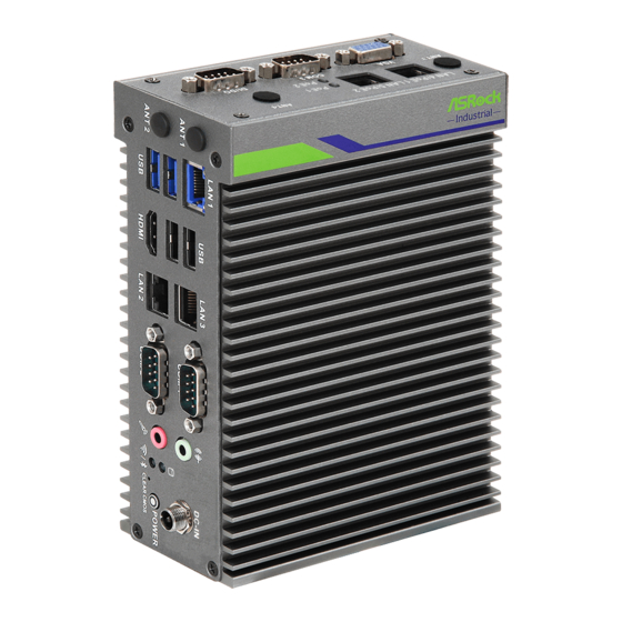
iEP-5000G/5010G Series Chapter 2 Product Overview This chapter provides diagrams showing the location of important components of the iEP-5000G/5010G Series. 2.1 System Front Panel 2.1.1 System : iEP-5000G-000, iEP-5000G-001, iEP-5000G-002, iEP-5000G-003 11 12 13 14... - Page 27 Description Antenna Holes : The antenna hole allows you to connect a wireless antenna to enhance wireless signal reception. LAN port* : The RJ-45 LAN port supports a standard Ethernet cable for 10/100/100 Mbps connection to local network. USB 2.0 : The USB port is compatible with USB 2.0 or USB 1.1 devices. Serial (COM) Ports : The 9-pin RS232/422/485 serial connector allows you to connect devices that have serial ports.
-
Page 28: System : Iep-5000G-010, Iep-5010G Series
iEP-5000G/5010G Series 2.1.2 System : iEP-5000G-010, iEP-5010G Series 11 12 13 14... - Page 29 Description Antenna Holes : The antenna hole allows you to connect a wireless antenna to enhance wireless signal reception. LAN port* : The RJ-45 LAN port supports a standard Ethernet cable for 10/100/100 Mbps connection to local network. USB 2.0 : The USB port is compatible with USB 2.0 or USB 1.1 devices. Serial (COM) Ports : The 9-pin RS232/422/485 serial connector allows you to connect devices that have serial ports.
- Page 30 iEP-5000G/5010G Series * There are two LEDs on the LAN port. Please refer to the table below for the LAN port LED indications. ACT/LINK LED SPEED LED LAN Port Activity / Link LED Speed LED Status Description Status Description No Link 10Mbps connection Blinking Data Activity...
-
Page 31: System Top Panel
2.2 System Top Panel 2.2.1 System : iEP-5000G-000, iEP-5000G-010, iEP-5010G-010 Description Antenna Holes : The antenna holes allow you to connect 5G wireless antenna to enhance wireless signal reception. VGA : Use a VGA cable to connect between the system and your monitor. Signal Signal RED_VGA... - Page 32 iEP-5000G/5010G Series Digital I/O : The 9-pin Digital Input / Output connector allows you to program it for input or output use. Signal Name PMC_TGPIO0 PCH_GP02 SIO_GP34 SIO_GP36 PCH_GP01 PCH_GP03 SIO_GP35 SIO_GP37...
-
Page 33: System : Iep-5000G-001, Iep-5000G-002, Iep-5010G-011, Iep- 5010G-012, Iep-5010G-013
2.2.2 System : iEP-5000G-001, iEP-5000G-002, iEP-5010G-011, iEP- 5010G-012, iEP-5010G-013 Description Antenna Holes : The antenna holes allow you to connect 5G wireless antenna 1, 4 to enhance wireless signal reception. LAN4/PoE1 & LAN5/PoE2 : The RJ-45 LAN ports support a standard Ethernet cable for connection to local network, and support PoE. - Page 34 iEP-5000G/5010G Series Digital I/O : The 9-pin Digital Input / Output connector allows you to program it for input or output use. Signal Name PMC_TGPIO0 PCH_GP02 SIO_GP34 SIO_GP36 PCH_GP01 PCH_GP03 SIO_GP35 SIO_GP37...
-
Page 35: Inside View
2.3 Inside View Description M.2 Slot (E Key) : The M.2 slot allows you to install 2230 Wi-Fi/BT module. M.2 Slot (B Key) : The M.2 slot allows you to install 3042/3052 4G LTE/5G module. M.2 Slot (M Key) : The M.2 slot allows you to install 2280 M.2 devices. Memory : Dual Small Outline Dual Inline Memory module slots designed for DDR4 memory modules SATA 3.0 Connector : The SATA connector allows you to connect 2.5”... -
Page 36: Chapter 3 Hardware Installation
iEP-5000G/5010G Series Chapter 3 Hardware Installation This chapter helps you install or remove important components. 3.1 How to Remove the Front Cover 1. Remove the screws on the case. 2. Then lift up and remove the front cover. -
Page 37: How To Install The Wi-Fi Module (2230) To The M.2 E Key Slot (Optional)
3.2 How to Install the Wi-Fi Module (2230) to the M.2 E Key Slot (Optional) 1. Locate the WiFi Module slot on the motherboard. 2. Carefully insert the WiFi Module into the slot. 3. Tighten the screw to secure the WiFi Module to the motherboard. - Page 38 iEP-5000G/5010G Series Remove the antenna rubber on the box cover. Attach the SMA cable and washer to both sides of the cover, and secure them with the nut. Install the Wifi antenna onto the SMA cable.
-
Page 39: How To Install The 4G Lte/5G Module (3042/3052) To The M.2 B Key Slot (Optional)
3.3 How to Install the 4G LTE/5G Module (3042/3052) to the M.2 B Key Slot (Optional) 1. Locate the 4G LTE/5G Module slot on the motherboard. 2. Carefully insert the 4G LTE/5G Module into the slot. 3. Tighten the screw to secure the 4G LTE/5G Module to the motherboard. - Page 40 iEP-5000G/5010G Series Remove the antenna rubber on the box cover. Attach the SMA cable and washer to both sides of the cover, and secure them with the nut. Install the 4G LTE/5G antenna onto the SMA cable.
-
Page 41: How To Install The M.2 Ssd With The Heasink (M.2 Key M Socket (2280))
3.4 How to Install the M.2 SSD with the Heasink (M.2 Key M Socket (2280)) 1. Gently insert the M.2 module, along the guiding tabs, into the heatsink bracket. 2. Remove the membrane from heatsink. Align the heatsink to the edge of the bracket and press down the heatsink into the bracket. - Page 42 iEP-5000G/5010G Series 4. Tighten the screw to secure the M.2 module and the heatsink to the motherboard.
-
Page 43: How To Install The Memory Modules And The Heatsinks
3.5 How to Install the Memory Modules and the Heatsinks For dual channel configuration, you always need to install identical (the same brand, speed, size and chip-type) DDR4 SO-DIMM pairs. The SO-DIMM only fits in one correct orientation. It will cause permanent damage to the motherboard and the DIMM if you force the DIMM into the slot at incorrect orientation. - Page 44 iEP-5000G/5010G Series 3. Remove the membrane from heatsink. Then paste the heatsink onto the module.
-
Page 45: How To Install The 2.5-Inch Hard Drive (Optional, For Iep-50X0G-000/010 Only)
3.6 How to Install the 2.5-inch Hard Drive (Optional, for iEP- 50X0G-000/010 only) 1. Remove the screws on the case. Then lift up and remove the front cover. 2. Attach the 2.5'' SSD to the SSD bracket and secure it with four screws. Then connect the SATA cable to the SSD. - Page 46 iEP-5000G/5010G Series 3. Attach the SSD assembly to the front cover and secure it with four screws. 4. Connect the SATA connector and Power Cable to the motherboard. 5. Then reinstall the front cover.
-
Page 47: How To Install A Nano Sim Dard And Micro Sd Card
3.7 How to Install a Nano SIM Dard and Micro SD Card 1. Release the screws on the iEP-5000G/5010G Series and remove the SIM/Micro SD Card slot cover.. 2. With the gold contacts facing front, carefully insert the SIM Card or the SD Card into the designated slot until it clicks.. - Page 48 iEP-5000G/5010G Series 3. Place the cover back and secure it to the iEP-5000G/5010G Series with screws.
-
Page 49: How To Install The Wall Mounting Bracket (Optional)
3.8 How to Install the Wall Mounting Bracket (Optional) 1. Attach the wall mounting brackets to the iEP-5000G/5010G Series and secure it with screws. 2. Then you can attach the iEP-5000G/5010G Series to the wall with screws. - Page 50 iEP-5000G/5010G Series Dimension of the iEP-5000G/5010G Series with Wall Mounting Bracket Installed 100mm 86mm 42mm 53mm Wall Mounting Bracket is not provided by default. Please purchase it separately if needed.
-
Page 51: How To Install The Din Rail Mounting Bracket (Optional)
3.9 How to Install the Din Rail Mounting Bracket (Optional) 1. Attach the Din Rail Bracket to the iEP-5000G/5010G Series and secure it with screws. 2. Then you can place the iEP-5000G/5010G Series to the Din Rail. Admissible DIN rail : TS35/7.5 or TS35/15 Din Rail Bracket is not provided by default. -
Page 52: How To Install The 5G Module Heatsink (Optional)
iEP-5000G/5010G Series 3.10 How to Install the 5G Module Heatsink (Optional) 1. Remove the membranes on the both sides of the 5G module heatsink. 2. Attach the 5G Module Heatsink to the internal side of the front cover and secure it with screws. -
Page 53: Chapter 4 Motherboard
Chapter 4 Motherboard 4.1 Motherboard Layout 4.1.1 iEP-5000G MB (DSB-1000-WT) Top Side : VGA1 JGPIO1 COM3 JGPIO_SET1 DDR4_A1 USB 3.2 Gen2 Top: T: USB3_2 LAN1 B: USB3_1 DDR4_B1 USB 2.0 T: USB2_4 HDMI B: USB2_3 LAN2 LAN3 BIOS COM2 COM1 ESPI1 BAT1 Top: HDD LED... - Page 54 iEP-5000G/5010G Series Rear Side :...
- Page 55 1 : Digital Input/Output Connector (JGPIO1) 2 : COM Port (COM3) (RS232/422/485) 3 : D-Sub Port (VGA1) 4 : SATA3 Connector (SATA3_1) 5 : SATA Power Output Connector (SATA_PWR1) 6 : CAN Connector (CAN1_2) 7 : M.2 Key-E Socket (M2_E1) 8 : M.2 Key-B Socket (M2_B1) 9 : ATX/AT Mode Jumper (SIO_AT1) 10 : Clear CMOS Header (CLRMOS2)
-
Page 56: Iep-5010G Mb (Dsb-1010-Wt)
iEP-5000G/5010G Series 4.1.2 iEP-5010G MB (DSB-1010-WT) Top Side : VGA1 JGPIO1 COM3 JGPIO_SET1 DDR4_A1 USB 3.2 Gen2 Top: T: USB3_2 LAN1 B: USB3_1 DDR4_B1 USB 2.0 T: USB2_4 HDMI B: USB2_3 Industrial RoHS LAN2 LAN3 COM2 COM1 BIOS ESPI1 BAT1 Top: HDD LED Bottom: Wireless LED DC_IN1... - Page 57 Rear Side :...
- Page 58 iEP-5000G/5010G Series 1 : Digital Input/Output Connector (JGPIO1) 2 : COM Port (COM3) (RS232/422/485) 3 : D-Sub Port (VGA1) 4 : Chassis Intrusion Headers (CI1) 5 : SATA3 Connector (SATA3_1) 6 : SATA Power Output Connector (SATA_PWR1) 7 : CAN Connector (CAN1_2) 8 : M.2 Key-E Socket (M2_E1) 9 : M.2 Key-B Socket (M2_B1) 10 : ATX/AT Mode Jumper (SIO_AT1)
-
Page 59: Jumpers Setup
4.2 Jumpers Setup The illustration shows how jumpers are setup. When the jumper cap is placed on pins, the jumper is “Short.” If no jumper cap is placed on pins, the jumper is “Open. ” The illustration shows a 3-pin jumper whose pin1 and pin2 are “Short”... - Page 60 iEP-5000G/5010G Series DACC Jumper Setting Description Disabled Auto Clear (2-pin DACC1) Open CMOS (see p. 37, No. 12; p. 40, No. 13) Enabled Auto Clear Short CMOS (Default) Auto clear CMOS when system boot improperly. Digital Input/Output Default Value Setting Setting Description Pull-High (Default)
-
Page 61: Onboard Headers And Connectors
4.3 Onboard Headers and Connectors Onboard headers and connectors are NOT jumpers. Do NOT place jumper caps over these headers and connectors. Placing jumper caps over the headers and connectors will cause permanent damage to the motherboard! SATA3 Connector Signal name Signal Description Ground (see p. - Page 62 iEP-5000G/5010G Series Battery Connector (BAT1) (see p. 37, No. 14; p. 40, No. 16) Power Connector (Input 6V-36V) Setting Description (4-pin DC_IN1) DC Input (see p. 37, No. 15; p. 40, No. 17)
-
Page 63: Expansion Slots (M.2 Sockets)
4.4 Expansion Slots (M.2 Sockets) There are 3 M.2 sockets on both motherboards. Signal Signal M.2 Key-M Socket (M2_M1): +3.3V +3.3V (see p. 37, No.13; p. 40, No.14) SATA_LED +3.3V +3.3V +3.3V +3.3V M.2 Key M Socket (2242/2260/2280) supports NVMe with PCIex2/SATA for Storage PERn1 PERp1 PETn1... -
Page 64: Chapter 5 Uefi Setup Utility
Chapter 5 UEFI Setup Utility 5.1 Introduction ASRock Industrial UEFI (Unified Extensible Firmware Interface) is a BIOS utility which offers tweak-friendly options in an advanced viewing interface. The UEFI system works with a USB mouse and offers users a faster, sleeker experience. -
Page 65: Uefi Menu Bar
5.1.2 UEFI Menu Bar The top of the screen has a menu bar with the following selections: For setting system time/date information Main Advanced For advanced system configurations H/W Monitor Displays current hardware status Security For security settings Boot For configuring boot settings and boot priority Exit Exit the current screen or the UEFI Setup Utility Because the UEFI software is constantly being updated, the following UEFI setup... -
Page 66: Navigation Keys
iEP-5000G/5010G Series 5.1.3 Navigation Keys Use < > key or < > key to choose among the selections on the menu bar, and use < > key or < > key to move the cursor up or down to select items, then press <Enter>... -
Page 67: Main Screen
5.2 Main Screen When you enter the UEFI SETUP UTILITY, the Main screen will appear and display the system overview. Because the UEFI software is constantly being updated, the following UEFI setup screens and descriptions are for reference purpose only, and they may not exactly match what you see on your screen. -
Page 68: Advanced Screen
iEP-5000G/5010G Series 5.3 Advanced Screen In this section, you may set the configurations for the following items: CPU Configuration, Chipset Configuration, Intel(R) Time Coordinated Computing, Storage Configuration, Super IO Configuration, ACPI Configuration, USB Configuration, Trusted Computing , PSE Con- figuration, Serial Port Console Redirection, and External Ports Control. Setting wrong values in this section may cause the system to malfunction. -
Page 69: Cpu Configuration
5.3.1 CPU Configuration Active Processor Cores This allows you to select the number of cores to enable in each processor package. CPU C States Support This allows you to enable CPU C States Support for power saving. It is recommended to keep C3, C6 and C7 all enabled for better power saving. - Page 70 iEP-5000G/5010G Series SpeedStep technology. Configuration options: [Enabled] [Disabled]. Please note that enabling this function may reduce CPU voltage and lead to system stability or compatibility issues with some power supplies. Please set this item to [Disabled] if above issues occur. CPU Thermal Throttling CPU Thermal Throttling allows you to enable CPU internal thermal control mecha- nisms to keep the CPU from overheating.
-
Page 71: Chipset Configuration
5.3.2 Chipset Configuration Above 4G Decoding The option allows you to enable or disable above 4G Memory Mapped IO decoding. This is disabled automatically when Aperture Size is set to 2048MB. Configuration options: [Enabled] [Disabled] VT-d Intel® Virtualization Technology for Directed I/O helps your virtual machine monitor better utilize hardware by improving application compatibility and reliability, and providing additional levels of manageability, security, isolation, and I/O performance. - Page 72 iEP-5000G/5010G Series Render Standby Power down the render unit when the GPU is idle for lower power consumption. Onboard LAN3 This allows you to enable or disable the Onboard LAN3 feature. Smart-AZ This allows you to enable or disable Smart-AZ. Onboard HD Audio Select [Auto], [Enabled] or [Disabled] for the onboard HD Audio feature.
-
Page 73: Intel(R) Time Coordinated Computing
5.3.3 Intel(R) Time Coordinated Computing Intel TCC Mode The item enables or disables Intel(R) TCC Mode. When enabled, this will modify system settings to improve real-time performance. The full list of settings and their current state are displayed below when Intel(R) TCC mode is enabled. Software SRAM The item enables or disables Software SRAM. - Page 74 iEP-5000G/5010G Series GT CLOS The item enables or disables Graphics Technology(GT) Class of Service. Enable will reduce Gfx LLC allocation to minimize impact of Gfx workload on LLC.
-
Page 75: Storage Configuration
5.3.4 Storage Configuration SATA Controller(s) The option allows you to enable or disable the SATA controllers. Configuration options: [Enabled] [Disabled] SATA Mode Selection AHCI supports new features that improve performance. Configuration option: [AHCI] AHCI (Advanced Host Controller Interface) supports NCQ and other new features that will improve SATA disk performance but IDE mode does not have these advantages. - Page 76 iEP-5000G/5010G Series Hard Disk S.M.A.R.T. S.M.A.R.T stands for Self-Monitoring, Analysis, and Reporting Technology. It is a monitoring system for computer hard disk drives to detect and report on various indicators of reliability. Configuration options: [Enabled] [Disabled] SD Crad 3.0 Controller Use this item to enable or disable SD Crad 3.0 Controller.
-
Page 77: Super Io Configuration
5.3.5 Super IO Configuration COM1 Configuration Use this to set parameters of COM1. Type Select Use this to select COM1 port type: [RS232], [RS422] or [RS485]. COM2 Configuration Use this to set parameters of COM2. Type Select Use this to select COM2 port type: [RS232], [RS422] or [RS485]. COM3 Configuration Use this to set parameters of COM3. - Page 78 iEP-5000G/5010G Series DID2 Type Select Use this to set DIO Type: [Input]. DID3 Type Select Use this to set DIO Type: [Input]. DID4 Type Select Use this to set DIO Type: [Input]. DID5 Type Select Use this to set DIO Type: [Input]. DID6 Type Select Use this to set DIO Type: [Input].
-
Page 79: Acpi Configuration
5.3.6 ACPI Configuration Suspend to RAM Suspend to RAM allows you to select [Disabled] for ACPI suspend type S1. It is recommended to select [Auto] for ACPI S3 power saving. Configuration options: [Auto] [Disabled] PCIE Devices Power On Use this item to enable or disable PCIE devices to turn on the system from the power-soft-off mode. -
Page 80: Usb Configuration
iEP-5000G/5010G Series 5.3.7 USB Configuration USB Power Control Use this option to control USB power. M.2 Key_B Function The item enables or disables M.2 Key_B USB function. -
Page 81: Trusted Computing
5.3.8 Trusted Computing Security Device Support Security Device Support allows you to enable or disable BIOS support for security device. O.S. will not show Security Device. TCG EFI protocol and INT1A interface will not be available. Configuration options: [Enabled] [Disabled] Active PCR banks This item displays active PCR Banks. - Page 82 iEP-5000G/5010G Series Platform Hierarchy This item allows you to enable or disable Platform Hierarchy. Configuration options: [Enabled] [Disabled] Storage Hierarchy This item allows you to enable or disable Storage Hierarchy. Configuration options: [Enabled] [Disabled] Endorsement Hierarchy This item allows you to enable or disable Endorsement Hierarchy. Configuration options: [Enabled] [Disabled] TPM 2.0 UEFI Spec Version Select the TCG2 Spec Version Support, TCG_1_2: the Compatible mode for Win8/...
- Page 83 Onboard TPM The option enables or disables Intel PTT in ME. Disable this option to use discrete TPM Module.
-
Page 84: Pse Configuration
iEP-5000G/5010G Series 5.3.9 PSE Configuration PSE Controller Use this to enable or disable Programmable Service Engine (PSE) device. Shell This item allows you to enable or disable shell. Onboard LAN1 This allows you to enable or disable the Onboard LAN1 feature. Smart-AZ This item allows you to enable or disable Smart-AZ. -
Page 85: Serial Port Console Redirection
5.3.10 Serial Port Console Redirection Console Redirection Settings The settings specify how the host computer and the remote computer (which the user is using) will exchange data. Both computers should have the same or compat- ible settings. Console Redirection EMS Console Redirection Enable or Disable. -
Page 86: External Ports Control
iEP-5000G/5010G Series 5.3.11 External Ports Control USB3_1 SS Physical Connector Enable/Disable this USB Physical Connector (physical port). Once disabled, any USB devices plug into the connector will not be detected by BIOS or OS. USB3_1 HS Physical Connector Enable/Disable this USB Physical Connector (physical port). Once disabled, any USB devices plug into the connector will not be detected by BIOS or OS. - Page 87 USB3_4 HS Physical Connector Enable/Disable this USB Physical Connector (physical port). Once disabled, any USB devices plug into the connector will not be detected by BIOS or OS. Onboard LAN1 Select ownership for GBE. Onboard LAN2 Select ownership for GBE. Onboard LAN3 To Enable or Disable Onboard LAN.
-
Page 88: Hardware Health Event Monitoring Screen
iEP-5000G/5010G Series 5.4 Hardware Health Event Monitoring Screen In this section, it allows you to monitor the status of the hardware on your system, including the parameters of the CPU temperature, motherboard temperature, and the critical voltage. -
Page 89: Security Screen
5.5 Security Screen In this section, you may set, change or clear the supervisor/user password for the system. Supervisor Password Set or change the password for the administrator account. Only the administrator has the authority to change the settings in the UEFI Setup Utility. Leave it blank and press enter to remove the password. -
Page 90: Boot Screen
iEP-5000G/5010G Series 5.6 Boot Screen In this section, it will display the available devices on your system for you to configure the boot settings and the boot priority. Boot From Onboard LAN The item allows the system to be woke up by the onboard LAN. Configuration options: [Enabled] [Disabled] Setup Prompt Timeout The item allows you to... -
Page 91: Exit Screen
5.7 Exit Screen Save Changes and Exit When you select this option, the following message “Save configuration changes and exit setup?” will pop out. Select [Yes] to save the changes and exit the UEFI SETUP UTILITY. Discard Changes and Exit When you select this option, the following message “Discard changes and exit setup?”...
Need help?
Do you have a question about the iEP-5000G Series and is the answer not in the manual?
Questions and answers