Advertisement
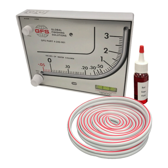
GFS MANOMETER
Installation & Operating Instructions
Each GFS Manometer includes:
Two tubing connectors for 1/8-inch pipe or sheet
•
metal ducts
Two mounting screws
•
1-ounce bottle of red indicating fluid
•
Red and green pointer flags
•
8 feet of double-column tubing
•
Instructions
•
NOTE: Contact Global Finishing Solutions at 800-848-8738 to speak to a
Technical Services Representative:
• To make sure the correct fluid is being used.
• If additional fluid (GFS part number 242-166) is required.
MOUNT THE MANOMETER
1. Position the manometer on the outside of the booth.
Note: Choose a convenient location, approximately
5 feet from the floor.
2. Drill two holes (1/8-inch or 9/64-inch) on a vertical
line 3-15/16 inches apart for the provided fittings.
3. Loosely mount manometer with the provided self-
tapping screws.
4. Adjust the gauge until the bubble is centered in the
level vial, then secure the manometer tightly.
12731 Norway Road | Osseo, Wisconsin 54758
800-848-8738 | globalfinishing.com
GFS Part Number: 242-001
Rev. 01172020
Advertisement
Table of Contents

Related Manuals for GFS 242-001

Summary of Contents for GFS 242-001
- Page 1 NOTE: Contact Global Finishing Solutions at 800-848-8738 to speak to a Technical Services Representative: • To make sure the correct fluid is being used. • If additional fluid (GFS part number 242-166) is required. MOUNT THE MANOMETER 1. Position the manometer on the outside of the booth.
- Page 2 4. Clean with mild soap and water. Avoid any cleaning fluids that may result in damage to the gauge. NOTE: The instructions provided are for single-stage filtration with GFS Wave exhaust filters. Contact Global Finishing Solutions at 800-848-8738 and speak to a Technical Services Representative for: •...
Need help?
Do you have a question about the 242-001 and is the answer not in the manual?
Questions and answers