Advertisement
Quick Links
Thank you for choosing a NIVELCO instrument!
1. APPLICATION
The conductive measuring principle can be applied to liquids with specific conductivity over
10 μS/cm. The switching unit can sense the resistance between probes. Conductivity measure-
ment is suitable only for detecting the presence of liquid at a given level of the tank. This level
is represented by the length of the probe.
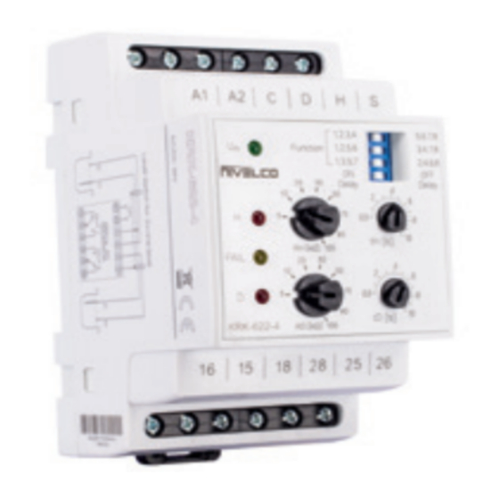
The level switch consists of a NIVOCONT KRK–622– type switching unit and the
KLN–2 type probes selected according to the task. Probes are to be connected to the
NIVOCONT KS– 0 type probe socket head that can be screwed into the tank.
If the material of the tank or its internal insulation is not conductive then a reference probe
should be used in addition to the one, two, three or four probe(s), if the material of the tank is
conductive, the tank can be used as a reference probe.
The conductive switch is suitable for filling-emptying control with 2 relay outputs working simul-
taneously or for level detection of 2 independent levels (in 1 or 2 tanks) with 2 independent relay
outputs. More level switches can also be used with one common reference probe 'C' using any
combination of multiple-probe and single-probe socket.
2. TECHNICAL DATA
2.1 GENERAL DATA
2.1.1 Switch
KRK–622–1, –2
Probe voltage
Probe current
Sensitivity
Max. cable capacitance
Response time
Mechanical accuracy
Delay
Relay output
Switching voltage
Switching current
Switching power
Min. output power DC
Mechanical life-span
Electrical life-span
230 V or 110 V AC
Power supply U
Galvanically separated (AC 50/60 Hz)
n
Voltage range allowed
Nominal voltage –15%...+10%
2.5 W / 5 VA (230 V AC, 110 V AC),
Power consumption
Ambient temperature
Electrical connection
Overvoltage category
Pollution degree
Electrical protection
Class II
Ingress protection
Mechanical connection
Weight
248 g (0.55 lb)
2.4 DIMENSIONS
Switch
KRK–622–
Uninsulated base probe
Probe Socket
KRK–512–
KRK–622–4
max. 3.5 V AC
< 1 mA AC
Adjustable: 5...100 kΩ
800 nF (sensitivity 5 kΩ)
100 nF (sensitivity 100 kΩ)
max. 400 ms
±5%
Adjustable: 0.5...10 s
2× SPDT
250 V AC1, 24 V DC
16 A AC1
4000 VA AC1, 384 W DC
4 kV (power – output)
3 × 10
switches
7
0.7 × 10
switches
5
24 V AC/DC
1.4 W / 2 VA (24 V AC/DC)
–20...+55 °C (–4...+131 °F)
max. 2.5 mm
(AWG14)
2
II
2
Class III
IP20
DIN EN 60715 rail
147 g (0.32 lb)
Pg7
Cable Probe
KSK–201
2.3 ACCESSORIES
– User's Manual
– Warranty Card
– EU declaration of conformity
– Seal (2 mm [0.08"] thick)
(KLINGER OILIT):
1× ⅜" (KSP–201, KSS–201, KSN–201)
1× 1½" (KSH–20)
– M6 nut (standard SW):
3× (KSH–202)
4× (KSH–203, KSH–204)
– M6 nut (non-st. SW)
1× (KSH–204)
2.1.2 Probe sockets
KSK–
KSP–
KSS–
201
201
201
Number of probes
1
Insulation of socket
ABS
PP
M4 nut,
Cable gland
Pg7
(1)
protected by a rubber cap
Process conn.
–
⅜" BSP
A44
Socket material
–
PP
c. steel
Housing material
–
max. +80 °C
Medium
temperature
(+176 °F)
3 bar
Max. pressure
–
(43.5 psi)
Ingress protection
–
IP20
50 g
Mass
100 g (0.22 lb)
(0.11 lb)
r = reference probe
2.2 ORDER CODES
(NOT ALL CODE VARIATION AVAILABLE)
KRK–622–
NIVOCONT KS
Power supply
Code
Type
1
230 V AC
Cable probe
110 V AC
2
24 V AC/DC
4
PP socket
Carbon steel socket
KLN–2
Stainless steel socket
Code
Probe length
Code
Stainless steel socket
0
0 m
0 m
0
1
5
1 m (3.3 ft) 0.5 m (1.64 ft)
2
2 m (6.6 ft)
3
3 m (10 ft)
M20x1.5
SW55
Probe Socket
KSH–20
M20x1.5
Separator
KLP–204
KSH–
KSN–
201
202
203
204
301
302
2+r
3+r
4+r
1+r
2+r
PFA
M20x1.5
cable diameter Ø6...12 mm (Ø0.25...0.5 inch)
1½" BSP
KO35
stainless steel (1.4571)
Powder-coated
cast aluminum
max. +200 °C (+391 °F)
max. +80 °C (+176 °F)
16 bar (232 psi)
3 bar (43.5 psi)
IP65
400 g (0.88 lb)
–
0
Code
Housing mat. Code
K
Aluminum
SINGLE PROBE
Plastic
P
S
N
MULTIPLE PROBES
Separator:
H
NIVOCONT KLP–201 – for plastic version
NIVOCONT KLP–204 – for aluminum version
⅜" BSP
Probe Socket
KSP–201 / KSS–201 / KSN–201
Probe Socket
KSH–30
NIVOCONT K
KRK–622
CONDUCTIVE LEVEL SWITCH
USER'S MANUAL
PDF
Manufacturer:
NIVELCO Process Control Co.
H–1043 Budapest, Dugonics u. 11.
Tel.: +36-1-889-0100
Fax: +36-1-889-0200
E-mail: sales@nivelco.com
www.nivelco.com
KLN–
KLP–
KLP–
2
201
204
303
304
3+r
4+r
1
–
PP
–
–
–
M6
–
KO35
PP
–
1.4571
PBT
–
PP
PVDF
max.
max.
–
+80 °C
+130 °C
(+176 °F)
(+266 °F)
–
IP67
–
220 g/m
–
(0.13 lb/ft)
cable: Ø4...7 mm
(1)
Probe number
Code
2
1 + reference probe*
1*
3
2 + reference probe
2
3
3 + reference probe
4 + reference probe
4
*only plastic version
Probe
KLN–2
Separator
KLP–201
krk622en1905h ♦ page 1
Advertisement

Related Manuals for NIVELCO NIVOCONT K


Summary of Contents for NIVELCO NIVOCONT K
- Page 1 NIVOCONT K Thank you for choosing a NIVELCO instrument! KRK–622 1. APPLICATION 2.3 ACCESSORIES CONDUCTIVE LEVEL SWITCH – User’s Manual The conductive measuring principle can be applied to liquids with specific conductivity over – Warranty Card 10 μS/cm. The switching unit can sense the resistance between probes. Conductivity measure- USER’S MANUAL...
- Page 2 3. INSTALLATION Example of setting DIP switch: Select the desired function in accordance with the figures. The upper 3 switches are for select- A KRK–622– switching unit can be mounted on DIN EN 60715 rail. ing the number of the function you want to use. If you want to use Function 5 you should set It is recommended the KLN–2...
- Page 3 FUNCTION 1 FUNCTION 5 – PUMP UP (FILLING), ON DELAY: Controlling level in 2 separate tanks (each with 1 probe) – filling. The pumps are running and fill the tanks until the levels reach the corresponding probes (E1 or E2). probe H Relay 1 (E1): Pump control 1 probe D...
- Page 4 Handling Form) must be filled and enclosed in the parcel. Download it from our website www.nivelco.com. The device must be sent back with a declaration of de- contamination. A statement must be provided in the declaration that the decontam- ination process was successfully completed and that the device is clean from any hazardous substances.