
Summary of Contents for GEA Fit R-300
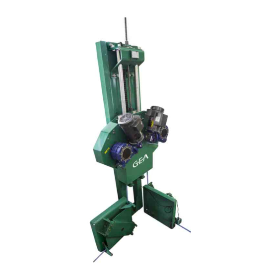
- Page 1 Fit R-300 Cable alley scraper Operation Manual / Installation Instructions (Original operating instructions) 2005-9015-009 01. August 2018 gea.com...
-
Page 2: Table Of Contents
............... . . GEA Farm Technologies Canada Inc. / Division GEA Houle - General equipment warranty . - Page 3 Handling and installation ..........Special personnel qualification required for handling and installation .
- Page 4 Programming ............Special personnel qualification required for programming .
- Page 5 Operating faults ............10.1 Special qualification required for troubleshooting .
-
Page 6: Preface
Preface About this manual Preface About this manual The manufacturer reserves the right to make changes due to technical developments in the data and illustrations in this manual. Reproductions, translations and copies of any kind, including extracts, require written authorization from the manufacturer. This manual is supplied with the product. -
Page 7: Manufacturer's Address
Preface Customer service Manufacturer's address GEA Farm Technologies Canada Inc. / Division GEA Houle 4591 boul. St-Joseph Drummondville, Qc, J2A 0C6 +1 819 477 - 7444 +1 819 477 - 5565 geahoule@gea.com www.gea.com Customer service Authorized Technical Dealer If necessary, please contact your nearest dealer. -
Page 8: Gea Farm Technologies Canada Inc. / Division Gea Houle - General Equipment Warranty
Preface GEA Farm Technologies Canada Inc. / Division GEA Houle - General equipment warranty GEA Farm Technologies Canada Inc. / Division GEA Houle - General equipment warranty Important notice! THIS GENERAL WARRANTY APPLIES TO ALL EQUIPMENT SOLD UNDER THE HOULE TRADEMARK. -
Page 9: Extent Of Limited Warranty
Preface GEA Farm Technologies Canada Inc. / Division GEA Houle - General equipment warranty 1.4.3 Extent of limited warranty This limited warranty DOES NOT cover: ● Defects caused by negligence of the Purchaser in the maintenance of the equipment, improper use resulting from failure to adhere strictly to the... -
Page 10: Warranty Limitations And Exclusion
Preface GEA Farm Technologies Canada Inc. / Division GEA Houle - General equipment warranty 1.4.4 Warranty limitations and exclusion NO WARRANTY, ORAL OR WRITTEN, EXPRESS OR IMPLIED, OTHER THAN THE ABOVE WARRANTY IS PROVIDED IN RESPECT OF THE EQUIPMENT SOLD. -
Page 11: Specific Limited Warranty For Fit R-300 Cable Alley Scraper
Preface Specific Limited Warranty for Fit R-300 Cable Alley Scraper Specific Limited Warranty for Fit R-300 Cable Alley Scraper This specific limited warranty extends to the Purchaser of all free stall cleaners with cable (individually, the ”Cleaner System”) sold by the Company. All... -
Page 12: Safety
If component(s)/equipment not manufactured by GEA is/are added to this GEA product, consider that new risk(s) may arise from this addition. Make sure the equipment and the environment surrounding the equipment remain safe. -
Page 13: Explanation Of Safety Symbols
Safety Explanation of safety symbols Explanation of safety symbols The safety symbols draw attention to the importance of the adjacent text. The design of the notifications is based on ISO 3864-2 and ANSI535.6. Safety symbols and key words Danger! The signal word ”Danger” indicates an immediate threat to the lives or health of personnel. -
Page 14: Basic Safety Instructions
Safety Basic safety instructions Basic safety instructions ● Only trained personnel can operate this product to ensure safe operating methods. Make sure the personnel performing activities in connection with this product have the skills when special qualifications are required. Read the section Safety - Personnel qualifications. -
Page 15: Personnel Qualifications
Safety Personnel qualifications Personnel qualifications The manufacturer intends to determine the difference between trained personnel and qualified personnel. Trained personnel The operator was trained by the manufacturer or its legal representative to follow all safety rules, cleaning method, general maintenance as well as the operating methods. -
Page 16: Protective Devices
Safety Safety labels Protective devices This product is equipped with safety parts protecting the user against dangerous elements. Those parts must be in perfect working condition and remain in place at all times. Replace if damaged, worn and/or defective. Refer to the part number. Safety guard for corner wheel 16”... -
Page 17: Description
The user carries the risk. Proper use also includes reading and following the instructions of this instruction manual. ● Original GEA Houle parts and accessories are specially designed for GEA Houle products and equipment. ● The manufacturer expressly points out that only original parts and original accessories supplied by GEA Houle are adapted, tested and authorized to be used with this product or equipment. -
Page 18: Product Changes
Functional description The Fit R-300 system consists of a drive unit, corner wheels, scrapers, a cable and a control panel. The system operates by means of a control panel which powers the drive unit motor(s) upon command. -
Page 19: Technical Data
Technical data Lubricant specifications Technical data Acoustic emission Noise level Less than 65 dBA Operating temperature Operating temperature Over 5°C (41°F) Bolt torque chart Note! Refer to the bolt torque chart below unless otherwise specified in this manual. Bolt diameter Bolt Mat. -
Page 20: Motor Specifications
Technical data Motor specifications Motor specifications Note! GEA provides specifications and electric motor wiring diagram related to Baldor motor(s). For any other motor brand, contact the manufacturer. Motor type General motor NEMA Standard specifications Frame sizes required Type of construction... -
Page 21: Technical Specifications
Corner Drive unit Speed Maximum alley Stroke length 60Hz wheel size length Fit R-300 10.5 ft/min 16” 0.75 HP 300' (91.44 m) 300' (91.44 m) (2 motors) (3.2 m/min) The drive unit is designed to pull scrapers at a maximum pulling force of 2,300 lbs total. The use of oversized motors will transfer too much torque on other components such as the gearbox and it will result in premature wear and/or failures. -
Page 22: Alleys With Drop At One End - 3 Scrapers (Shuttle Stroke In One Alley)
Corner Drive unit Speed Maximum alley Stroke length 60Hz wheel size length Fit R-300 10.5 ft/min 21” 0.75 HP 385' (117.35 m) 200' (60.96 m) (2 motors) (3.2 m/min) The drive unit is designed to pull scrapers at a maximum pulling force of 2,300 lbs total. The use of oversized motors will transfer too much torque on other components such as the gearbox and it will result in premature wear and/or failures. -
Page 23: Alleys With Drop At One End - 3 Scrapers (1 Per Alley)
Corner Drive unit Speed Maximum alley Stroke length 60Hz wheel size length Fit R-300 10.5 ft/min 21” 0.75 HP 200' (60.96 m) 200' (60.96 m) (2 motors) (3.2 m/min) The drive unit is designed to pull scrapers at a maximum pulling force of 2,300 lbs total. The use of oversized motors will transfer too much torque on other components such as the gearbox and it will result in premature wear and/or failures. -
Page 24: Alleys With Drop At One End - 4 Scrapers (Shuttle Stroke In One Alley)
Corner Drive unit Speed Maximum alley Stroke length 60Hz wheel size length Fit R-300 10.5 ft/min 21” 0.75 HP 225' (68.58 m) 120' (36.58 m) (2 motors) (3.2 m/min) The drive unit is designed to pull scrapers at a maximum pulling force of 2,300 lbs total. The use of oversized motors will transfer too much torque on other components such as the gearbox and it will result in premature wear and/or failures. -
Page 25: Alleys With Drop At One End - 4 Scrapers (1 Per Alley)
Corner Drive unit Speed Maximum alley Stroke length 60Hz wheel size length Fit R-300 10.5 ft/min 21” 0.75 HP 150' (45.72 m) 150' (45.72 m) (2 motors) (3.2 m/min) The drive unit is designed to pull scrapers at a maximum pulling force of 2,300 lbs total. The use of oversized motors will transfer too much torque on other components such as the gearbox and it will result in premature wear and/or failures. -
Page 26: Geometric Data
Geometric data Drive unit - 90° configuration - A Geometric data Drive unit - 90° configuration - A Dimensions (front view / side view) Weight 550 lbs (250 kg) 2005-9015-009 26 / 168 01. August 2018... - Page 27 Geometric data Drive unit - 90° configuration - A Footprint and recess dimensions (top view) 2005-9015-009 27 / 168 01. August 2018...
-
Page 28: Drive Unit - 90° Configuration - B
Geometric data Drive unit - 90° configuration - B Drive unit - 90° configuration - B Dimensions (front view / side view) Weight 550 lbs (250 kg) 2005-9015-009 28 / 168 01. August 2018... - Page 29 Geometric data Drive unit - 90° configuration - B Footprint and recess dimensions (top view) 2005-9015-009 29 / 168 01. August 2018...
-
Page 30: Drive Unit - 180° Configuration
Geometric data Drive unit - 180° configuration Drive unit - 180° configuration Dimensions (front view / side view) Weight 550 lbs (250 kg) 2005-9015-009 30 / 168 01. August 2018... - Page 31 Geometric data Drive unit - 180° configuration Footprint and recess dimensions (top view) 2005-9015-009 31 / 168 01. August 2018...
-
Page 32: Drive Unit - 360° Configuration
Geometric data Drive unit - 360° configuration Drive unit - 360° configuration Dimensions (front view / side view) Weight 550 lbs (250 kg) 2005-9015-009 32 / 168 01. August 2018... - Page 33 Geometric data Drive unit - 360° configuration Footprint and recess dimensions (top view) 2005-9015-009 33 / 168 01. August 2018...
-
Page 34: 16" (406 Mm) Corner Wheel
Geometric data 16” (406 mm) corner wheel 16” (406 mm) corner wheel Footprint and recess dimensions (top view) Weight 64 lbs (30 kg) 2005-9015-009 34 / 168 01. August 2018... -
Page 35: 21" (533 Mm) Corner Wheel
Geometric data 21” (533 mm) corner wheel 21” (533 mm) corner wheel Footprint and recess dimensions (top view) Weight 93 lbs (42 kg) 2005-9015-009 35 / 168 01. August 2018... -
Page 36: Straight Scraper
Geometric data Straight scraper Straight scraper Guided by a groove * Straight scraper with optional hinges. 2005-9015-009 36 / 168 01. August 2018... - Page 37 Geometric data Straight scraper Forward Reverse Optional hinges Alley width 6'6”-7'5” 95½” ” 31¼” ” (198 - 226 cm) (2426 mm) (1597 mm) (794 mm) (1260 mm) 7'6”-8'5” 107½” ” 34” ” (229 x 257 cm) (2731 mm) (1902 mm) (864 mm) (1400 mm) 8'6”-9'5”...
-
Page 38: 16° Scraper
Geometric data 16° scraper 16° scraper Floor mounted 2005-9015-009 38 / 168 01. August 2018... - Page 39 Geometric data 16° scraper Forward Reverse Draw bar Optional hinges Alley width 6'1”-6'6” 86” 25¼” 60” 32” 34” 54½” ” 48” (185 - 198 cm) (2184 mm) (1641 mm) (1524 mm) (813 mm) (864 mm) (1384 mm) (619 mm) (1219 mm) 6'7”-7' 94”...
- Page 40 Geometric data 16° scraper Guided by a groove 2005-9015-009 40 / 168 01. August 2018...
- Page 41 Geometric data 16° scraper Forward Reverse Optional hinges Alley width 6'1”-7' 86” 25¼” 60” 32” ” 48” (185 - 213 cm) (2184 mm) (1641 mm) (1524 mm) (813 mm) (619 mm) (1219 mm) 7'1”-8' 98” 27” 72” 33¾” ” 54” (216 x 244 cm) (2489 mm) (686 mm)
-
Page 42: V-Shape Scraper
Geometric data V-shape scraper V-shape scraper Floor mounted 2005-9015-009 42 / 168 01. August 2018... - Page 43 Geometric data V-shape scraper Alley width 6'1”-7' 21¾” - 23” 45” - 48” 54½” 11” (185 - 213 cm) (553 - 584 mm) (1143 - 1219 mm) (1270 mm) (279 mm) 7'1”-8' 25½” - 26½” 51” - 54” 54½” 13” (216 x 244 cm) (648 - 673 mm) (1295 - 1372 mm)
- Page 44 Geometric data V-shape scraper Guided by a groove 2005-9015-009 44 / 168 01. August 2018...
- Page 45 Geometric data V-shape scraper Alley width 6'1”-7' 34½” - 37½” 52” - 57” 16” (185 - 213 cm) (876 - 953 mm) (1321 - 1448 mm) (406 mm) 7'1”-8' 41” 43” 60” - 64” 19” (216 x 244 cm) (1042 - 1092 mm) (1524 - 1626 mm) (483 mm) 8'1”-9'...
- Page 46 Geometric data V-shape scraper Bidirectional scraper 2005-9015-009 46 / 168 01. August 2018...
- Page 47 Geometric data V-shape scraper Alley width 6'1”-7' 43¾” - 47½” 105½” - 117½” (185 - 213 cm) (1110 - 1205 mm) (2680 - 2985 mm) 7'1”-8' 47½” - 52¾” 117½” - 133½” (216 x 244 cm) (1205 - 1340 mm) (2985 - 3390 mm) 8'1”-9' 52¾”...
-
Page 48: Handling And Installation
Handling and installation Safety instructions for handling and installation Handling and installation Special personnel qualification required for handling and installation Handling must be performed by a qualified forklift operator and/or qualified overhead crane or hoist operator. Installation work must be performed by trained personnel in accordance with the safety instructions. -
Page 49: Environment Requirements
Handling and installation Environment requirements Environment requirements ● This product must be installed in a frost-free environment; ● The concrete of each alley must be levelled, free from imperfections such as holes, cracks, bumps, etc; ● All access to storage pit, cross gutter and transfer pump hopper must be fenced to prevent falls. -
Page 50: Installation Requirements
Handling and installation Installation requirements Installation requirements 6.4.1 Visual inspection Note! Inspect all equipment and component. Do not install if damaged. 6.4.2 Necessary documents ● Barn layout; ● Electric wiring diagram supplied with the control panel; 2005-9015-009 50 / 168 01. -
Page 51: Special Tools
Handling and installation Packing material disposal 6.4.3 Special tools Description Purpose To lift equipments such as drive unit, Forklift truck scraper, etc. Chain To lift equipment/component. Chain hoist with safety chains To lift equipment/component. Overhead hoist or crane To lift equipment/component. Key set To tighten bolts. -
Page 52: Anchor Bolt Installation Procedure
Handling and installation Anchor bolt installation procedure Anchor bolt installation procedure Caution! Risk of injury! Wear personal protective gear. Attention! Risk of concrete damage! Wait at least 7 days before drilling into concrete so that the slab can harden sufficiently. Bolt diameter 3/8”... -
Page 53: Drive Unit Handling
Handling and installation Drive unit handling Drive unit handling Warning! Risk of injury or death! Do not stand under or near a lifted load, a falling load can cause death. Warning! Risk of injury or death! Use a lifting device with a minimum lifting capacity of 1000 lbs (500 kg) to handle the drive unit. -
Page 54: Drive Unit Frame Anchoring
Handling and installation Drive unit frame anchoring Drive unit frame anchoring Refer to section Geometric data for drive unit footprint. ● Using a chalk line, draw the cable path (1) on the floor. Refer to proper configuration. ● Using the chalk lines as a reference, position the drive unit for anchoring. 90°... - Page 55 Handling and installation Drive unit frame anchoring 180° configuration - Top view 360° configuration - Top view 2005-9015-009 55 / 168 01. August 2018...
- Page 56 Handling and installation Drive unit frame anchoring Caution! Risk of injury! Wear personal protective gear. ● Anchor the drive unit using 6 stainless steel anchor bolts: 1/2” x 3 3/4” (13 x 95 mm). Refer to section Anchor bolt installation procedure. ●...
-
Page 57: Installation Of Air Vents On Gearboxes
Handling and installation Installation of air vents on gearboxes Installation of air vents on gearboxes Two air vents must be installed on each gearbox. ● Unscrew the plugs (1,2) using an Allen key; ● Remove the plugs and discard them; ●... -
Page 58: Drive Unit Wheels Installation
Handling and installation Drive unit wheels installation 6.10 Drive unit wheels installation Refer to section Geometric data for drive unit footprint. ● According to the configuration chosen, position the two wheels in front of the drive unit frame. Refer to dimensions below. 90°... - Page 59 Handling and installation Drive unit wheels installation ● Anchor each drive unit wheel using 3 stainless steel anchor bolts: 1/2” x 3 3/4” (13 x 95 mm). Refer to section Anchor bolt installation procedure. ● Assemble the drive unit wheels as illustrated below. ●...
-
Page 60: Corner Wheels Installation
Handling and installation Corner wheels installation 6.11 Corner wheels installation Attention! Risk of premature wear! Make sure the corner wheels are leveled with the cable drive unit to prevent premature wear of the cable and corners. Caution! Risk of injury! Wear personal protective gear. - Page 61 Handling and installation Corner wheels installation Step 1: Corner wheel disassembly ● Remove the corner wheel cover, as illustrated. Step 2: Corner wheel anchoring 90° ● Align the corner box on the ground. Follow the black line painted inside the corner wheel to align the box with the cable path.
- Page 62 Handling and installation Corner wheels installation Step 3: Cable supports installation (if 90° applicable) ● According to the cable/rope used, install the cable support with proper shim quantity per cable support. Refer to the table below. ● With a hammer, insert the spring pins (1) in the wheel plate.
- Page 63 Handling and installation Corner wheels installation Step 5: Wheel cleaner adjustment Caution! Risk of skin irritation! Wear protective gloves. ● Assemble the wheel cleaner (1) to the corner wheel frame using two lock nuts (B). ● Position the tip (A) of the cleaner as near as possible to the wheel. ●...
-
Page 64: Proximity Switches Installation
Handling and installation Proximity switches installation 6.12 Proximity switches installation ● Assemble a nut on the proximity switch (1) and adjust position as per the dimension. ● Assemble the proximity switch (1) on the mechanism (2) using the second nut. Tighten. ●... -
Page 65: The Cross Gutter Supports Installation
Handling and installation The cross gutter supports installation 6.13 The cross gutter supports installation Warning! Risk of fall! Be aware of the surroundings when working near areas such as a storage pit, a cross gutter, a transfer pump hopper, etc. ●... - Page 66 Handling and installation The cross gutter supports installation V-shape scraper floor mounted Alley width X Intermediate Y 6'1”-7' (185-213 cm) 11” (28 cm) 7'1”-8' (216-244 cm) 13” (33 cm) 8'1”-9' (246-274 cm) 15” (38 cm) 9'1”-10' (277-305 cm) 18” (46 cm) 10'1”-11' (307-335 cm) 21”...
-
Page 67: Scraper Handling
Handling and installation Scraper handling 6.14 Scraper handling Warning! Risk of injury or death! Do not stand under or near a lifted load. Warning! Risk of injury or death! Use a lifting device with a minimum lifting capacity of 1000 lbs (500 kg) to handle the scraper(s). -
Page 68: 16° Adjustable Scraper With Urethane Blades Assembly
Handling and installation 16° adjustable scraper with urethane blades assembly 6.15 16° adjustable scraper with urethane blades assembly Caution! Risk of finger pinching, cuts and skin irritation! Wear protective gloves. ● Position the draw bar in the alley and assemble the accessories (1), if applicable. - Page 69 Handling and installation 16° adjustable scraper with urethane blades assembly ● Assemble the folding arms (3), if applicable. ● Using a grease gun, lubricate the hinges (4). ● Assemble the adjustable ends (5) to the scraper arms. Using a brush and grease, lubricate the hinge pins.
-
Page 70: 16° Adjustable Scraper With Steel Blades Assembly
Handling and installation 16° adjustable scraper with steel blades assembly 6.16 16° adjustable scraper with steel blades assembly Caution! Risk of finger pinching, cuts and skin irritation! Wear protective gloves. ● Position the draw bar in the alley. ● Place the scraper (2A) or the hinge block (2B) over the draw bar. ●... - Page 71 Handling and installation 16° adjustable scraper with steel blades assembly ● Assemble the adjustable ends (5) to the scraper arms. Using a brush and grease, lubricate the hinge pins. ● Install the adjustable end stopper (6) holding the hinge pin. ●...
-
Page 72: 16° Scraper With Urethane Blades Assembly
Handling and installation 16° scraper with urethane blades assembly 6.17 16° scraper with urethane blades assembly Caution! Risk of finger pinching, cuts and skin irritation! Wear protective gloves. ● Position the draw bar in the alley and assemble the accessories (1), if applicable. - Page 73 Handling and installation 16° scraper with urethane blades assembly ● Assemble the folding arms (3), if applicable. ● Using a grease gun, lubricate the hinges (4). ● Assemble the adjustable ends (5) to the scraper arms. Using a brush and grease, lubricate the hinge pins.
-
Page 74: 16° Scraper With Steel Blades Assembly
Handling and installation 16° scraper with steel blades assembly 6.18 16° scraper with steel blades assembly Caution! Risk of finger pinching, cuts and skin irritation! Wear protective gloves. ● Position the draw bar in the alley and assemble the accessories (1), if applicable. - Page 75 Handling and installation 16° scraper with steel blades assembly ● Assemble the folding arms (3), if applicable. ● Using a grease gun, lubricate the hinges (4). ● Assemble the adjustable ends (5) to the scraper arms. Using a brush and grease, lubricate the hinge pins.
-
Page 76: Straight Scraper With Urethane Blades Assembly
Handling and installation Straight scraper with urethane blades assembly 6.19 Straight scraper with urethane blades assembly Caution! Risk of finger pinching, cuts and skin irritation! Wear protective gloves. ● Position the draw bar in the alley and assemble the accessories. ●... - Page 77 Handling and installation Straight scraper with urethane blades assembly ● Assemble the folding arms (3), if applicable. ● Using a grease gun, lubricate the hinges (4). ● Assemble the adjustable ends (5) to the scraper arms. Using a brush and grease, lubricate the hinge pins.
-
Page 78: Straight Scraper With Steel Blades Assembly
Handling and installation Straight scraper with steel blades assembly 6.20 Straight scraper with steel blades assembly Caution! Risk of finger pinching, cuts and skin irritation! Wear protective gloves. ● Position the draw bar in the alley and assemble the accessories (1). ●... - Page 79 Handling and installation Straight scraper with steel blades assembly ● Assemble the folding arms (3), if applicable. ● Using a grease gun, lubricate the hinges (4). ● Assemble the adjustable ends (5) to the scraper arms. Using a brush and grease, lubricate the hinge pins.
-
Page 80: V-Shape Scraper With Urethane Blades Assembly
Handling and installation V-shape scraper with urethane blades assembly 6.21 V-shape scraper with urethane blades assembly Caution! Risk of finger pinching, cuts and skin irritation! Wear protective gloves. ● Position the draw bar in the alley and assemble the accessories (1A, 1B). 1A - Draw bar for alley without groove 1B - Draw bar for alley with groove ●... - Page 81 Handling and installation V-shape scraper with urethane blades assembly Note! The following steps are applicable for scrapers equipped with chains. ● Open the scraper arms to the alley width. ● Keep ½” (13 mm) gap between the curb and the scraper end. ●...
-
Page 82: V-Shape Scraper With Steel Blades Assembly
Handling and installation V-shape scraper with steel blades assembly 6.22 V-shape scraper with steel blades assembly Caution! Risk of finger pinching, cuts and skin irritation! Wear protective gloves. ● Position the draw bar in the alley and assemble the accessories (1A, 1B). 1A - Draw bar for alley without groove 1B - Draw bar or alley with groove ●... - Page 83 Handling and installation V-shape scraper with steel blades assembly Note! The following steps are applicable for scrapers equipped with chains. ● Open the scraper arms to the alley width. ● Keep ½” (13 mm) gap between the curb and the scraper end. ●...
-
Page 84: Urethane Scraper Blade Adjustment
Handling and installation Urethane scraper blade adjustment 6.23 Urethane scraper blade adjustment Caution! Risk of finger pinching, cuts and skin irritation! Wear protective gloves. Upward adjustment: ● When positioned as illustrated, the urethane blade cleans the alley similarly to a steel blade. Downward adjustment: ●... -
Page 85: Control Panel Installation
Handling and installation Control panel installation 6.24 Control panel installation Important! The control panel must not be connected at this step. Note! Follow the local regulations on how to correctly install a control panel. Step 1: Check the control panel electric components ●... -
Page 86: Electric Connections
● Connect the two proximity switches to the control panel. Refer to section Appendix - Wiring diagram. 6.25.2 Connecting electric motors Note! GEA provides specifications and electric motor wiring diagram related to Baldor motor(s). For any other motor brand, contact the manufacturer. Important! Never connect an external cut-off switch directly to the motor(s). -
Page 87: Cable Installation
Handling and installation Cable installation 6.26 Cable installation Caution! Risk of injury! Wear protective gloves and eye wear for all steps. 6.26.1 Step 1: Positioning the scrapers ● Choose among the layouts illustrated below. ● Referring to the layout, position the scrapers in the alleys as illustrated. - For a scraper positioned near a corner wheel, make sure there is at least 6”... - Page 88 Handling and installation Cable installation 2 alleys having one alley with shuttle scrapers Alley length B = A + 15 ft ÷ 2 Stroke length C = B - 15 ft Distance between shuttle scrapers Stainless steel cable (to link scrapers) Combi-rope (max length 325 ft (100 m)) 2 alleys with shuttle scrapers Alley length...
- Page 89 Handling and installation Cable installation 3 alleys with a single scraper per alley Alley length Stroke length Stainless steel cable (to link scrapers) Combi-rope (max length 325 ft (100 m)) 2005-9015-009 89 / 168 01. August 2018...
- Page 90 Handling and installation Cable installation 4 alleys with a single scraper per alley Alley length Stroke length Stainless steel cable (to link scrapers) combi-rope (max length 325 ft (100 m)) 2005-9015-009 90 / 168 01. August 2018...
-
Page 91: 6.26.2 Step 2: Linking The Scrapers With Cable
Handling and installation Cable installation 6.26.2 Step 2: Linking the scrapers with cable Attention! Do not run a nylon rope through a piping. Manure builds up inside the piping which causes premature failure of the rope. ● Complete the cable path (1), as illustrated in the chosen layout. ●... - Page 92 Handling and installation Cable installation ● Remove each tensioner cover (2) from the scrapers. ● Loosen each tensioner bolt (3). ● Insert the cable end through the scraper draw bar (4) and through the tensioner. ● Keep ½” (13 mm) of cable out of the tensioner (5).
-
Page 93: 6.26.3 Step 3: Link The Scrapers To The Drive Unit With The Combi-Rope
Handling and installation Cable installation 6.26.3 Step 3: Link the scrapers to the drive unit with the combi-rope Warning! Inadvertent start! Shutdown is required! Shut the main power supply and lock with a locking device. Post a sign on the panel stating: ”Do not turn on, electric work in progress”... - Page 94 Handling and installation Cable installation ● Firmly pull the combi-rope roll next to the scraper. ● Cut the combi-rope while keeping 10” (25 cm) of cable over the tensioner. ● To prevent split ends, add tape on the cable before cutting. ●...
-
Page 95: 6.26.4 Step 4: Tensioning The Cables
Handling and installation Cable installation 6.26.4 Step 4: Tensioning the cables Attention! Improper cable tension will cause malfunction of the control panel load detection system. ● Check the cable tension on the corner wheels located next to the drive unit. ●... -
Page 96: Programming
Programming General settings Programming Special personnel qualification required for programming Programming must be performed by trained personnel in accordance with the safety instructions. Read the section Safety - Personnel qualifications. Safety instructions for programming Warning! Risk of injury or death of animals! Always set the detection parameters accurately. - Page 97 Programming General settings IVR PRO Max@ccess Legend: Power button: Reset the screen when holding the button for 5 seconds or maintain the screen on standby. Default value button: Reset to default value. Negative value button: Enter a negative value or change a negative value for a positive value.
-
Page 98: Language
Programming General settings 7.3.2 Language IVR PRO THIS FEATURE IS NOT AVAILABLE IVR PRO Max@ccess ● Press ”SYSTEM”; ● Press ”CONSOLE”; ● Press ”LANGUAGE” to choose among the different languages. 7.3.3 Clock / Date IVR PRO ● Press key until (Prog) appears; ●... -
Page 99: Password
Programming General settings 7.3.4 Password IVR PRO THIS FEATURE IS NOT AVAILABLE IVR PRO Max@ccess To create a password: ● Press ”SYSTEM”; ● Press ”CONSOLE”; ● Press ”PASSWORD”; ● Press ”CHANGE PASSWORD”; ● Enter a new code using the keypad; ●... -
Page 100: Alarm Buzzer
Programming General settings 7.3.5 Alarm buzzer IVR PRO THIS FEATURE IS NOT AVAILABLE IVR PRO Max@ccess The buzzer alarm signals when an alarm occurs. ● Press ”SYSTEM”; ● Press ”CONSOLE”; ● Press ”ALARM BUZZER” to set the buzzer to ”ON” or ”OFF”. 2005-9015-009 100 / 168 01. -
Page 101: Motor Initial Settings
Programming Motor initial settings Motor initial settings 7.4.1 Overload relay setting Attention! Risk of motor failure! Improper overload relay setting can cause motor failure. ● Adjust overload relay according amperage indicated on the motor rating plate. 7.4.2 Volts IVR PRO ●... -
Page 102: Amps
Programming Motor initial settings 7.4.3 Amps Note! Improper setting of the ''AMPS'' parameter or an excessive load in front the scraper(s) can trigger the A3 ''MAXIMUM LOAD EXCEEDED (AMP)'' alarm. IVR PRO ● Press key until (ParA) appears; ● Press key to select; ●... -
Page 103: Nema Nominal Efficiency (%)
Programming Motor initial settings 7.4.4 Nema nominal efficiency (%) IVR PRO ● Press key until (ParA) appears; ● Press key to select; ● Press key until (P08) appears; ● Press key to select; ● Press keys to enter the nominal efficiency as per the value indicated on the motor rating plate (0-100%). -
Page 104: Power Factor (%)
Programming Motor initial settings 7.4.5 Power factor (%) IVR PRO ● Press key until (ParA) appears; ● Press key to select; ● Press key until (P09) appears; ● Press key to select; ● Press keys to enter the power factor as per the value indicated on the motor rating plate (10%-100%). -
Page 105: Number Of Phases
Programming Motor initial settings 7.4.6 Number of phases IVR PRO ● Press key until (ParA) appears; ● Press key to select; ● Press key until (P10) appears; ● Press key to select; ● Press keys to enter the number of phases of the electric supply (1 or 3 ). Hold the button for fast change. -
Page 106: Motor Capacity (Hp)
Programming Motor initial settings 7.4.7 Motor capacity (HP) Warning! Improper setting of this parameter can cause injuries! Attention! Setting the ”MOTOR CAPACITY” beyond the value indicated by the manufacturer causes heating, overload and damages to the motor. Note! To properly set the ”MOTOR CAPACITY” perform the fine tuning steps as soon as the free stall or cross gutter cleaner is installed and functional. -
Page 107: Minimum Load (Hp)
Programming Motor initial settings 7.4.8 Minimum load (HP) The purpose of the ''MINIMUM LOAD (HP)'' is to indicate if a mechanical failure has occurred. Note! When the ''MINIMUM LOAD'' is achieved during 15 seconds, the control panel stops all operations and displays the A4 ''NO LOAD DETECTED”... -
Page 108: Motor Capacity (Hp) Fine Tuning
Programming Motor capacity (HP) fine tuning Motor capacity (HP) fine tuning Warning! Risk of injury! Improper setting of the ”MOTOR CAPACITY” parameter impairs the control panel to acknowledge properly a motor capacity increase caused by an obstacle. Set this parameter accurately. Attention! Setting the ”MOTOR CAPACITY”... -
Page 109: Minimum Load (Hp) Fine Tuning
Programming Minimum load (HP) fine tuning Minimum load (HP) fine tuning The purpose of the ''MINIMUM LOAD (HP)'' is to indicate if a mechanical failure has occurred. Note! When the ''MINIMUM LOAD'' is achieved during 15 seconds, the control panel stops all operations and displays the A4 ''NO LOAD DETECTED”... -
Page 110: Detection Parameters
Programming Detection parameters Detection parameters The following parameters work together to set the sensitivity level of detection: ● Maximum load fluctuation (HP); ● Detection time (sec); ● Number of restarts. Warning! Risk of injury or death of animals! A high ”MAX FLUCTUATION” setting combined to a high ”DETECTION TIME”... -
Page 111: Maximum Load Fluctuation (Hp)
Programming Detection parameters 7.7.1 Maximum load fluctuation (HP) The maximum load fluctuation parameter sets the maximum fluctuation allowed during operation. When a fluctuation exceeds the programmed value, the control panel starts monitoring a detection. See examples below. Example A Detection settings: ●... - Page 112 Programming Detection parameters IVR PRO ● Press key until (ParA) appears; ● Press key to select; ● Press key until (P01) appears; ● Press key to select; ● Press keys to enter the maximum load fluctuation (HP) between 0.05 and 0.12 HP.
-
Page 113: Detection Time
Programming Detection parameters 7.7.2 Detection time The detection time parameter sets the time reaction of the detection. When a detection is monitored, the control panel monitors the following readings to determine if there is a detection or not. See examples below. Example A Detection settings: ●... - Page 114 Programming Detection parameters IVR PRO ● Press key until (ParA) appears; ● Press key to select; ● Press keys until (P02) appears; ● Press key to select; ● Press keys to enter the detection time between 1 and 15 seconds. IVR PRO Max@ccess ●...
-
Page 115: Number Of Restarts
Programming Detection parameters 7.7.3 Number of restarts This parameter is used when a detection occurs. It sets the number of attempts to resume the cleaning cycle. When a detection occurs, the control panel stops and backs up the scrapers for 30 seconds. -
Page 116: Automatic Cleaning Mode Using Starting Hours
Programming Automatic cleaning mode using starting hours Automatic cleaning mode using starting hours The control panel can perform up to 36 different starting hours per day. For each starting hour programmed, the scrapers perform the number of strokes set in the ”NUMBER OF STROKES” (automatic mode) parameter. Note! Scrapers can perform up to 10 strokes per cleaning. - Page 117 Programming Automatic cleaning mode using starting hours IVR PRO Max@ccess ● Press ”USER”; ● Press ”START HOURS / DELAY BETWEEN CLEANING”; ● Press ”MODE” to toggle from ”START HOURS” to ”DELAY BETWEEN CLEANINGS”; ● Press ”YES” to confirm; ● Select a cell using the keypad arrows; ●...
-
Page 118: Automatic Cleaning Mode Using Delay Between Cleanings
Programming Automatic cleaning mode using delay between cleanings Automatic cleaning mode using delay between cleanings The control panel activates the scrapers and performs cleanings on a periodic cycle. The scrapers perform cleaning as per the number of strokes programmed in the parameter ”NUMBER OF STROKES”... - Page 119 Programming Automatic cleaning mode using delay between cleanings IVR PRO Max@ccess ● Press ”USER”; ● Press ”START HOURS / DELAY BETWEEN CLEANING”; ● Press ”MODE” to toggle from ”START HOURS” to ”DELAY BETWEEN CLEANINGS”; ● Press ”YES” to confirm; ● Press key to select the time; ●...
-
Page 120: Scraper Parking Function
Programming 7.10 Scraper parking function The ”SCRAPER PARKING” parameter allows the scrapers to park at a specific position after completing its cleaning cycle. IVR PRO ● Press key until (ParA) appears; ● Press key to select; ● Press keys until (P11) appears: ●... -
Page 121: Gradual Discharge Mode
7.12 Gradual discharge mode Note! This mode is not compatible with the Fit R-300. The ”GRADUAL DISCHARGE” mode is used to gradually discharge manure inside a gutter, storage pit, or other means of storage. Once the scrapers are in the discharge area and the gradual discharge mode is activated, the scrapers perform an ”ON/OFF”... -
Page 122: Manual Parking Function
Programming Manual parking function 7.16 Manual parking function Manual parking mode allows to manually position the scrapers at the end of alleys. IVR PRO THIS FEATURE IS NOT AVAILABLE IVR PRO Max@ccess ● Access the main menu; ● Press ”PARKING (MANUAL)”; ●... -
Page 123: Instant Start Function
Programming Instant start function 7.17 Instant start function IVR PRO The scraper(s) performs a single stoke regardless of the number of strokes set in the ”automatic cleaning mode using the starting hours” or ”automatic cleaning mode using delay between cleanings”. ●... -
Page 124: Backup And Recovery Files
Programming Backup and recovery files 7.18 Backup and recovery files IVR PRO THIS FEATURE IS NOT AVAILABLE IVR PRO Max@ccess Create a file to save the actual control panel settings. ● Press ”SYSTEM”; ● Press ”BACKUP FILES”; ● Press ”CREATE A FILE”; ●... -
Page 125: Diagnosis
Programming Diagnosis 7.19 Diagnosis IVR PRO THIS FEATURE IS NOT AVAILABLE IVR PRO Max@ccess Alarm log displays the last 20 alarms and errors registered by the control panel. ● Press ”SYSTEM”; ● Press ”DIAGNOSIS”; ● Press ”ALARM LOG”; ● Set the alarm using the keypad arrows; ●... -
Page 126: Real Time Reading
Programming Real time reading 7.20 Real time reading IVR PRO ● Press key until (rtr) appears; ● Press key to select; ● Press key until (F01-F07) appears: ● Press key to select either; F01: HP fluctuation F02: HP F03: Voltage F04: Amperage F05: Power efficiency F06: Frequency... -
Page 127: Farm-Access
Programming Farm-access 7.21 Farm-access 7.21.1 Requirements ● A wired LAN; ● A 120V/240V power source; ● Standard Ethernet cables having a maximum length of 300 feet (100 m). 7.21.2 Electric connection Danger! Risk of electric shock! Shutdown is required! Shut the main power supply and lock with a locking device. -
Page 128: 7.21.3 Wiring
Programming Farm-access 7.21.3 Wiring 2005-9015-009 128 / 168 01. August 2018... - Page 129 Programming Farm-access IVR PRO Max@ccess control panel Farm-access module Router Ethernet switch Ethernet cable Note! The farm-access panel does not require configuration. It gives access to the IVR PRO Max@ccess without needing to set a router or modem. ● Referring to the previous illustrations, choose the corresponding configuration.
-
Page 130: 7.21.4 Configuration
Programming Farm-access 7.21.4 Configuration Note! Once the connections are done, it can take up to 15 minutes for the network to appear on the server. ● Go to https://www.farm-access.com; ● Click on Login; ● Enter the username and password provided when buying the farm-access module;... -
Page 131: Starting For The First Time
Starting for the first time Safety instructions for initial commissioning Starting for the first time Special personnel qualification required for initial commissioning Initial commissioning must be performed by trained personnel in accordance with the safety instructions. Read the section Safety - Personnel qualifications. Safety instructions for initial commissioning Warning! Risk of injury and/or death! -
Page 132: Initial Commissioning Checklist
Starting for the first time Initial commissioning checklist Initial commissioning checklist This checklist must be completed by the dealer and the customer. The initial commissioning steps intend to test the product to validate its functionality. Therefore, the dealer and the customer must operate the product to make sure the product is assembled and/or installed according to the manufacturer's instructions. - Page 133 Starting for the first time Initial commissioning checklist Drive unit DONE The drive unit is anchored to the concrete floor. Air vents are installed on the gearboxes. The electric motors can be shut down only when activating the control panel external cut-off switch. The electric motor rotates in the proper direction.
-
Page 134: Checks After Initial Commissioning
Hand over warranty registration form The warranty registration form must be completed and signed by the customer and the dealer. The warranty registration form must be returned to GEA Farm Technologies Canada Inc. / Division GEA Houle to validate the warranty. -
Page 135: Operating
Operating Safety instructions for operation Operating Special qualification required for operating Operating must be performed by trained personnel in accordance with the safety instructions. Read the section Safety - Personnel qualifications. Safety instructions for operation Warning! Risk of injury and/or death! A discomforted animal may not be able to avoid or move away from an operating scraper. -
Page 136: Requirements While Operating
Operating Requirements while operating Caution! Risk of stumble! Be aware of the cable in the free stall alleys. Attention! In case of emergency, press the emergency stop button. Make sure to know where the emergency stop button is located. Read the section Safety. Requirements while operating 9.3.1 Maintenance work in the free stall alleys... -
Page 137: Automatic Mode Operation
Operating Manual mode operation Automatic mode operation Note! By default, the control panel operates in automatic mode according to the ”STARTING HOURS” or ”DELAY BETWEEN CLEANINGS” parameters. The period during which the control panel operates is set by the ”NUMBER OF STROKES (automatic)”... -
Page 138: Operating Faults
Operating faults Safety instructions for troubleshooting Operating faults 10.1 Special qualification required for troubleshooting Troubleshooting must be performed by qualified personnel in accordance with the safety instructions. Electric work must be performed by a certified electrician. Read the section Safety - Personnel qualifications. 10.2 Safety instructions for troubleshooting Warning! -
Page 139: Troubleshooting Possible Faults
Operating faults Troubleshooting possible faults 10.3 Troubleshooting possible faults Fault Possible cause Solution The scrapers stop Improper programming of the Refer to section Programming. after one stroke. control panel. The control panel detected a Find the fault number indicated on the fault. - Page 140 Operating faults Troubleshooting possible faults Fault Possible cause Solution Nothing operates. The power supply is shut down. Turn on the power supply. The emergency stop button of Deactivate the emergency stop the control panel is activated or button. the control panel is turned off. Turn on the control panel.
- Page 141 Operating faults Troubleshooting possible faults Fault Possible cause Solution The control panel Load detection at the end of a Check for manure accumulation in displays alarm A6 stroke non visible places; End of stroke Reset the alarm. detection The control panel Significant current gap between Check for motor defects.
- Page 142 Operating faults Troubleshooting possible faults The control panel Voltage phase lost Check the motor voltage; displays alarm A16 - Wiring Check motor connections; Power dysfunction Check wiring in the control panel; Voltage phase loss Malfunction of the Sensor 2 Check power lines. motor 2 (PWR030-2) (PWR0302) Contact your dealer if the problem...
-
Page 143: Fio452 Indicator Lights
Operating faults FIO452 indicator lights 10.4 FIO452 indicator lights Direction: Status of the proximity switch inputs; in reverse/forward. External emergency stop: Status of the external emergency stop input. The indicator light must be ON in normal operation. If the indicator is OFF, the external emergency button is activated or disconnected. - Page 144 Operating faults FIO452 indicator lights User interface connection: Status of the user interface (UCC). There are four possible status: - Solid green indicates that the communication is functional. - Solid red indicates a network problem caused by wiring, power or addressing problem. - Flashing red indicates that the connection with user interface is dysfunctional.
-
Page 145: Maintenance
Maintenance Safety instructions for maintenance Maintenance 11.1 Special qualification required for maintenance work Maintenance work must be performed by trained personnel in accordance with the safety instructions. Electric work must be performed by a certified electrician. Read the section Safety - Personnel qualifications. 11.2 Safety instructions for maintenance Warning! -
Page 146: Scheduled Maintenance Responsibilities
11.3 Scheduled maintenance responsibilities Attention! When operating this GEA Houle product using other manufacturer's components and/or products such as a PTO, a tractor, a motor, a pump, etc., ALWAYS perform maintenance of the component and/or product as recommended by its manufacturer. -
Page 147: Check The Tension Of The Rope / Cable
Maintenance Check the tension of the rope / cable 11.4 Check the tension of the rope / cable Specific maintenance schedule Every hour during the first day of use Every day during the first week of use Every week during the first month of use Every month during the first six months of use Attention! Improper cable tension affects the load detection system. -
Page 148: Adjust The Tension Of The Rope / Cable
Maintenance Adjust the tension of the rope / cable 11.5 Adjust the tension of the rope / cable Specific maintenance schedule Every hour during the first day of use Every day during the first week of use Every week during the first month of use Every month during the first six months of use Warning! Inadvertent start! - Page 149 Maintenance Adjust the tension of the rope / cable Warning! Risk of injury! Be careful when using the wrench, the cable is under tension. ● Remove the tensioner guard from the scraper draw bar. ● Using the wrench (4), release the cable tension unroll...
- Page 150 Maintenance Adjust the tension of the rope / cable ● Position the releasing tool (F) on the locking device (E). ● Place the lever (G) on the releasing tool. ● Apply pressure on the lever (G) and position the top of the releasing tool (F) under the bolt (H) ●...
- Page 151 Maintenance Adjust the tension of the rope / cable ● Remove the two release tools (F) from the drive unit using the lever. ● Reposition the scraper in parking position. Since the cable stretched, the parking position of the scraper may have shifted.
- Page 152 Maintenance Adjust the tension of the rope / cable ● Position the cable to keep ½” (13 mm) of cable out of the tensioner and lock with the bolt. Repeat for the second tensioner. ● Using wrench, wind tensioner until the scraper starts moving.
- Page 153 Maintenance Adjust the tension of the rope / cable ● Assemble the stroke limiter on the cable using the initial position measurement. ● Install the drive unit guards. 2005-9015-009 153 / 168 01. August 2018...
-
Page 154: Visual Inspection
Maintenance Check the bolts and anchor bolts torque 11.6 Visual inspection First 50 hours of use Warning! Inadvertent start! Shutdown is required! Shut the main power supply and lock with a locking device. Post a sign on the panel stating: ”Do not turn on, electric work in progress”... -
Page 155: Grease The Drive Unit Bearings
Maintenance Grease the drive unit bearings 11.8 Grease the drive unit bearings Every week Note! Use PRECISION GENERAL PURPOSE EP2 NLGI2 grease (or equivalent). Do not use grease containing Molybdenum disulfide. Warning! Inadvertent start! Shutdown is required! Shut the main power supply and lock with a locking device. -
Page 156: Grease The Drive Unit Wheels And The Corner Wheels
Maintenance Check and adjust the scraper blades 11.9 Grease the drive unit wheels and the corner wheels Every week Note! Use PRECISION GENERAL PURPOSE EP2 NLGI2 grease (or equivalent). Do not use grease containing Molybdenum disulfide. Caution! Risk of skin irritation! Wear protective gloves and eye wear. -
Page 157: 11.10.1 Steel Blade
Maintenance Check and adjust the scraper blades 11.10.1 Steel blade ● Check the scraper blades. (A) New blade (B) Worn blade ● Adjust the blades downward to compensate wear (C). ● Flip or rotate the blades to wear each edge (D). ●... -
Page 158: Grease The Scraper Hinges
Maintenance Grease the scraper hinges 11.11 Grease the scraper hinges Every 3 months Note! Use PRECISION GENERAL PURPOSE EP2 NLGI2 grease (or equivalent). Do not use grease containing Molybdenum disulfide. Warning! Inadvertent start! Shutdown is required! Shut the main power supply and lock with a locking device. -
Page 159: Lubricate The Threaded Rod
Maintenance Lubricate the threaded rod 11.12 Lubricate the threaded rod Every 6 months Note! Use PRECISION GENERAL PURPOSE EP2 NLGI2 grease (or equivalent). Do not use grease containing Molybdenum disulfide. Warning! Inadvertent start! Shutdown is required! Shut the main power supply and lock with a locking device. -
Page 160: General Cleaning
Maintenance General cleaning 11.13 General cleaning Every 6 months Danger! Risk of electric shock! Never pressure wash electric equipment and components. Warning! Inadvertent start! Shutdown is required! Shut the main power supply and lock with a locking device. Post a sign on the panel stating: ”Do not turn on, electric work in progress”... -
Page 161: Decommissioning
Decommissioning Decommissioning/disposal Decommissioning Decommissioning work must be performed by trained personnel in accordance with the safety instructions. Electric work must be performed by a certified electrician. Read the section Safety - Personnel qualifications. 12.1 Safety instructions for decommissioning Warning! Risk of fall! Be aware of the surroundings when working near areas such as a storage pit, a cross gutter, a transfer pump hopper, etc. -
Page 162: Appendix
Appendix IVR PRO / IVR PRO Max@ccess wiring diagram Appendix 13.1 IVR PRO / IVR PRO Max@ccess wiring diagram Find the wiring diagram in the control panel box Legend: Proximity switch A Blue Proximity switch B Brown Remote emergency stop button White Remote start button with indicator light... -
Page 163: Electric Motor Wiring Diagram
Electric motor wiring diagram 13.2 Electric motor wiring diagram Note! GEA provides specifications and electric motor wiring diagram related to Baldor motor(s). For any other motor brand, contact the manufacturer. BALDOR - 0.75HP (VL3507) - 230V / 1ph / 60Hz BALDOR - 0.75HP (VM3542) - 230V / 3ph / 60Hz... - Page 164 Appendix Electric motor wiring diagram BALDOR - 0.75HP (VM3542) - 460V / 3ph / 60Hz BALDOR - 0.75HP (VM3542-5) - 575V / 3ph / 60Hz 2005-9015-009 164 / 168 01. August 2018...
-
Page 165: Safety Labels And Lubrication Labels Position
Appendix Safety labels and lubrication labels position 13.3 Safety labels and lubrication labels position 13.3.1 Drive unit 2009-4701-240 2099-4725-710 2005-9015-009 165 / 168 01. August 2018... -
Page 166: 13.3.2 Control Panel
Appendix Safety labels and lubrication labels position 13.3.2 Control panel Legend: 1 Warning! Shut off power before 3 Control panel box certification label opening this panel. 2 Electric connections may loosen and 4 Control panel specifications should be verified after shipment, before service is applied and during routine maintenance. -
Page 167: Abbreviations
Appendix Abbreviations 13.4 Abbreviations Terms Explanation Terms Explanation Ø Diameter CE / EC European Union clockwise counterclockwise facsimile I.D. inside diameter Inc. Incorporated national coarse thread O.D. outside diameter power take-off polyvinyl chloride Society of Automotive QC / qc Quebec Engineers Us / USA United States of America... - Page 168 Excellence • Passion • Integrity • Responsibility • GEA-versity GEA Group is a global engineering company with multi-billion euro sales and operations in more than 50 countries. Founded in 1881, the company is one of the largest providers of innovative equipment and process technology.
Need help?
Do you have a question about the Fit R-300 and is the answer not in the manual?
Questions and answers