
Related Manuals for SIGMATEK VA 011

Summary of Contents for SIGMATEK VA 011
- Page 1 VA 011 VARAN Analyzer Technical Manual Date of creation: 07.08.2019 Version date: 04.11.2020 Article number: 20-027-011-E...
- Page 2 (print, photocopy, microfilm or in any other process) without express permission. We reserve the right to make changes in the content without notice. SIGMATEK GmbH & Co KG is not responsible for technical or printing errors in this handbook and assumes no responsibility for damages that occur through its use.
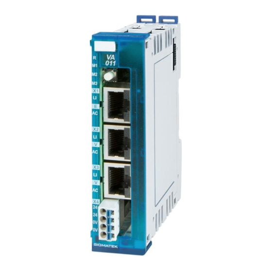
- Page 3 1 VARAN In 1 VARAN Out 1 Ethernet The VA 011 S-DIAS VARAN Analyzer module allows the analy- sis of communication in a real-time Ethernet VARAN bus net- work. The connection is made over a free VARAN port. If no port is available, an existing VARAN bus connection can simply be removed and the VARAN Analyzer inserted.
-
Page 4: Table Of Contents
VA 011 VARAN ANALYZER Contents Introduction ................4 Target Group/Purpose of this Manual ........4 Important Reference Documentation ......... 4 Contents of Delivery ..............4 Basic Safety Guidelines ............5 Symbols Used ................5 Disclaimer ..................6 General Safety Guidelines ............7 Residual Risks ................ - Page 5 VARAN ANALYZER VA 011 Button ..................15 Applicable Connectors ............... 17 Labeling Field ................18 Strain Relief ................19 Wiring from the Control Cabinet to an External VARAN Component .................. 21 Wiring Outside of the Control Cabinet ........22 Shielding for Wiring Within the Control Cabinet ..... 23 Connecting Noise Generating Components ......
-
Page 6: Introduction
Please see our website for our hotline number and business hours. Important Reference Documentation • Design specification VARAN These documents can be downloaded from our website or obtained through SIGMATEK Sup- port. Contents of Delivery 1x VA 011 1x opposing connector This document can be downloaded from our website. -
Page 7: Basic Safety Guidelines
VARAN ANALYZER VA 011 Basic Safety Guidelines Symbols Used The following symbols are used in the operator documentation for warning and danger mes- sages, as well as informational notes: DANGER Identifies an immediate danger with high risk, which will lead to immediate death or serious injury if not avoided. -
Page 8: Disclaimer
Please thoroughly read the corresponding data sheets, operating instructions and this system handbook before handling a product. SIGMATEK GmbH & Co KG is not liable for damages caused through non-compliance with these instructions or applicable regulations. The general and special safety instructions described in the following sec- tions, as well as technical regulations, must therefore be observed. -
Page 9: General Safety Guidelines
Maintain this manual in readable condition and keep it accessible for refer- ence. Operate the unit with devices and accessories approved by SIGMATEK only. CAUTION Handle the device with care and do not drop or let fall. -
Page 10: Residual Risks
Guidelines The panel was constructed in compliance with European Union guidelines. 3.1.1 EU Declaration of Conformity CE Declaration of Conformity The VA 011 conforms to the following European guidelines: • 2014/35/EU Low-voltage guideline • 2014/30/EU “Electromagnetic Compatibility” (EMC guideline) •... -
Page 11: Technical Data
VARAN ANALYZER VA 011 Technical Data Performance Data 1x Gigabit Ethernet 10/100/1000 Interfaces 1x VARAN In (RJ45) (maximum cable length: 100 m) 1x VARAN Out (RJ45) (maximum cable length:100 m) 1x mode button (front) Control Elements Status LEDs 1x RUN... -
Page 12: Environmental Conditions
VA 011 VARAN ANALYZER Environmental Conditions Storage temperature -20 ... +85 °C Environmental temperature 0 ... +55 °C Humidity 0-95 %, non-condensing Installation altitude above sea 0-2000 m without derating level > 2000 m up to a maximum of 5000 m with derating of the maximum envi- ronmental temperature by 0.5 °C per 100 m... -
Page 13: Mechanical Dimensions
VARAN ANALYZER VA 011 Mechanical Dimensions 04.11.2020 Page 11... -
Page 14: Esd Protection
VA 011 VARAN ANALYZER ESD Protection Before any device is connected to or disconnected from the VA 011, the po- tential with ground should be equalized (by touching the control cabinet or ground terminal). Electrostatic loads (through clothing and shoes) can thereby be dissipated. -
Page 15: Connector Layout
VARAN ANALYZER VA 011 Connector Layout The connections of the +24 V supply (X4: pin 1 and pin 2) or the GND supply (X4: pin 3 and pin 4) are internally bridged. To supply the module, only one connection to a +24 V pin (pin 1 or pin 2) and a GND pin (pin 3 or pin 4) is required. -
Page 16: Status Leds
VA 011 VARAN ANALYZER Status LEDs green LIGHTS module operation-ready BLINKS the VARAN Analyzer does not yet have an IP address. Mode LED 1 LIGHTS VARAN PHY held in reset VARAN connection green LIGHTS VARAN Analyzer transparent status no VARAN Out available, the device is then visible as a client in the VARAN network. -
Page 17: Button
VARAN ANALYZER VA 011 Button The operating mode can be changed via the Mode button. With a short press, the Analyzer can be switched to “Streaming Mode”. The active mode is indicated by the Status LED “M2”. If the LED lights green, streaming mode is active. - Page 18 VA 011 VARAN ANALYZER 7.2.1 Connectors 7.2.1.1 X1: Gigabit Ethernet (10/100/1000) Function n.c. = do not use 7.2.1.2 X2, X3: VARAN In, VARAN Out Function Tx+/Rx+ Tx-/Rx- Rx+/Tx+ 4 - 5 n.c. n.c. 7 - 8 Rx-/Tx- More information on the VARAN bus can be found in the VARAN bus speci-...
-
Page 19: Applicable Connectors
VARAN ANALYZER VA 011 Applicable Connectors Connectors: X1 X2 X3 8-pin RJ45 (not included in delivery) X4 Connectors with spring terminals (included in delivery) The spring terminals are suitable for the connection of ultrasonically compressed (ultrasoni- cally welded) strands. Connections:... -
Page 20: Labeling Field
VA 011 VARAN ANALYZER Labeling Field Manufacturer Weidmüller Type MF 10/5 CABUR MC NE WS Article number Weidmüller 1854510000 Compatible printer Weidmüller Type Printjet Advanced 230V Article number Weidmüller 1324380000 Page 18 04.11.2020... -
Page 21: Strain Relief
VARAN ANALYZER VA 011 Strain Relief The VARAN cable must be mounted close to the module (e.g. using a clamp)! No mechanical stress can be applied to the connection! 04.11.2020 Page 19... - Page 22 It is recommended to avoid placing VARAN bus lines parallel to power cables whenever possible. SIGMATEK recommends the use of CAT5e industrial Ethernet bus cables. For the shielding, an S-FTP cable should be used.
-
Page 23: Wiring From The Control Cabinet To An External Varan Component
VARAN ANALYZER VA 011 Wiring from the Control Cabinet to an External VARAN Component If the Ethernet lines are connected from a VARAN component to a VARAN node located outside the control cabinet, the shielding should be placed at the entry point of the control cabinet housing. -
Page 24: Wiring Outside Of The Control Cabinet
VA 011 VARAN ANALYZER Wiring Outside of the Control Cabinet If a VARAN bus line must be connected outside of the control cabinet only, no additional shield support is required. A requirement therefore, is that only IP67 modules and connectors can be used outside the control cabinet. -
Page 25: Shielding For Wiring Within The Control Cabinet
VARAN ANALYZER VA 011 Shielding for Wiring Within the Control Cabinet Sources of strong electromagnetic noise located within the control cabinet (drives, Trans- formers, etc.) can induce interference in a VARAN bus line. Spike voltages are deflected over the metallic housing of a RJ45 connector. Noise is conducted through the control cabinet housing without further action from the electronic components. -
Page 26: Connecting Noise Generating Components
VA 011 VARAN ANALYZER Connecting Noise Generating Components With the connection of power components that generate strong electromagnetic interference, it is also critical to ensure correct shielding. The shielding should be placed before a power element (or group of power elements). -
Page 27: Shielding Between Two Control Cabinets
VARAN ANALYZER VA 011 Shielding Between Two Control Cabinets If two control cabinets must be connected over a VARAN bus, it is recommended that the shielding be located at the entry points of both cabinets. Noise can be thereby prevented from reaching the electronics within the control cabinet. -
Page 28: Transport/Storage
VA 011 VARAN ANALYZER 10 Transport/Storage This device contains sensitive electronics. During transport and storage, high mechanical stress must therefore be avoided. For storage and transport, the same values for humidity and vibration as for operation must be maintained! CAUTION During transport, temperature and humidity fluctuations may occur. -
Page 29: Mounting
VARAN ANALYZER VA 011 11 Mounting The S-DIAS modules are designed for installation into the control cabinet. To mount the mod- ules, a DIN-rail is required. The DIN rail must establish a conductive connection with the back wall of the control cabinet. The individual S-DIAS modules are mounted on the DIN rail as a block and secured with latches. - Page 30 VA 011 VARAN ANALYZER Recommended minimum distances of the S-DIAS modules to the surrounding components or control cabinet wall: a, b, c … distances in mm (inches) Page 28 04.11.2020...
-
Page 31: Maintenance
VARAN ANALYZER VA 011 12 Maintenance WARNING During maintenance as well as servicing, observe the safety instructions from chapter 2. 12.1 Maintenance This product was constructed for low-maintenance operation. 12.2 Repair When sent for repair, the panel should be transported in the original packag- ing if possible. -
Page 32: Disposal
VA 011 VARAN ANALYZER 13 Disposal When disposing of the panel, the national electronic scrap regu- lation must be observed. The panel cannot be discarded with domestic waste. Page 30 04.11.2020... -
Page 33: Application Information
VARAN ANALYZER VA 011 14 Application Information 14.1 IP Settings To assign the VARAN Analyzer a fixed IP address if no DHCP server is available or the Analyzer is connected to the PC/laptop directly, follow the procedure below. 14.1.1 Connecting with the VARAN Analyzer via the VARAN Bus... - Page 34 VA 011 VARAN ANALYZER 14.1.3 Set the IP Address Under Extras > Login, enter the administration password received from support Right-click on the Analyzer and select the menu item “Edit Type Label” In the “Type Label Editor” now opened, select the item “MAC / IP Address”...
-
Page 35: Analysis With The Varan Service Tool
VARAN ANALYZER VA 011 14.2 Analysis with the VARAN Service Tool Connect to the VARAN Analyzer Under Extras, select the VARAN Analyzer tool The description of the VARAN Analyzer function is found under the “?”, Menu item or with the F1 key. -
Page 36: Installation And Analysis With Wireshark
VARAN ANALYZER 14.3 Installation and Analysis with Wireshark With the open-source packet analysis tool Wireshark and the plugin provided by SIGMATEK, the data stream can be analyzed and evaluated with the VA 011. To run an analysis with Wireshark, we recommend connecting the Analyzer output to a ded- icated Ethernet port on the PC/laptop. - Page 37 VARAN ANALYZER VA 011 14.3.2 Analysis with Wireshark Protocol activation Activate the ESL and VARAN proto- cols (Optional) Load the color rules to clearly display the data packets. This can be run under View > Color Rules > Input Next, start a recording at the desired interface.
-
Page 38: Example Application
VA 011 VARAN ANALYZER 14.4 Example Application Page 36 04.11.2020... - Page 39 VARAN ANALYZER VA 011 Documentation Changes Change date Affected Chapter Note page(s) 13.11.2019- 14.3.1 Wireshark Installation Downloadinfo for Wireshark plugin added 04.11.2020 11 Mounting Expansion functional ground connection 04.11.2020 Page 37...
- Page 40 VA 011 VARAN ANALYZER Page 38 04.11.2020...
Need help?
Do you have a question about the VA 011 and is the answer not in the manual?
Questions and answers