Table of Contents
Advertisement
Quick Links
Advertisement
Table of Contents

Related Manuals for Sofraser 9601


Summary of Contents for Sofraser 9601
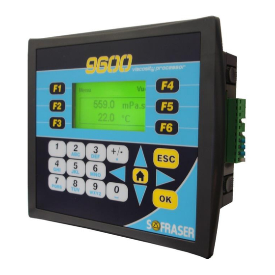
- Page 1 Viscosity Processor 9601 V2.6.1 User Manual Original version Ref.: 237/5...
- Page 3 User Manual 9601 IMPORTANT THE OFFSET ADJUSTMENT IN THE AIR MUST BE THE FIRST TASK COMPLETED. Offset adjustment procedure is detailed in § 5.1 1. CLEAN AND DRY THE SENSOR ROD. 2. BE SURE THE PROCESS IS EMPTY. THE ROD MUST BE VIBRATING IN THE AIR.
-
Page 4: Table Of Contents
User Manual 9601 TABLE OF CONTENT GENERALITIES ................................ 3 Navigation ............................................. 3 Diagnosis ............................................3 Security codes ..........................................3 UTILISATION MODE ..............................4 “Bargraphs” view .......................................... 4 “Compensated viscosity” view ...................................... 4 “Acquisition graph” view ....................................... 4 Information – version ........................................5 Synoptic ............................................ -
Page 5: Generalities
User Manual 9601 1 Generalities Before any use, read carefully the technical manual in order to ensure the good installation of the unit. Navigation : Press on this key enables to return to the previous level. : Press on this key enables to return to the “Bargraphs” view (see § 2.1). -
Page 6: Utilisation Mode
User Manual 9601 2 Utilisation Mode The Utilisation mode enables to visualize viscosity, temperature and density values in various forms. Information related to the sensor identification is gathered in a view accessible since this mode. The Utilisation mode enables the access to the Adaptation mode. -
Page 7: Information - Version
User Manual 9601 The acquisition graph represents viscosity and temperature. One graph represents 120 values and the acquisition time can be set in the “Settings” block. For example: For an acquisition time setting at 30s, the graph will represent an acquisition of 1 hour. -
Page 8: Synoptic
User Manual 9601 Synoptic Navigation between the three views “Bargraphs”, “Compensated viscosity” and “Acquisition graph” is possible by pressing on the key F4. Starting from all these views, pressing on the key F1 enables to reach to the Adaptation mode main menu. -
Page 9: Adaptation Mode
User Manual 9601 3 Adaptation Mode The Adaptation mode enables to adapt parameters, settings and configuration of the processor according to the using conditions. The Menu is accessible, starting from all the Utilisation Mode views, by pressing on the F1 key. -
Page 10: Block "Displays
User Manual 9601 4 Block “Displays” Menu of the block “Displays” Use the arrows to select the function you wish and press “OK”. Choose the Viscosity Unit The security code 3 is needed. To choose the new viscosity unit, it is enough to select it with the arrows and to press “OK”. -
Page 11: Status
User Manual 9601 Select the correction you want to apply using the arrows, for example table C1. If it is indicated “OFF”: the correction is activated and if you press on F3, it will disable the cor- rection. If it is indicated “ON”: the correction is disabled and if you press on F3, it will activate the cor- rection. -
Page 12: Current Outputs Status
Temperature and Density are under their Low thresholds. This is an anomaly so contacts are opened. 4.5.3 Raw data This view is intended for SOFRASER after sales service. In the case of a special calibration, this window can change and display more parameters (2 pages). Ref.: 237/5... -
Page 13: Synoptic Of Block "Display
User Manual 9601 Synoptic of Block “Display” Ref.: 237/5... -
Page 14: Block "Settings
User Manual 9601 5 Block “Settings” Set the offset Air is used as reference fluid in order to adjust the raw signals during the installation. The offset adjustment must be done: At each new installation of the sensor on the process At each observation of the signal drift in the air (§... -
Page 15: Set And Test The Current Outputs
User Manual 9601 Low threshold of temperature alarm Hysteresis of low threshold Example: Alarm 1 = alarm corresponding to the viscosity LOW threshold Alarm 2 = alarm corresponding to the viscosity HIGH threshold Viscosity unit = cP Alarm 1 is activated when the viscosity reaches 10 cP. It stays active as LOW threshold = 15 long as viscosity does not reach the set point 15 cP. -
Page 16: Test The Current Outputs
5.3.2 Test the current outputs Code 1 is needed to access this testing function. This function permits to SOFRASER after-sales service to test current outputs by generating a current. To test an output : For the output you want to test, define a current on this view: Measure the signal on the appropriate connector on the back module of the equipment. -
Page 17: Choose The Method Of Kinematic Viscosity Calculation
It is possible to calculate the kinematic viscosity in 2 ways: Starting from the density measured by a densimeter (in option): When the 9601 processor is delivered with a densimeter, the density input configu- ration (4/20 mA) is the following one: 4 mA →... -
Page 18: Activate The Pt100
User Manual 9601 Example: Acquisition time: A point will be recorded and traced every sec- onds. The graph will represents 2 minutes of acquisition. Activate the Pt100 With Pt100: makes it possible to activate all displays and functions related to the temperature. - Page 19 User Manual 9601 The first filtered viscosity value is calculated (samples number * sampling period) after the starting of the sensor. For example: Samples number = 12 – Sampling period = 100ms Time Ref.: 237/5...
-
Page 20: Synoptic Of Block "Settings
User Manual 9601 Synoptic of Block “Settings” If "Other" is selected Ref.: 237/5... -
Page 21: Block "Parameters
User Manual 9601 6 Block “Parameters” Viscosity corrections This function can be used in two ways: define a correlation define new viscosity unit Correlation: The selection of a viscosity correction makes it possible to correlate the measured viscosity (in cP), starting from the manufacturing calibration data, to the expected viscosity of a product. -
Page 22: Compensation Table
User Manual 9601 The activation of the correction is made in the block “Display” (§ 4.4). NOTES : It is not possible to give a name to these corrections. Compensation table This function enables to read and to modify the temperature compensation table. -
Page 23: Modify The Security Codes
CODE 2 This code gives access to the blocks “Settings” and “Parameters”. CODE 1 Not modifiable and reserved to SOFRASER after-sales service. Not communicated and not modifiable. CODE 0 This code gives access to the parameterized manufacturing data: calibration data and thermal drift table. -
Page 24: Synoptic Of Block "Parameters
User Manual 9601 Synoptic of Block “Parameters” Ref.: 237/5... -
Page 25: Block "Configuration
User Manual 9601 7 Block “Configuration” These data are reserved at the SOFRASER workshop and at the after-sales service. Define the thermal drift table and the calibration data The security code 0 is required to have access to these functions. -
Page 26: Synoptic Of Block "Configuration
User Manual 9601 Synoptic of Block “Configuration” Protected data Code 0 not communicated Ref.: 237/5...
Need help?
Do you have a question about the 9601 and is the answer not in the manual?
Questions and answers