Table of Contents
Advertisement
1012687 Issue 01 – BioAir 2, 3 & 5 Installation and Maintenance Manual
DS1398P
BioAir 2 Gravity Sales Drawing
DS1399P
BioAir 3 Gravity Sales Drawing
DS1400P
BioAir 5 Gravity Sales Drawing
DS1407P
BioAir 2 IPS Sales Drawing
DS1408P
BioAir 3 IPS Sales Drawing
DS1409P
BioAir 5 IPS Sales Drawing
Please request copy of specific sales drawing from our
sales department
1012687
01
BioAir 2, 3 & 5 Manual - Initial Issue
January 2023
1
Advertisement
Table of Contents

Related Manuals for Kingspan Klargester BioAir DS1398P


Summary of Contents for Kingspan Klargester BioAir DS1398P
- Page 1 1012687 Issue 01 – BioAir 2, 3 & 5 Installation and Maintenance Manual DS1398P BioAir 2 Gravity Sales Drawing DS1399P BioAir 3 Gravity Sales Drawing DS1400P BioAir 5 Gravity Sales Drawing DS1407P BioAir 2 IPS Sales Drawing DS1408P BioAir 3 IPS Sales Drawing DS1409P BioAir 5 IPS Sales Drawing Please request copy of specific sales drawing from our...
-
Page 2: Health And Safety
1012687 Issue 01 – BioAir 2, 3 & 5 Installation and Maintenance Manual HEALTH AND SAFETY Please read and follow for your own and others safety You must read these warnings carefully before installing or using the equipment. Please ensure that you have performed a risk assessment before commencing any installation. -
Page 3: Desludging
1012687 Issue 01 – BioAir 2, 3 & 5 Installation and Maintenance Manual DESLUDGING Desludging should be carried out by a licensed waste disposal contractor holding the relevant permits to transport and dispose of sewage sludge. Do not empty the entire reactor and FST, as some biology should remain in the system to continue to work. Final Settlement Tank Reactor Desludging frequency is dependent on the incoming organic load, and therefore site specific. -
Page 4: Table Of Contents
1012687 Issue 01 – BioAir 2, 3 & 5 Installation and Maintenance Manual CONTENTS HEALTH AND SAFETY ....................2 DESLUDGING........................ 3 CONTENTS ........................4 SYSTEM OVERVIEW ...................... 5 ® BioAir CHECKLIST ......................6 SELF HELP ........................7 INTRODUCTION......................8 TECHNICAL DATA ......................8 DESCRIPTION AND PROCESS .................. -
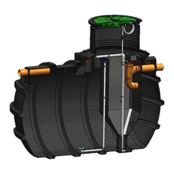
Page 5: System Overview
1012687 Issue 01 – BioAir 2, 3 & 5 Installation and Maintenance Manual SYSTEM OVERVIEW Pictorial representation below indicates basic requirements for a standard system. Cross Section Sludge Return Tank Lid Inlet Outlet Reactor Transfer Port Final Settlement Tank (FST) Diffuser Top View Vent &... -
Page 6: Bioair ® Checklist
1012687 Issue 01 – BioAir 2, 3 & 5 Installation and Maintenance Manual ® BioAir CHECKLIST The delivery paperwork will have 2 no. items listed; check that the Tank Code (Item 1) & Blower Assembly Code (Item 2) are the same as the codes on the units delivered. Example;... -
Page 7: Self Help
Do only flush the 3 P’s (Pee, Poo & Paper) DON’TS Don’t pump feed the plant without seeking advice from Kingspan or installer. Don’t use a waste disposal unit as you will be adding to the biological load, and your system may not be large enough to cope with the waste. -
Page 8: Introduction
1012687 Issue 01 – BioAir 2, 3 & 5 Installation and Maintenance Manual INTRODUCTION Thank you for choosing a Kingspan product. This manual will help you to keep it operating efficiently over a long service life. Please read this manual thoroughly, preferably before installation. -
Page 9: Description And Process
1012687 Issue 01 – BioAir 2, 3 & 5 Installation and Maintenance Manual DESCRIPTION AND PROCESS BioAir systems are designed to accept crude domestic sewage and produce an effluent of suitable quality for discharge to a watercourse or soak-away system, subject to the approval of the appropriate regulatory authority. -
Page 10: Installation
1012687 Issue 01 – BioAir 2, 3 & 5 Installation and Maintenance Manual INSTALLATION Our domestic treatment plants are structurally tested in accordance with EN 12566-3, which specifies structural stability testing for both wet and dry sites using granular backfill 3-8mm. However, in GB & IRE it would be typical for tanks to be installed in concrete due to rising water table, and it can generally be assumed that buoyancy prevention of concrete backfill is more advantageous than the granular backfill materials used in testing. - Page 11 1012687 Issue 01 – BioAir 2, 3 & 5 Installation and Maintenance Manual 1. Excavate Hole & Lay Concrete Bed • Approximate dimensions of units: Water Fill Diameter Unit Height Length Inlet Invert Volume Unit (mm) (mm) (mm) (mm) BioAir 2 455 –...
- Page 12 1012687 Issue 01 – BioAir 2, 3 & 5 Installation and Maintenance Manual 3. Backfill the Tank Unit • The backfilling must start before the base has hardened and must be a single continuous operation, so the tank has a full concrete jacket without joins.
-
Page 13: Electrical Installation
1012687 Issue 01 – BioAir 2, 3 & 5 Installation and Maintenance Manual ELECTRICAL INSTALLATION General Electrical Installation Information Your BioAir will either be supplied with an isolator switch or a control panel for electrical control of the unit. It is imperative that the electrical installation of this equipment is entrusted to a competent qualified electrician working to the latest IEE regulations. - Page 14 1012687 Issue 01 – BioAir 2, 3 & 5 Installation and Maintenance Manual Isolator Wiring Diagram - Gravity System:...
- Page 15 1012687 Issue 01 – BioAir 2, 3 & 5 Installation and Maintenance Manual Isolator Wiring Diagram - IPS System:...
- Page 16 1012687 Issue 01 – BioAir 2, 3 & 5 Installation and Maintenance Manual Control Panel (Premium Specification) Figure 1: 1002510 Lid & Cover Figure 2: Enclosure & Mounting Dimensions...
- Page 17 1012687 Issue 01 – BioAir 2, 3 & 5 Installation and Maintenance Manual Figure 3: Control Panel Wiring (1) Figure 4: DTP Control Panel Wiring (2)
- Page 18 1012687 Issue 01 – BioAir 2, 3 & 5 Installation and Maintenance Manual Blower Blower Unit Control Panel Mains Power Entry Point Diffuser Hose Connection Point Ø19mm Hose Tail Diffuser Hose Entry Point Loss of Pressure Hose General Installation The control panel must not be adjacent to the plant. It can be mounted in the blower housing (supplied with BioAir), wall mounted or fixed to the mounting frame (available separately).
- Page 19 1012687 Issue 01 – BioAir 2, 3 & 5 Installation and Maintenance Manual To prevent damage to the PPFDS hole, a nylon bolt and nut are fitted. If the PPFDS is to be used, replace the bolt with the air inlet bulkhead fitting supplied inside the control unit. A short length of 4mm silicone tubing and a cable tie is also supplied.
- Page 20 1012687 Issue 01 – BioAir 2, 3 & 5 Installation and Maintenance Manual Detailed Operation Once the initialisation is complete the operating screen will appear as follow. Page 1 to 6 can be navigated using ◄ & ► key. Current time will start from 00:00:00 after unit start / restart. Figure 7: Main Screen Page 1 Figure 8: Main Screen Page 2 Page 3 to 6 are like the above, for Motor / Blower &...
- Page 21 1012687 Issue 01 – BioAir 2, 3 & 5 Installation and Maintenance Manual Menu Menu allows timetable entries to be edited, event log to be viewed, date/time, settings, service, battery and setting factory defaults. This menu is intended for use by installation & Service engineers only. The menu is entered by simultaneously pressing then releasing the three buttons ‘◄, ►...
- Page 22 1012687 Issue 01 – BioAir 2, 3 & 5 Installation and Maintenance Manual Settings Setting can be used to amend inputs such as Loss of Rotation or Loss of Pressure, High Level Alarm & Beeper. LOR or LOP & High-Level Alarm will be enabled / disabled during the initialisation Figure 13: Settings Battery This displays the battery charger status.
- Page 23 1012687 Issue 01 – BioAir 2, 3 & 5 Installation and Maintenance Manual Factory Defaults This option allows the control unit to be set back to the defaults as they were when the unit left the factory. The following will be reset with defaults shown in brackets. •...
-
Page 24: Maintenance
1012687 Issue 01 – BioAir 2, 3 & 5 Installation and Maintenance Manual MAINTENANCE Every sewage treatment plant needs regular maintenance as does the upkeep of drainage fields and drains. This is the responsibility of the owner/user. We recommend that plants are maintained by qualified service personnel, however some self-help and an awareness of normal operation is helpful in identification of a larger problem. -
Page 25: Warranty
1012687 Issue 01 – BioAir 2, 3 & 5 Installation and Maintenance Manual WARRANTY Taken from ‘Kingspan’s Terms & Conditions of Sale’ The company will replace or, at its option, properly repair without charge any goods which are found to be defective and which cause failure in normal circumstances of use within a period of twelve months from the date of delivery. -
Page 26: Fault Finding
1012687 Issue 01 – BioAir 2, 3 & 5 Installation and Maintenance Manual FAULT FINDING 1. BLOWER NOT RUNNING Cause Remedy Power cut Do nothing. When power is restored the system will restart automatically Check Mini Circuit Breaker on electrical supply board Power supply RCD (Residual current Device) Isolate the power supply and reset the RCD... -
Page 27: Notice
This notice should be fixed by the owner within the building alerting current and future owners to the maintenance requirement. Please contact Kingspan Water and Energy to arrange a maintenance service or to request replacement operating instructions. Kingspan Water & Energy Service Contact Numbers:... - Page 28 1012687 Issue 01 – BioAir 2, 3 & 5 Installation and Maintenance Manual...
Need help?
Do you have a question about the Klargester BioAir DS1398P and is the answer not in the manual?
Questions and answers