MR MESSKO MPREC Operating Instructions Manual
Pressure relief device
Hide thumbs
Also See for MESSKO MPREC:
- Operating instructions manual (60 pages) ,
- Operating instructions manual (32 pages)
Table of Contents
Advertisement
Quick Links
Advertisement
Table of Contents

Related Manuals for MR MESSKO MPREC


Summary of Contents for MR MESSKO MPREC
- Page 1 Pressure relief device ® ® MESSKO MPREC Operating instructions 5789879/04 EN...
- Page 2 © All rights reserved by Maschinenfabrik Reinhausen Dissemination and reproduction of this document and use and disclosure of its content are strictly prohibited unless expressly permitted. Infringements will result in liability for compensation. All rights reserved in the event of the granting of patents, utility models or designs. The product may have been altered since this document was published.
-
Page 3: Table Of Contents
Table of contents Introduction................ 6 Manufacturer.................. 6 Subject to change without notice ............. 6 Completeness.................. 6 Safekeeping.................. 6 Notation conventions ............... 7 1.5.1 Hazard communication system .............. 7 1.5.2 Information system.................. 8 1.5.3 Instruction system .................. 8 1.5.4 Typographic conventions ................ 9 Safety................... 10 Intended use .................. - Page 4 Table of contents Storage of shipments.............. 23 Further transport ................ 23 Mounting ................ 24 Mounting pressure relief device with standard protective cover .. 27 Mounting pressure relief device with OD protective cover..... 30 Electrically connecting the pressure relief device ...... 35 5.3.1 Connecting cable screw connections............
- Page 5 Table of contents Glossary ................ 68 5789879/04 EN...
-
Page 6: Introduction
Germany Tel.: +49 941 4090-0 E-mail: sales@reinhausen.com Internet: www.reinhausen.com MR Reinhausen customer portal: https://portal.reinhausen.com Further information on the product and copies of this technical file are avail- able from this address if required. 1.2 Subject to change without notice The information contained in this technical file comprises the technical speci- fications approved at the time of printing. -
Page 7: Notation Conventions
1 Introduction 1.5 Notation conventions This section contains an overview of the symbols and textual emphasis used. 1.5.1 Hazard communication system Warnings in this technical file are displayed as follows. 1.5.1.1 Warning relating to section Warnings relating to sections refer to entire chapters or sections, sub-sec- tions or several paragraphs within this technical document. -
Page 8: Information System
1 Introduction Signal word Meaning CAUTION Indicates a hazardous situation which, if not avoided, could result in minor or moderate injury. NOTICE Indicates measures to be taken to prevent damage to property. Table 1: Signal words in warning notices 1.5.2 Information system Information is designed to simplify and improve understanding of particular procedures. -
Page 9: Typographic Conventions
1 Introduction 2. Step 2. ð Result of step (optional). ð Result of action (optional). 1.5.4 Typographic conventions Typographic convention Purpose Example UPPERCASE Operating controls, ON/OFF switches [Brackets] PC keyboard [Ctrl] + [Alt] Bold Software operating con- Press Continue button trols …>…>…... -
Page 10: Safety
2 Safety This technical document contains detailed descriptions on the safe and proper installation, connection, commissioning and monitoring of the prod- uct. ▪ Read this technical document through carefully to familiarize yourself with the product. ▪ This technical document is a part of the product. ▪... -
Page 11: Fundamental Safety Instructions
2 Safety ▪ Use the equipment and special tools supplied solely for the intended pur- pose and in accordance with the specifications of this technical file. ▪ Only operate the product in industrial areas. Observe the notices in this technical document regarding electromagnetic compatibility and the tech- nical data. - Page 12 2 Safety Safety markings Warning signs and safety information plates are safety markings on the product. They are an important aspect of the safety concept. Safety mark- ings are depicted and described in the chapter "Product description". ▪ Observe all safety markings on the product. ▪...
- Page 13 2 Safety 2.3 Personnel qualification The person responsible for assembly, commissioning, operation and inspec- tion must have the following qualifications. Electrically skilled person The electrically skilled person has a technical qualification and therefore has the required knowledge and experience, and is also conversant with the ap- plicable standards and regulations.
- Page 14 2 Safety 2.4 Personal protective equipment Personal protective equipment must be worn during work to minimize risks to health. ▪ Always wear the personal protective equipment required for the job at hand. ▪ Never wear damaged personal protective equipment. ▪ Observe information about personal protective equipment provided in the work area.
-
Page 15: Product Description
3 Product description This chapter contains an overview of the design and function of the product. 3.1 Scope of delivery The following components are included in the delivery: ▪ MPREC® pressure relief device ▪ Technical documents ▪ O-ring 95x3 (only for MPREC® with OD protective cover) ▪... -
Page 16: Design/Versions
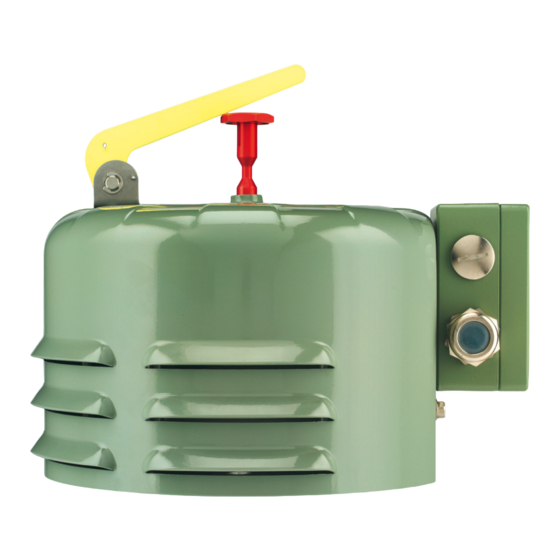
3 Product description 3.3 Design/versions The pressure relief device consists of a device flange with valve, spring as- sembly, signal pin and protective cover; as an option also with 1 or 2 micro- switches and with semaphore. The design and the designation of the key device components are to be found in the following drawings: ▪... - Page 17 3 Product description 3.3.1 Pressure relief device with standard protective cover The following graphic shows the key parts of the pressure relief device: Figure 1: Pressure relief device with standard protective cover 1 Device flange 2 3 housing screws M6x10, wrench size 10 3 Seal (axial) with sealing lip (radial) 4 Ground connection (only in the...
- Page 18 3 Product description 15 Valve plate 16 Vent screw 17 Mounting seal ring Ø200 x Ø178.5 x 4.25 mm [Ø7.87″ x Ø7.03″ x 0.17″] (optional) 3.3.2 Pressure relief device with OD protective cover The OD protective cover has an escape opening for draining the oil in the event of tripping.
-
Page 19: Safety Markings And Nameplate
3 Product description 7 Cable bushing M20x1.5 for cable 8 Ground connection (only in the diameter 8…15 mm (alternatively version with plug) without or with terminal box, with ANSI plug or with Westinghouse plug; see appendices) 9 Vent screw 10 O-ring seal between the device and the protective cover 11 Mounting seal ring Ø200 x Ø178.5 x 4.25 mm [Ø7.87″... - Page 20 3 Product description The nameplate is on the stand plate for the pressure relief device with stan- dard protective cover, and on the flat surface on the cover for the version with the OD protective cover. Figure 4: Nameplate on the MPREC® 5789879/04 EN...
-
Page 21: Packaging, Transport And Storage
4 Packaging, transport and storage 4.1 Purpose The packaging is designed to protect the packaged product during transport, loading, unloading and during periods of storage in such a way that no detri- mental changes occur. The packaging must protect the goods against per- mitted transport stresses such as vibration, knocks and moisture (rain, snow, condensation). - Page 22 4 Packaging, transport and storage Every delivered shipment must be checked for the following by the recipient before acceptance (acknowledgment of receipt): ▪ Completeness based on the delivery slip ▪ External damage of any kind. The checks must take place after unloading, when the box or transport con- tainer can be accessed from all sides.
-
Page 23: Storage Of Shipments
4 Packaging, transport and storage 4.5 Storage of shipments When selecting and setting up the storage location, ensure the following: ▪ Store the product and accessories in the original packaging until installa- tion. ▪ Protect stored goods against moisture (rain, flooding, water from melting snow and ice), dirt, pests such as rats, mice, termites etc. -
Page 24: Mounting
5 Mounting This chapter describes how to mount and connect the device correctly. The pressure relief device is mounted on a device flange on the transformer tank or on-load tap-changer. Note the connection diagrams provided. DANGER Electric shock! Risk of fatal injury due to electrical voltage. Always observe the following safety regulations when working in or on electri- cal equipment. - Page 25 5 Mounting Figure 5: Safety marking: Risk of injury due to spring assembly 1 Counter bearing for spring assem- 2 Safety marking 3 6x counter bearing fixing screws NOTICE Property damage! The function of the device will be impaired due to drying. As a result, the transformer will no longer be protected against impermissible pressure in- creases.
- Page 26 5 Mounting When mounting the standard version vertically, the stand plate [►Section 5.1, Page 27] must face either to the left or right. When mounting the OD version, the oil escape opening [►Section 3.3.2, Page 18] must face down- wards in order to ensure complete drainage of the oil in the event of tripping. Figure 6: Possible mounting positions There must be a clearance of at least 100 mm above or in front of the de- vice, and at least 170 mm with a semaphore.
-
Page 27: Mounting Pressure Relief Device With Standard Protective Cover
5 Mounting 5.1 Mounting pressure relief device with standard protective cover To be able to mount the device, you must open it. Only close it again after it is mounted. Figure 7: Mounting pressure relief device with standard protective cover 1 3 hexagon screws M6x10, wrench 2 Ground connection (only with plug size 10 connection) - Page 28 5 Mounting Opening the device Prepare for mounting the device as follows: 1. To remove the protective cover, pull out the signal pin (5) and screw off the signal pin cap (6) using 2 open-ended wrenches, wrench size 12 and 2. Unscrew the 2 screws (1), wrench size 10, on the stand plate, and the screw, wrench size 10, on the opposite side of the protective cover.
- Page 29 5 Mounting Closing the device After mounting, proceed as follows: 1. If the device is equipped with micro-switches for remote transmission of the signals, first connect these micro-switches; see Electrically connecting the pressure relief device [►Section 5.3, Page 35]. 2. Place the protective cover onto the pressure relief device so that the drill holes for the fixing screws in the protective cover are aligned with the cor- responding threaded holes in the device.
-
Page 30: Mounting Pressure Relief Device With Od Protective Cover
5 Mounting 5.2 Mounting pressure relief device with OD protective cover To be able to mount the device, you must open it. Only close it again after it is mounted. Figure 9: Mounting pressure relief device with OD protective cover 1 4 housing screws M8x100, wrench 2 Protective cover size 13 3 Signal pin, wrench size 12... - Page 31 5 Mounting Mounting the device The dimensions and connection data for mounting are specified in the ap- pendix. 1. Place the mounting seal ring (delivered as an option) under the device. 2. Mount the device onto the counter flange on the transformer / on-load tap- changer by inserting 6 screws M12 or 1/2″...
- Page 32 5 Mounting NOTICE! Protect the o-ring seal between the device and the protective cover; therefore, during all intermediate steps, only position the protective cover lightly and do not press down. Figure 11: Protecting the o-ring seal 3. Lower the protective cover parallel to the device flange and place it lightly on the spring assembly, without pressing the protective cover over the o- ring.
- Page 33 5 Mounting 4. Insert the 4 housing screws into the intended holes and turn the protective cover gently around its axis until the screws engage in the threads in the counter bearing. NOTICE! Do not tilt or jam the protective cover. Tighten the 4 screws slightly crosswise several times to prevent the protective cover from tilting or jamming while it is being lowered.
- Page 34 5 Mounting Mounting the oil drainage unit Figure 14: Mounting the oil drainage unit 1 3 hexagon screws M12x40 with 2 Counter flange of the drainage unit spring washers and washers (sup- plied) 3 Plastic cap as transport lock 4 O-ring 95x3 (supplied) 1.
-
Page 35: Electrically Connecting The Pressure Relief Device
5 Mounting Establishing operational readiness 1. Screw the signal pin cap onto the signal pin using 2 open-ended wrenches, wrench size 12 and 32, with max. torque = 8 Nm. Figure 15: Mounting the signal pin 2. Push the signal pin into the device as far as it will go. 3. -
Page 36: Connecting Cable Screw Connections
5 Mounting Connecting the micro-switches (optional) There are a variety of versions for connecting the optionally installed micro- switches: ▪ Cable screw connections [►Section 5.3.1, Page 36] ▪ Terminal box [►Section 5.3.2, Page 38] ▪ Plug (ANSI or Westinghouse) [►Section 5.3.3, Page 39] Each micro-switch is designed as an electrically isolated normally open and normally closed contact. - Page 37 5 Mounting Figure 17: Connecting micro-switches in the pressure relief device with OD protective cover 1 Micro-switch 1 2 Micro-switch 2 (if not installed, the outer cable screw connection is re- placed with a dummy plug) ► Open standard protective cover [►Section 5.1, Page 27]. ð...
-
Page 38: Connecting The Cable To The Terminal Box
5 Mounting 6. First tighten the inner cable screw connection hand-tight, and then the outer cable screw connection, and ensure that the cables and braided leads remain loose and without tension, and that they are not twisted. 7. Tighten all cable screw connections with max. torque = 5.0 Nm. 8. -
Page 39: Connecting The Plug Connector (Ansi Or Westinghouse)
5 Mounting 5. Close the cable screw connection with max. torque = 6.7 Nm. 6. If used, proceed in the same way for the second cable screw connection. 7. If only one of the two available cable screw connections are used, replace the second cable screw connection with a dummy plug to ensure the IP degree of protection. - Page 40 5 Mounting 3. Lay the socket connection cable between the device and control box and connect the braided leads in the control box in accordance with the pin as- signment. Figure 19: Pin assignment of the ANSI socket connection cable in plan view 1 1 Micro-switch 2 2 Micro-switches Wire colors of the...
- Page 41 5 Mounting Figure 20: Pin assignment of the Westinghouse socket connection cable in plan view 1 1 Micro-switch 2 2 Micro-switches Wire colors of the Pin 1: black Pin 1: red Pin 2: white supplied cable: Pin 4: green Pin 5: blue Pin 4: black Pin 6: white Pin 6: orange...
-
Page 42: Commissioning
6 Commissioning Check that the pressure relief device is functioning correctly before commis- sioning the transformer/on-load tap-changer. You will find a description of the function test in the following. A case where one micro-switch of the pressure relief device is wired to the tripping circuit of the circuit breaker that de-energizes the transformer in the event of an error is used as an example. - Page 43 6 Commissioning 13. If the fire extinguishing unit was deactivated prior to the test, recommis- sion it in accordance with the manufacturer's operating instructions. ð Once this function test has been performed, the transformer / on-load tap- changer can be commissioned. 5789879/04 EN...
-
Page 44: Operation
7 Operation The following section describes how you can monitor and restore the operat- ing state of the device. 7.1 Pressure relief device operating state The operating state of the pressure relief device can be determined exter- nally from the position of the signal pin and from the position of the sema- phore (optional): Figure 21: Operating positions of the signal pin and the semaphore (optional) 1 Operation... -
Page 45: Venting The Pressure Relief Device
7 Operation If the pressure relief device has tripped, the signal pin remains in the alarm position even when the pressure in the transformer / on-load tap-changer has normalized again. If the micro-switches inside the housing are con- nected, a signal is sent simultaneously to the control room. ►... - Page 46 7 Operation 2. Remove the protective cover of the pressure relief device; see Opening the device with standard protective cover [►Section 5.1, Page 27] or with OD protective cover [►Section 5.2, Page 30]. 3. Carefully open the vent screw a few turns using a wrench of wrench size 10 or a screwdriver without unscrewing it completely.
-
Page 47: Maintenance And Inspection
▪ Visual inspection of the flange ▪ Visual inspection of the switches In the event of questions or irregularities, contact the Technical Service de- partment: Maschinenfabrik Reinhausen GmbH MR Service & Complaint Falkensteinstrasse 8 93059 Regensburg, Germany E-mail: service@reinhausen.com or complaint@reinhausen.com 5789879/04 EN... -
Page 48: Fault Elimination
9 Fault elimination This chapter describes how to eliminate simple operating faults. 9.1 Testing the tripping circuit and reason for tripping If the signal pin is in the operation position, the pressure relief device has not tripped. If a micro-switch has, nevertheless, issued a signal, the error can lie in the tripping circuit. -
Page 49: Disposal
10 Disposal Observe the national disposal regulations in the country of use. 10.1 SVHC information in accordance with the REACH regulation This product complies with the provisions of European Regulation 1907/2006/EC dated December 18, 2006 on the Registration, Evaluation, Authorization and Restriction of Chemicals (REACH). The following components of the product contain >... -
Page 50: Technical Data
11 Technical data Operating conditions Location of use Indoors and outdoors; tropic-proof Ambient air temperature -50 °C...+80 °C (mechanical version only) -40 °C...+80 °C (version with micro-switches) Operating temperature -40 °C...+80 °C Insulating fluid tempera- -30 °C...+120 °C ture Storage temperature -50 °C...+80 °C Degree of protection IP66 in accordance with IEC 60529 (terminal box, cable screw connections, mi- cro-switches) - Page 51 11 Technical data Materials Springs Spring steel in accordance with EN 10270-1 SH, com- pression springs with configuration-specific parts paint- ing (in German: KTL) for identification and as corrosion protection Signal pin Seawater-proof aluminum; anodized Red for standard sealing lip (NBR); blue for Viton Vent screw Self-securing;...
- Page 52 11 Technical data Dimensions Connection cable length 1,219 mm [48″]; 1,829 mm [72″]; 2,134 mm [84″]; for plug variant 2,438 mm [96″]; 3,658 mm [144″]; 4,572 mm [180″]; 5,004 mm [197″]; 5,080 mm [200″]; 6,096 mm [240″]; 7,620 mm [300″]; 9,144 mm [360″]; 10,000 mm [394″]; 11,990 mm [472″]; 15,010 mm [591″]; 20,110 mm [792″] Weight Approx.
- Page 53 11 Technical data Micro-switches Standard contact switch- Max. current 10 A 30 ms ing capacity in accor- 24 V DC … 220 V DC dance with IEC 60076-22-1 Making capacity 130 W L/R < 40 ms Breaking capacity 25 W L/R < 40 ms 230 V AC Making capacity 250 VA cos φ > 0.5 Breaking capacity 60 VA cos φ...
- Page 54 11 Technical data Connection at the terminal box Connection terminals Single-wire: 1…4 mm , AWG 18…12; braided leads with ferrule: 0.5…2.5 mm , AWG 21…14 IP66: M25x1.5 for cable diameters 11...20 mm Offshore version: M25x1.5 for cable diameters 9...17 mm, stainless steel Degree of protection IP66 in accordance with IEC 60529 for enclosed devices Connection at plug Connection cable ANSI socket connection cable AWG 16, or...
-
Page 55: Drawings
12 Drawings 5789879/04 EN... - Page 56 13 / 0.51" O 170 / 6.69" SERIAL NUMBER TRANSFORMER ACCESSORIES DIMENSION IN mm PRESSURE RELIEF DEVICE MPREC SHEET MATERIAL NUMBER EXCEPT AS STANDARD COVER 1 1 / NOTED...
- Page 60 ""...
- Page 61 * + , +&+ ""...
- Page 68 Glossary Ambient air temperature Operating temperature Permissible temperature of the air in the Permissible temperature in the immedi- surroundings of the equipment in opera- ate surroundings of the device during tion on which the device is installed. operation taking ambient influences, for example due to the equipment and in- stallation location, into consideration.
- Page 70 Maschinenfabrik Reinhausen GmbH Falkensteinstrasse 8 93059 Regensburg +49 (0)941 4090-0 sales@reinhausen.com www.reinhausen.com ® ® 5789879/04 EN - MESSKO MPREC F0358704 - 12/22 - Maschinenfabrik Reinhausen GmbH 2022 THE POWER BEHIND POWER.
Need help?
Do you have a question about the MESSKO MPREC and is the answer not in the manual?
Questions and answers