Advertisement
Quick Links
WLA321 and WLA322 Access Points Quick Start
See the complete Wireless LAN Services (WLS) product documentation at
http://www.juniper.net/techpubs/.
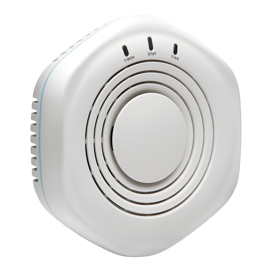
The Juniper Networks WLA321 Wireless LAN Access Point is an indoor, dual-band
access point with one 2.4GHz/5GHz 2x2 IEEE 802.11n radio and two internal antennas.
The Juniper Networks WLA322 Wireless LAN Access Point is an indoor, dual-band
access point with two radios (one 5GHz 2x2 IEEE 802.11n enhanced power radio and
one standard power 2.4GHz radio) and four internal antennas.
Ceiling Installation for WLA321 and WLA322 Access Points
Install WLA321 and WLA322 access points on the ceiling using the mounting bracket
provided with the kit or on a junction box on the wall. The primary installation method for
WLA321 and WLA322s is the ceiling mount. For instructions for purchasing a junction
box wall-mount kit and for installing the access point on the junction box see the WLS
documentation at http://www.juniper.net/techpubs/.
WLA321 and WLA322 Access Point Package
To install and connect the access point, you need:
One ceiling-mount bracket (provided)
Mounting template (provided)
Category 5 straight-through signaling cable with RJ-45 connectors; installed (not
provided)
Box cutter or similar tool to cut ceiling tile (not provided)
(Optional) Security kit, which includes a security tool and a security screw (The kit is
not provided and can be ordered separately.)
Part 1: Install the Access Point
These instructions describe installing the access point on a 9/16-inch or 15/16-inch T
ceiling-tile rail.
1. Select an installation location under a recessed rail in the ceiling.
2. Cut a hole as follows in the ceiling tile for the Category 5 cable:
− Place the mounting template over the area where you will install the access point.
− Use the box cutter or similar tool to cut along the line marking the opening for the
port connectors.
− Remove the mounting template and the material you cut from the ceiling tile.
3. Run the Category 5 cable from the ceiling through the hole in the ceiling tile.
4. Ensure the snaps on the top of the ceiling-mount bracket are open so that the clips
can fully extend to fit around the ceiling rail. The bracket is shipped in an open
position so that it is ready to be clipped over a ceiling rail.
5. If the bracket is closed, open the snaps by pressing in and up with your thumbs on
both sides of the snaps on the bottom of the bracket until it is fully open.
6. With the bracket clips fully extended, align the clips with the rail and hook the clips
around the top sides of the rail. Push in on the sides of the bracket until the clips lock
over the rail. Listen for a click that indicates that the clips have locked. Be sure the
bracket has locked securely onto the rail by gently pulling down on the bracket before
installing the access point.
7. Grasp the Category 5 cable that extends from the ceiling and plug it into the access
point.
Advertisement

Related Manuals for Juniper WLA322


Summary of Contents for Juniper WLA322
- Page 1 2.4GHz radio) and four internal antennas. Ceiling Installation for WLA321 and WLA322 Access Points Install WLA321 and WLA322 access points on the ceiling using the mounting bracket provided with the kit or on a junction box on the wall. The primary installation method for WLA321 and WLA322s is the ceiling mount.
- Page 2 Juniper Networks, Inc. All other trademarks, service marks, registered trademarks, or registered service marks are the property of their respective owners. Juniper Networks assumes no responsibility for any inaccuracies in this document. Juniper Networks reserves the right to change, modify, transfer, or otherwise revise this publication without notice. Products made or sold by Juniper Networks or components thereof might be covered by one or more of the following patents that are owned by or licensed to Juniper Networks: U.S.