
Subscribe to Our Youtube Channel
Related Manuals for Robur Cascade controller


Summary of Contents for Robur Cascade controller
- Page 1 Installation and use manual Cascade controller for the centralized control of Caldaria systems and their distribution circuits...
- Page 2 Revision: D Code: D-LBR874EN This Installation and use manual has been drawn up and printed by Robur S.p.A.; whole or partial reproduction of this Installation and use manual is prohibited. The original is filed at Robur S.p.A. Any use of this Installation and use manual other than for personal consultation must be previously authorised by Robur S.p.A.
-
Page 3: Table Of Contents
Access to menus and parameters ....p. 13 input, 2 circuits of which 1 mixed ....p. 42 Basic parameter programming ..... p. 13 Complete parameter programming .... p. 15 8 Fault codes ................p. 43 9 Menus and parameters table ......p. 44 Installation and use manual – Cascade controller ODSP039... -
Page 4: Iintroduction
This Installation and use manual contains all the RECIPIENTS information needed to install and configure the This Manual is intended for: Cascade controller ODSP039, which can only be Electrical installers for proper installation of the con- used in conjunction with one or more Caldaria ▶... -
Page 5: Iii.2 Compliance
EN 61000-6-1 "Immunity for residential, commercial surges...). ▶ and light-industrial environments". „ Accidental damages or due to force majeure. EN 61000-6-2 "Immunity for industrial environments". ▶ Installation and use manual – Cascade controller ODSP039... -
Page 6: General Information
General information GENERAL INFORMATION The controller is a programmable digital controller with Cascade management up to a maximum of 8 boilers ▶ a display that allows the centralised management of connected to the same controller, with different pri- Caldaria boilers, up to a maximum of 8 boilers connect- ority logics. -
Page 7: Mounting And Installation
1. Secure the OT/Modbus interface inside the control panel of the boiler, using the screw provided (Figure Figure 3.2 Connection of OT/Modbus interface to boiler board +24V RXIN TXOUT Boiler board OT/Modbus interface ODSP040 Connection cable (supplied) Modbus connection Jumper Installation and use manual – Cascade controller ODSP039... - Page 8 Assembly and installation Figure 3.3 ODSP040 board jumper position for Caldaria 35 and 55.1 Jumper open Jumper closed Figure 3.4 ODSP040 board jumper position for Caldaria 100.2 slave module Jumper open Jumper open For further details refer to the OT/Modbus interface instruction sheet.
-
Page 9: Electrical Hookup
Buffer tank 1 diverter valve for DHW charging separator VMixCR1 0-10 V mixing valve for heating circuit 1 HC2 flow probe (optional OSND010) VMixCR2 Mixing valve for heating circuit 2 HC1 flow probe (optional OSND010) Installation and use manual – Cascade controller ODSP039... - Page 10 Assembly and installation Figure 3.6 Electrical connections to following boilers BO02 (P26 = 2) 9 10 11 5 3 1 QLT BO02 MA BO02 2x16A Connection to the previous boiler of the cascade Connection to the following boiler of the cascade Required components OT/Modbus interface (optional ODSP040, except Caldaria Two-pole magnetothermal breaker...
-
Page 11: Preliminary Operations For Programming
2 (Heating + DHW), it is necessary to set the Modbus addresses (set in parameter P26 of each the parameter P01 of each boiler connected to boiler) have been assigned correctly. See also Paragraph Installation and use manual – Cascade controller ODSP039... -
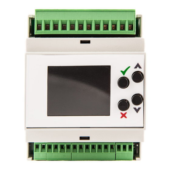
Page 12: Control Panel
Control panel 8 p. 43 . CONTROL PANEL Figure 5.1 Controller control panel Figure 5.2 Relay status bar K1 K2 K3 K4 K1 VMixCR2 valve opening K2 VMixCR2 valve closing K3 HC1 pump K2 KC K3 K4 KC K5 K6 KC K7 K8 K4 HC2 pump K5 CB pump K6 CRC pump... -
Page 13: Menus And Parameters
The default settings are shown in Table 6.1 p. 13 below: on only a few days. 4. When you have finished copying, press to exit. Change temperature levels 1. Use the arrows to select the item "Leve" and Installation and use manual – Cascade controller ODSP039... - Page 14 Menus and parameters The default settings are shown in Table 6.4 p. 14 below: press the key. 2. Use the arrows to select the value for Level Table 6.4 ProgDHW2 default 1 winter, in steps of 0,5 °C. Press the key to save Time slot Time slot start Temperature level Default...
-
Page 15: Complete Parameter Programming
See Paragraph 6.2.1.2 p. 14 . In this menu you set the time programming of the DHW recirculation circuit. 6.3.1.3 ProgDHW1 The default settings are shown in Table 6.1 p. 13 below: See Paragraph 6.2.1.3 p. 14 . Installation and use manual – Cascade controller ODSP039... - Page 16 Menus and parameters Table 6.9 ProgRecirc default inputs (corresponding to the temperature probe readings S1, S2, S3, S4, the status of the external request TA1/TA2 Time slot Time slot start Temperature level Default and any external control signal 0-10 V). 07:00 Lev 0 The special values for probes S1, S2, S3, S4 are: 08:30...
- Page 17 Outdoor temperature limit for heating on -50 ÷ 20 °C ModBoilMAX Maximum modulation degree of the single boiler 10 ÷ 100 % ModBoilON Modulation degree above which the next boiler is switched on 10 ÷ 100 % Installation and use manual – Cascade controller ODSP039...
- Page 18 Menus and parameters Submenu Description Setting Default ModBoilOff Minimum modulation degree below which the previous boiler in the sequence is switched off 0 ÷ 100 % Minimum modulation degree above which the next boiler is switched on or below which the previ- ModBoilMIN 0 ÷...
- Page 19 (BoilerType3, ..., BoilerType8) for all boilers in Setting a value other than 0 activates the activation the cascade system. mode based on minimum modulation (Paragraph Installation and use manual – Cascade controller ODSP039...
- Page 20 Menus and parameters 6.3.6.2 p. 18 ). sequence that is moved to the last position of the next sequence after the time set in the SeqChgTime param- It is recommended not to change the value of eter (Paragraph 6.3.6.16 p. 20 ). this parameter.
- Page 21 6.3.8.2 MinManiTemp The possible values are: See Paragraph 6.2.3.2 p. 15 . 0. NomManiTemp = 0. The antifreeze functions remain 6.3.8.3 UseRedTemp active The parameter defines whether or not to use the value of Installation and use manual – Cascade controller ODSP039...
- Page 22 Menus and parameters 1. NomManiTemp = RedTemp 6.3.8.9 Comp/HExchDeltaT The parameter defines, in the presence of probe S4 6.3.8.4 RedTemp (Paragraph 6.3.8.8 p. 22 ), the temperature difference The parameter sets the NomManiTemp value when the below which the boilers are started up, even though S1 heating circuits are in reduced mode (Lev 0) and any TA/ is satisfied.
- Page 23 6.3.8.13.2 p. 23 ). ceives a voltage of 3 V (minimum value for switching on The value 10 V corresponds to the modulation the system) via the external 0-10 V power request signal. Installation and use manual – Cascade controller ODSP039...
- Page 24 Menus and parameters 6.3.8.16 TempCtrProbe 6.3.9.2 PosVlvMix1 The parameter defines which temperature probe is used The parameter displays the opening percentage of the for control if the ControlType parameter (Paragraph VlvMix1 mixing valve. 6.3.8.14 p. 23 ) is set to value 2. 100% corresponds to open valve, 0% to closed valve.
- Page 25 HC2ActMode, Paragraph 6.3.10.3 p. 25 , to value 1) 6.3.12.8 p. 28 ) when there is a DHW request. 4. not used When set to value 1, heating circuit 2 will always be active Installation and use manual – Cascade controller ODSP039...
- Page 26 Menus and parameters 6.3.11 RoomClimateCurve menu (even when the circuit setpoint is satisfied) and will only be switched off if there is a DHW request, and only if the This menu is not used. parameter DHWPmpSim (Paragraph 6.3.12.8 p. 28 ) is 6.3.12 DHW menu set to value 0.
- Page 27 This operating mode involves feeding the DHW buffer deactivated for DHW buffer tank 2. tank 1 coil through a 3-way diverter valve on the primary circuit and having the SB1 buffer tank probe connected Installation and use manual – Cascade controller ODSP039...
- Page 28 Menus and parameters 6.3.12.3 DHW1Pump to be switched off during DHW charging. The mixed circuit remains active. The parameter displays the status of the CB charging 2. Value to be set when you want both services, DHW pump of the DHW buffer tank 1. production and heating, to be active on both circuits 6.3.12.4 DHW2Pump at the same time.
- Page 29 This menu displays the opening (value 0) or closing (value boiler. 1) status of the external room thermostat request TA2, if 6.3.12.15 InstDHWTemp any. Not used. 6.3.17 WebVisor menu This menu is not used. Installation and use manual – Cascade controller ODSP039...
-
Page 30: System Examples
System examples SYSTEM EXAMPLES 1 BOILER, DHW WITH DIVERTER VALVE, 3 CIRCUITS OF WHICH 2 MIXED Figure 7.1 1 boiler, DHW with diverter valve, 3 circuits of which 2 mixed... -
Page 31: Boiler, Dhw With Delivery, 3 Circuits Of Which 2 Mixed
System examples 1 BOILER, DHW WITH DELIVERY, 3 CIRCUITS OF WHICH 2 MIXED Figure 7.2 1 boiler, DHW with delivery, 3 circuits of which 2 mixed Installation and use manual – Cascade controller ODSP039... -
Page 32: Boiler, Dhw With Diverter Valve, Heat
System examples 1 BOILER, DHW WITH DIVERTER VALVE, HEAT EXCHANGER, 2 CIRCUITS OF WHICH 1 MIXED Figure 7.3 1 boiler, DHW with diverter valve, heat exchanger, 2 circuits of which 1 mixed... -
Page 33: Boiler, Dhw With Delivery, Heat Exchanger, 3 Circuits Of Which 1 Mixed
System examples 1 BOILER, DHW WITH DELIVERY, HEAT EXCHANGER, 3 CIRCUITS OF WHICH 1 MIXED Figure 7.4 1 boiler, DHW with delivery, heat exchanger, 3 circuits of which 1 mixed Installation and use manual – Cascade controller ODSP039... -
Page 34: Boilers, Dhw With Diverter Valve, 2 Circuits Of Which 1 Mixed
System examples 3 BOILERS, DHW WITH DIVERTER VALVE, 2 CIRCUITS OF WHICH 1 MIXED Figure 7.5 3 boilers, DHW with diverter valve, 2 circuits of which 1 mixed... -
Page 35: Boilers, Dhw With Delivery, 3 Circuits Of Which 1 Mixed
System examples 3 BOILERS, DHW WITH DELIVERY, 3 CIRCUITS OF WHICH 1 MIXED Figure 7.6 3 boilers, DHW with delivery, 3 circuits of which 1 mixed Installation and use manual – Cascade controller ODSP039... -
Page 36: Boilers, Dhw With Diverter Valve, Heat
System examples 3 BOILERS, DHW WITH DIVERTER VALVE, HEAT EXCHANGER, 2 CIRCUITS OF WHICH 1 MIXED Figure 7.7 3 boilers, DHW with diverter valve, heat exchanger, 2 circuits of which 1 mixed... - Page 37 System examples 3 BOILERS, DHW WITH DELIVERY, HEAT EXCHANGER, 3 CIRCUITS OF WHICH 2 MIXED Figure 7.8 3 boilers, DHW with delivery, heat exchanger, 3 circuits of which 2 mixed Installation and use manual – Cascade controller ODSP039...
- Page 38 System examples 2 BOILERS, DHW WITH DELIVERY, HEAT EXCHANGER, 3 CIRCUITS OF WHICH 1 MIXED Figure 7.9 2 boilers, DHW with delivery, heat exchanger, 3 circuits of which 1 mixed...
-
Page 39: Boilers, Dhw With 2 Diverter Valves, 2 Circuits Of Which 1 Mixed
System examples 7.10 3 BOILERS, DHW WITH 2 DIVERTER VALVES, 2 CIRCUITS OF WHICH 1 MIXED Figure 7.10 3 boilers, DHW with 2 diverter valves, 2 circuits of which 1 mixed Installation and use manual – Cascade controller ODSP039... -
Page 40: Boilers, Dhw With 2 Deliveries, 4 Circuits Of Which 1 Mixed
System examples 7.11 3 BOILERS, DHW WITH 2 DELIVERIES, 4 CIRCUITS OF WHICH 1 MIXED Figure 7.11 3 boilers, DHW with 2 deliveries, 4 circuits of which 1 mixed... -
Page 41: Boilers, Dhw With Diverter Valve And
System examples 7.12 3 BOILERS, DHW WITH DIVERTER VALVE AND DELIVERY, 3 CIRCUITS OF WHICH 1 MIXED Figure 7.12 3 boilers, DHW with diverter valve and delivery, 3 circuits of which 1 mixed Installation and use manual – Cascade controller ODSP039... -
Page 42: Boilers, Heating Only, 0-10 V External Input, 2 Circuits Of Which 1 Mixed
System examples 7.13 3 BOILERS, HEATING ONLY, 0-10 V EXTERNAL INPUT, 2 CIRCUITS OF WHICH 1 MIXED Figure 7.13 3 boilers, heating only, 0-10 V external input, 2 circuits of which 1 mixed... -
Page 43: Fault Codes
2. Close the TA-TA request contact on the individual boiler. In case of error E32 on the Caldaria 100.2 it will not be possible in any way to activate the boiler until the faulty boards have been replaced. Installation and use manual – Cascade controller ODSP039... -
Page 44: Menus And Parameters Table
Menus and parameters table... - Page 45 Menus and parameters table Installation and use manual – Cascade controller ODSP039...
- Page 46 Menus and parameters table...
- Page 47 Menus and parameters table Installation and use manual – Cascade controller ODSP039...
- Page 48 Menus and parameters table...
- Page 49 Menus and parameters table Installation and use manual – Cascade controller ODSP039...
- Page 52 Robur mission Robur is dedicated to dynamic progression in research, development and promotion of safe, environmentally-friendly, energy-efficiency products, through the commitment and caring of its employees and partners. Robur S.p.A. advanced technologies for air conditioning via Parigi 4/6 24040 Verdellino/Zingonia (BG) Italy +39 035 888111 - F +39 035 884165 www.robur.it robur@robur.it...
Need help?
Do you have a question about the Cascade controller and is the answer not in the manual?
Questions and answers