Table of Contents
Advertisement
Quick Links
Advertisement
Table of Contents

Related Manuals for Robur Direct Digital Controller


Summary of Contents for Robur Direct Digital Controller
-
Page 3: Table Of Contents
GENERAL WARNINGS................................ GENERAL INFORMATION SECTION 2 QUICK GUIDE FOR THE USER................GENERAL CHARACTERISTICS OF THE DIRECT DIGITAL CONTROLLER MAIN SCREEN ........................ 8 ENCODER ................USING THE COOLING/HEATING SERVICE CONTROL MENU............11 ........ BASE AND SEPARABLE DHW SERVICE CONTROL MENU .................... -
Page 4: General Warnings
In the event of failure and/or poor operation of the Direct Digital Controller, do not attempt to repair it under any circumstances; any repair must be carried out solely by a ROBUR Technical Assistance Centre, using only original replacement parts. -
Page 5: General Information
Direct Digital Controller GENERAL INFORMATION The Direct Digital Controller is a device that is applicable as a panel, and which is able to show, on a backlit graphical LCD display of 128x64 pixels, all the status, operating and error conditions of each individual unit to which it is linked. The DDC (Direct Digital Controller) controls water thermostating by controlling the switch-on and switch-off of the units connected to it. - Page 6 RB100/RB200 device present. For RB200 devices a base network ID is set, then the system automatically assigns from this a network ID for each configured service. In the documentation it is also referred to as a CAN ID or, when referred to Robur generators, unit ID or machine ID.
- Page 7 NOTE: The plant ID does not vary between the base and separable/separate plant parts. To indicate on which part of the plant a Robur generator is found we use another parameter to be set on it (group to which the unit belongs); to indicate on which part of the plant a Third Party generator managed via an RB200 device is found, we use a parameter to be set on that device.
- Page 8 Control of plant with third party boilers and/or chillers Using the optional device RB200, the DDC can also control plants which include not only Robur units, but also third party generators (boilers and/or chillers). The RB200 is used to interface these generators through specific input and output signals;...
-
Page 9: Quick Guide For The User
2.1 GENERAL CHARACTERISTICS OF THE DIRECT DIGITAL CONTROLLER The Direct Digital Controller is a device that is applicable as a panel, and which is able to show, on a backlit graphic LCD display of 128x64 pixels, all the status, operating and error conditions of each individual unit to which it is linked. -
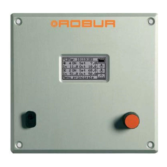
Page 10: Main Screen
Direct Digital Controller 2.2 MAIN SCREEN The Direct Digital Controller is equipped with a backlit LCD graphic display (128x64 pixels), able to display the operating conditions of the plants and each individual unit to which it is linked. The Direct Digital Controller’s display, during normal operation, allows the following parameters to be viewed:... - Page 11 PLANTS CONFIGURED OPERATION ; DHW SYSTEM CONFIGURED OPERATION (4 pipes) COOLING AND/OR HEATING PLANTS ONLY DOMESTIC HOT COOLING AND HEATING PLANTS CONFIGURED FOR ALTERNATING WATER PLANT CONFIGURED CONFIGURED FOR ALTERNATING OPERATION OPERATION Direct Digital Controller fw 4.013 – Ed. 01/2013...
-
Page 12: Using The Encoder
The main user interface for management, programming and control of the DDC is the knob located on the front of the Direct Digital Controller (the encoder). The operations that may be performed with the encoder can be summarised as follows: 1 - Rotate the encoder in a clockwise or anticlockwise direction to position the cursor on the icons to be selected on the display or to modify the value of a numerical field. -
Page 13: Cooling/Heating Service Control Menu
(OFF). The symbol indicates that the button has been disabled and that it is not possible to select it. The switch does not affect the switching on of the units. Direct Digital Controller fw 4.013 – Ed. 01/2013... - Page 14 This means the system regulates the internal room temperature on the basis of chronothermostat programming (for further information see paragraph 3.4.1.2.3 “Chronothermostat”) Direct Digital Controller fw 4.013 – Ed. 01/2013...
- Page 15 GAHP-GS/WS unit. NOTE According to the configuration carried out, some of the buttons may be disabled. (status always ON). For further details, consult Paragraph "On/off command configuration" on page 103. Direct Digital Controller fw 4.013 – Ed. 01/2013...
- Page 16 In order to ensure the real switching off of the plant, switch off also the DHW service(s), as indicated in paragraph 2.5 “BASE AND SEPARABLE DHW SERVICE CONTROL MENU” on page 15. Direct Digital Controller fw 4.013 – Ed. 01/2013...
-
Page 17: Base And Separable Dhw Service Control Menu
In order to ensure the real switching off of the plant, switch off also the heating service, as indicated in paragraph 2.4 “COOLING/HEATING SERVICE CONTROL MENU” on page 11. Direct Digital Controller fw 4.013 – Ed. 01/2013... -
Page 18: Alerts Menu
“MACHINE MANAGEMENT” menu in order to perform an error reset, if necessary. The button allows to access the “INFORMATION MENU” related with the selected unit. Direct Digital Controller fw 4.013 – Ed. 01/2013... -
Page 19: Error Reset
WARNING Error resets for which the message “Contact Technical Assistance” appears must only be carried out by qualified personnel NOTE It is not possible to reset errors on third party machines. Direct Digital Controller fw 4.013 – Ed. 01/2013... -
Page 20: Flame Control Unit Reset
The errors reset can also be done from this menu: position the cursor on then press the knob to carry out the reset of the trouble of the selected unit. It is not possible to reset the flame control unit on third party machines. Direct Digital Controller fw 4.013 – Ed. 01/2013... -
Page 21: Functions Of The Direct Digital Controller
To access the main menu from the initial screen, select . The main menu consists of 5 sections, as indicated in the figure on the right: Functional data. Machine Management User Settings Installation (see Installation” Section) Exit Direct Digital Controller fw 4.013 – Ed. 01/2013... -
Page 22: Functional Data
5 - Select “1/3” or “1/2” to move to the second screen, containing the data of the first module. 6 - If the unit consists of two modules, select “2/3” to move to the third screen, containing the data of the second module. Direct Digital Controller fw 4.013 – Ed. 01/2013... - Page 23 7 - Select “3/3” (or “2/2” in case of unit consisting of one module only) to go back to the first screen 8 - To exit, select When viewing third party boilers or chillers managed via the Robur Box RB200, the first screen shows the generic indication "Third Party Machine" and the serial ID, Hardware and Firmware version of the RB200 device managing the boiler or chiller;...
- Page 24 5 - Turn the knob to select the “Machine status” menu and press the knob to access the menu. 6 - Select to move to the Errors screen: next to the identification number of each unit (ID = machine), the letter E indicates that an error is present. Direct Digital Controller fw 4.013 – Ed. 01/2013...
- Page 25 High generator temperature; 6- Eva Evaporator temperature; 7- TA1 TA2 Auxiliary probes. 8- Mix Air/gas mixture temperature 9- Fumi Temperature of the flue gas 10- GenF Temperature of the generator fins To exit, select Direct Digital Controller fw 4.013 – Ed. 01/2013...
- Page 26 This screen indicates the number of defrosting cycles of the unit (GAHP A-AR plants only). To exit, select Inversions number Reports the number of times the unit has been inverted (GAHP-AR units only). To exit, select Direct Digital Controller fw 4.013 – Ed. 01/2013...
- Page 27 It is not possible to view other data concerning third party machines. 3.2.4 TECHNICAL ASSISTANCE This screen gives information about the nearest Technical Assistance Centre. See Paragraph 4.4.1.12 Technical assistance information regarding the programming of technical assistance information. To exit, select Direct Digital Controller fw 4.013 – Ed. 01/2013...
- Page 28 3 - Turn the knob to select the “Event history” menu, and press the knob to access the menu. 4 - Position the cursor on the vertical scroll arrows (see detail “D” in Figure 6) to scroll through the events, from latest to earliest. 5 - To exit, select Direct Digital Controller fw 4.013 – Ed. 01/2013...
-
Page 29: Units Management
6 - Wait for the operation to be performed. If the operation is successful, the message “OK” appears on the display. 7 - To exit, select NOTE It is not possible to reset the flame control unit on third party machines. Direct Digital Controller fw 4.013 – Ed. 01/2013... - Page 30 6 - Wait for the operation to be performed. If the operation is successful, the message “OK” appears on the display. To exit, select NOTE The reset does not perform a flame control unit reset. NOTE It is not possible to reset errors on third party machines. Direct Digital Controller fw 4.013 – Ed. 01/2013...
- Page 31 This option allows the modification of some parameters that are set on the machine’s built-in electronic board. The Direct Digital Controller communicates with the machine’s electronic board and receives information regarding the parameters set on it. Via the DDC, the operator may modify some of these parameters and transmit them again to the machine’s built-in electronic board.
- Page 32 The option allows the user to restore, via the DDC, the factory settings memorised on the built-in electronic board of the machine. The Direct Digital Controller communicates with the electronic board and receives information regarding the default parameters (factory settings) set on it (warning: the default parameters are read-only, i.e. cannot be modified).
-
Page 33: User Settings
3.4.1.3 External ambient setup 3.4.1.1 Water Setup The following paragraphs describe the operating logic of the Direct Digital Controller to allow the operator to set the water parameters correctly, such as set point temperature, differential, and number of steps. 3.4.1.1.1... - Page 34 The default set point is used when the general water T timer cycles are disabled. Otherwise the set point used at any given moment is that defined in the active water T timer cycle (see Paragraph 3.4.1.1.1.3 - "General water T timer" ). Direct Digital Controller fw 4.013 – Ed. 01/2013...
- Page 35 If the climatic curve is enabled, the water set point is variable and is calculated by the DDC according to the set climatic curve, the external temperature and the requested room temperature. If the climatic curve is disabled, the corresponding default water set point will be used (see paragraph 3.4.1.1.1.1). Direct Digital Controller fw 4.013 – Ed. 01/2013...
- Page 36 11. The cursor moves automatically to for the activation of the timer cycle programmed. Press the knob to enable the timer cycle. The symbol indicates that the timer cycle that has just been programmed has Direct Digital Controller fw 4.013 – Ed. 01/2013...
- Page 37 T timer cycles set on it. If, for example, a 0-10 general water T timer cycle has been set on the Master DDC, and on a Slave DDC a 6-12 partial water T timer cycle, the units managed by the Slave DDC may have ON status only between 6 and10. Direct Digital Controller fw 4.013 – Ed. 01/2013...
- Page 38 . The previous day’s program may be copied for the current day by selecting , or the water T timer cycles required for the new day may be programmed. 13 - To exit, select Direct Digital Controller fw 4.013 – Ed. 01/2013...
- Page 39 It is possible to enable/disable each water T timer cycle programmed without cancelling it by operating on the fields as described below. This programming may be different for each of the seven days of the week. Direct Digital Controller fw 4.013 – Ed. 01/2013...
- Page 40 . The previous day’s program may be copied for the current day by selecting , or the water T timer cycles required for the new day may be programmed. Direct Digital Controller fw 4.013 – Ed. 01/2013...
- Page 41 It is possible to enable/disable each water T timer cycle programmed without cancelling it by operating on the fields as described below. This programming may be different for each of the seven days of the week. Direct Digital Controller fw 4.013 – Ed. 01/2013...
- Page 42 T timer cycle programmed has been disabled. 12. Proceed in the same way, repeating steps 9 – 10 - 11 for the programming of any further timer cycles required. Direct Digital Controller fw 4.013 – Ed. 01/2013...
- Page 43 Programming of differential To set the value or values of the ambient air temperature differential, proceed as follows. 1 - Select from the initial screen to gain access to the main menu. Direct Digital Controller fw 4.013 – Ed. 01/2013...
- Page 44 2 - Select to access the “User settings” menu. 3 - If requested, enter the user password on the numerical keypad that appears on the display; Direct Digital Controller fw 4.013 – Ed. 01/2013...
- Page 45 Indicates that the chronothermostat for heating operation is being programmed. Indicates that the chronothermostat for cooling operation is being programmed. Changes the day for which the chronothermostat is being programmed. Shows the day that is being programmed. Direct Digital Controller fw 4.013 – Ed. 01/2013...
- Page 46 7 - Select “Chronothermostat” from the drop-down menu. 8 - (Two-line hot/cold plants only) Select button “B” to choose the operating mode for which the chronothermostat is to be programmed: for HEATING, for COOLING. Direct Digital Controller fw 4.013 – Ed. 01/2013...
- Page 47 48 periods are to be programmed in the same way as the previous day, use the copy previous day button 15 - When all days of the week have been programmed, exit the menu by selecting Direct Digital Controller fw 4.013 – Ed. 01/2013...
- Page 48 9 - Press the knob to allow the change of the selected value. 10 - Turn the knob to modify the value. 11 - Press the knob to confirm the set value. 12 - To exit, select Direct Digital Controller fw 4.013 – Ed. 01/2013...
- Page 49 9 - Press the knob to allow the change of the selected value. 10 - Turn the knob to modify the differential value. 11 - Press the knob to confirm the set value. 12 - To exit, select Direct Digital Controller fw 4.013 – Ed. 01/2013...
- Page 50 5 - Turn the knob to scroll the cursor downwards until “Date and time” is highlighted and press the knob to access the submenu. 6 - To modify the date and/or time, turn the knob to position the cursor on the value to be modified. Direct Digital Controller fw 4.013 – Ed. 01/2013...
- Page 51 To exit, select 3.4.2.4 Alarm Beeper The Direct Digital Controller is equipped with a beeper that is activated each time an alarm regarding the operation of the units managed occurs. To disable the beep select...
- Page 52 6 - If a user password is present, a numerical keypad appears on the screen. Enter the old password via this keypad and then select to confirm it. 7 - The screen asks for the new password to be entered; enter it and select Direct Digital Controller fw 4.013 – Ed. 01/2013...
- Page 53 If the user password is disabled, it is not necessary to enter it to access the “User settings menu”. If an incorrect password is entered, press Enter. The DDC returns to the previous menu. Direct Digital Controller fw 4.013 – Ed. 01/2013...
-
Page 54: Installation
Connecting the Direct Digital Controller to the units The Direct Digital Controller must be connected to the units via a CAN-BUS cable, to create a data communication network, characterised by a series of “n” nodes as indicated in the examples in Figure 11 or Figure 12. - Page 55 GND= BROWN 200 m Table 1 – EXAMPLES OF CAN-BUS CABLES FOR THE CONNECTION OF THE DIRECT DIGITAL CONTROLLER TO GA and GAHP SERIES UNITS WARNING Diagrams and procedures for connecting the Direct Digital Controller to ROBUR units or to other Robur devices are contained in the specific Installation, Operation, Activation and Maintenance Manuals supplied with the units themselves.
- Page 56 6-pole CAN-BUS connector for connecting the DDC to the units (see detail E in Figure 13). A standard male 9-way connector (RS232 serial port) is located on the front of the Direct Digital Controller for connection to a PC (see Figure 1 on page 7).
- Page 57 (see Figure 14): Create a 155 by 151 mm rectangular opening; Position the Direct Digital Controller over the opening created and mark the 4 points of the holes by which it is to be fixed in place; Make 4 holes of 4 mm in diameter;...
- Page 58 This Direct Digital Controller fw 4.013 – Ed. 01/2013...
-
Page 59: Description Of The Regulation Water Temperature Algorithm And
In this case, the carry out the regulation, the DDC may use: • If the auxiliary boilers are AY modules (Robur), the average temperature read by the machine probes, or dedicated manifold probes, managed by the RB200. •... - Page 60 For category 1 (Robur heat pumps) the value, which is set automatically and cannot be modified, is 6, corresponding to maximum priority. For category 3 (Robur AY boilers) the value set by default is 4, but this can be modified from 0 to 4. For categories 4-5-6-7 (third party boilers) the value set by default is 3, but again this can be modified from 0 to 4.
- Page 61 “would block” the second stage and would switch the first stage off. In the case represented in zone 14, instead, the temperature of the water returns within the differential band before Direct Digital Controller fw 4.013 – Ed. 01/2013...
- Page 62 It goes back to using the values of the first category when all stages of the second are off again. Direct Digital Controller fw 4.013 – Ed. 01/2013...
- Page 63 Direct Digital Controller Figure 16 Direct Digital Controller fw 4.013 – Ed. 01/2013...
- Page 64 (14,4 °F * minutes) (14,4 °F * minutes) the calculation is made when exiting the configuration panel Table 1 – REGULATION PARAMETER DEFAULT VALUESHEATING OPERATION (categories 1 and 3) Direct Digital Controller fw 4.013 – Ed. 01/2013...
- Page 65 Only for categories 4, 5, 6 and 7, for third party boilers, this parameter is also present. For a given category, the parameter is present when assigned to boilers with dedicated water pumps controlled by the Robur system; this has the purpose of establishing the switch off delay for this type of water pump. If more than one...
- Page 66 For the conditioning service, the following categories are defined: • Category 1 The cold modules of all current Robur heat pumps and chillers are assigned to this category. • Categories 2 and 3 These categories are reserved for future Robur products.
- Page 67 For all categories the switch on priority can be freely set in the complete range between 0 and 6; therefore it is possible to set any switch on order for the Robur and third party units. Please note that it is possible to assign the same switching on priority to several categories;...
-
Page 68: System Installation
4.4.1.1 Setting ID This option allows the user to assign the ID of each Direct Digital Controller in Multi DDC plants. For single DDC plants it is not necessary to assign an ID to the DDC, as in this case the default value of ID=960 is assigned. - Page 69 8 - Enter the new password again and select to confirm. NOTE To disable the installer password, do not enter the new password at points 7 and 8 – instead, simply select Direct Digital Controller fw 4.013 – Ed. 01/2013...
- Page 70 8 - Enter the new password again and select to confirm. NOTE To disable the Assistant’s password, do not enter the new password at steps 7 and 8, but select only Direct Digital Controller fw 4.013 – Ed. 01/2013...
- Page 71 KEY: Unit identification number (network ID). Type of Robur or third party unit, or type of plant part managed by RB100 or RB200 device(s); see Table 5 Function of the unit or plant part; C chilled water production; H hot water production;...
- Page 72 87. and to paragraph 4.4.2.6.10 "Heating/DHW select" on page 119 (if at least one hot unit belonging to the base plant is present). Omitting this step, the caption “CONFIG. INCOMPL.” (configuration incomplete) will be shown on the main screen. Direct Digital Controller fw 4.013 – Ed. 01/2013...
- Page 73 Direct Digital Controller Direct Digital Controller fw 4.013 – Ed. 01/2013...
- Page 74 Unit type Description (code on the display) All types of Robur absorption chillers in the ACF60 series All types of Robur absorption chillers with heat recuperators in the ACF60-HR ACF-HR series Robur 35 kW boilers in the AY119 series AY120...
- Page 75 Units belonging to different groups (Base Group and Separable Group) cannot be configured on a Slave DDC On a Slave DDC it is not possible to configure objects managed by RB100 device(s) (plant parts) or RB200 (third party units and plant parts). Direct Digital Controller fw 4.013 – Ed. 01/2013...
- Page 76 7 - A screen appears on which the data described in Figure 18 appears, regarding the DDC on which Multi DDC configuration is being carried out. 8 - Repeat steps 1 to 7 on all other DDCs in the plant. Direct Digital Controller fw 4.013 – Ed. 01/2013...
- Page 77 Groups occurs only on the Master DDC NOTE 4 All objects managed by one or more RB100 (plant parts) or RB200 devices (third party units and plant parts) can only be configured on the plant Master DDC. Direct Digital Controller fw 4.013 – Ed. 01/2013...
- Page 78 8, 9 and 10 to set the category of all third party units of that type. 13 - To exit, select Direct Digital Controller fw 4.013 – Ed. 01/2013...
- Page 79 This option allows to re-initialise the external temperature filter. The values of the external filtered temperature are placed equal to that of the instant external temperature and then the filter is re-activated. Direct Digital Controller fw 4.013 – Ed. 01/2013...
- Page 80 7 - Press the knob: a numerical keypad appears that allows up to 18 characters to be entered. 8 - When the text has been entered, select to confirm and exit. 9 - Repeat the operations described above to enter the other two rows. 10 - To exit, select Direct Digital Controller fw 4.013 – Ed. 01/2013...
- Page 81 Select a Modbus option (typically, Modbus v2.0) in the left or right column, if using a Master Modbus connected respectively to the RS-232 or RS-485 port of the DDC. Robur WISE and Robur Monitor devices require Modbus V2.0 to be set in the left column (RS-232) 4.4.1.14 Modbus address setting...
- Page 82 4 - From the drop-down menu select “DDC”. 5 - Turn the knob to scroll the cursor downwards until “Modbus.Com. Param.” is selected, and press the knob to access the screen. 6 - Select the desired communication parameters. Direct Digital Controller fw 4.013 – Ed. 01/2013...
- Page 83 NOTE This function causes also the loss of machine configuration, Multi DDC configuration and event history. A short message appears on the screen to confirm that the operation has been performed successfully. Direct Digital Controller fw 4.013 – Ed. 01/2013...
- Page 84 4.4.1.18 Software Update (for authorised Technical Assistance Centres only) By connecting to the Personal Computer, this updates the DDC software. The operation may be carried out only by qualified ROBUR personnel or authorised Technical Assistance Centres. 4.4.2 PLANTS Select “Plants” from the drop-down menu, then select the plant. The options available in this menu are: 4.4.2.1...
- Page 85 DDC (see paragraph 2.4 “COOLING/HEATING ” on page 11) or via bus; when a command is sent via bus, the corresponding button will take on the appearance corresponding to the setting made via bus. Direct Digital Controller fw 4.013 – Ed. 01/2013...
- Page 86 (Plant Single Pump or Unit Pumps) and press the knob to make the selection. The symbol indicates that the option has been enabled . 8 - To exit, select Direct Digital Controller fw 4.013 – Ed. 01/2013...
- Page 87 8 - To exit, select NOTE Repeat steps 5 to 8 for the second plant if the DDC is the Master DDC for two plants. In this case the two plants can have different settings. Direct Digital Controller fw 4.013 – Ed. 01/2013...
- Page 88 4.4.2.4 Alarm output setup On the rear of the Direct Digital Controller there is a clean contact to send an external signal if errors have occurred in any machines (see detail “B” Figure 13 on page 54). The DDC allows one of the following options to be set: Disable the signal output in the event of alarm;...
- Page 89 DHW. Then, the set point temperature will be set in the ”User settings” menu, if on the RB100 or RB200 interface the following option is set: “Digital with set point DDC”; or acquired from Robur Box (RB100 or RB200).
- Page 90 6 - Turn the knob to scroll the cursor downward until highlighting “Splitt.Plant Part” and press the knob. 7 - Select “Wat.Differential” from the drop-down menu. Direct Digital Controller fw 4.013 – Ed. 01/2013...
- Page 91 14 - Press the knob to allow the change of the selected value. 15 - Turn the knob until the desired value is displayed. 16 - Press the knob to confirm the set value. Direct Digital Controller fw 4.013 – Ed. 01/2013...
- Page 92 9 - Press the knob to allow the change of the selected value. 10 - Turn the knob until the desired value is displayed. 11 - Press the knob to confirm the set value. Direct Digital Controller fw 4.013 – Ed. 01/2013...
- Page 93 63 and Third party chiller water pump delay on page 65): these parameters are in fact used to set the switch-off delay of water pumps dedicated to third party units, if present and controlled by the Robur system.
- Page 94 9 - Press the knob to allow the change of the selected value. 10 - Turn the knob to modify the value. 11 - Press the knob to confirm the set value. 12 - To exit, select Direct Digital Controller fw 4.013 – Ed. 01/2013...
- Page 95 9 - Press the knob to allow the change of the selected value. 10 - Turn the knob to modify the value. 11 - Press the knob to confirm the set value. Direct Digital Controller fw 4.013 – Ed. 01/2013...
- Page 96 • The presence of an additional temperature probe on the return manifold of the heat pump. • The setting of additional parameters in the regulation parameter settings panel (see 4.4.2.6.4 on page 96). Discuss the applicability of this option with the Robur Pre-Sales Service, before using it. Direct Digital Controller fw 4.013 – Ed. 01/2013...
- Page 97 9 - Press the knob to activate the option. The symbol indicates that the option has been enabled . 10 - Select “Custom” to change the power value (expressed in kW). 11 - To exit, select Direct Digital Controller fw 4.013 – Ed. 01/2013...
- Page 98 10 - If you select “No” the display shows “MANUAL configuration of enable/disable integrals.”; the DDC DOES NOT automatically calculate the two parameters “Enable integral” and “Disable integral”. Use this option if Direct Digital Controller fw 4.013 – Ed. 01/2013...
- Page 99 HEATING, for COOLING and repeat steps 12 -18 to set the parameters for the machine categories in the newly selected operating mode. 20 - To exit, select Direct Digital Controller fw 4.013 – Ed. 01/2013...
- Page 100 63 and Third party chiller water pump delay on page 65): these parameters are in fact used to set the switch-off delay of water pumps dedicated to third party units, if present and controlled by the Robur system.
- Page 101 In the table below, the order in which the plant decides to switch on the units is shown on the basis of the choice made for machine use priority and for operating mode. Cooling GA ACF-HR Type GAHP-GS/WS GA-ACF GAHP-AR Priority(1) Priority(2) Direct Digital Controller fw 4.013 – Ed. 01/2013...
- Page 102 11 - To exit, select NOTE Repeat steps 5 to 9 for the second plant if the DDC is the Master DDC for two plants. Direct Digital Controller fw 4.013 – Ed. 01/2013...
- Page 103 10 - Turn the knob to modify the value. The value can be set from 0 to 600 seconds. 11 - Press the knob to confirm the set value. 12 - To exit, select Direct Digital Controller fw 4.013 – Ed. 01/2013...
- Page 104 This menu item permits to set, for the heating and cooling services, if the unit switching-on requests are controlled only by the DDC, only by the optional Robur BOX (RB100 or RB200) device, or by both (DDC and Robur BOX).
- Page 105 With the exception of the “General switch” consent, all the consents described below affect ONLY the generation of requests by DDC not by Robur Box (RB 100 or RB200). A description of each on/off command is given below, with the aim of aiding the installation technician in selecting the most suitable operating mode (e.g.
- Page 106 For CUSTOM operating mode it is possible to decide whether to enable the command or not: 1 - To enable the command, turn the knob to position the cursor on and press the knob. The Direct Digital Controller fw 4.013 – Ed. 01/2013...
- Page 107 In heating mode, when the external ambient temperature is lower than that set (set point) (for details regarding ExtT mode, see Paragraph 4.5.3.1.5 – “Instructions for operation in ExtT mode”). In cooling mode, when the external ambient temperature is higher than that set. Direct Digital Controller fw 4.013 – Ed. 01/2013...
- Page 108 : the room temperature set-point is always T1 (minimum level of the heating or cooling service) NOTE: continuing to press the knob, the sequence is repeated. NOTE: the climatic curve function is active in all modes stated above. Direct Digital Controller fw 4.013 – Ed. 01/2013...
- Page 109 The consents can be represented as serial switches, as indicated in Figure 20 on page 108; The example represents the Custom operation mode with all the available consents. The BMS On-Off switch is managed Direct Digital Controller fw 4.013 – Ed. 01/2013...
- Page 110 (On-Off) but by varying the temperature on the flow water depending on the external temperature. The Digital Panel foresees various modalities for the management of unit operation as indicated in the table below. Direct Digital Controller fw 4.013 – Ed. 01/2013...
- Page 111 10 - If CUSTOM mode is selected, pass to each individual item ( ), enabling those desired ( ). 11 - To exit, select NOTE If the DDC is the Master of two plants, repeat from 5 to 9 for the second plant Direct Digital Controller fw 4.013 – Ed. 01/2013...
- Page 112 If the slope of the curve selected is not correct, the following cases may occur, to be evaluated during the first working period of the system: Direct Digital Controller fw 4.013 – Ed. 01/2013...
- Page 113 For the example in the previous points, set the value of 1.5, as indicated in Figure 23. NOTE: if no curve passes through the point corresponding to the project temperature, select an intermediate value between those of the curve immediately above or immediately below this point. Direct Digital Controller fw 4.013 – Ed. 01/2013...
- Page 114 19 °C (66,2° F)., set the Offset parameter at a value of 1 °C (1,8 ° F). Water T °F °F Curve for internal environment External environment T T = 20 °C (68° F) – Figure 22 GRAPHICS OF THE “HEATING CURVES” Direct Digital Controller fw 4.013 – Ed. 01/2013...
- Page 115 6 - Turn the knob to scroll the cursor downward until highlighting “Base plant part” and press the knob. 7 - Turn the knob to scroll the cursor downward until highlighting “Cool/Heat. serv. Conf.”. Direct Digital Controller fw 4.013 – Ed. 01/2013...
- Page 116 In cooling mode, the function operates in the same way, clearly with inverted logic with respect to the variations of the outdoor temperature. Direct Digital Controller fw 4.013 – Ed. 01/2013...
- Page 117 If “Limit Max Power” is selected, the three parameters stated in point 10, relative to the hot water production system. • If “Lock boilers” is selected, the outdoor temperature threshold parameter prevents the boilers. 12 - To exit, select Direct Digital Controller fw 4.013 – Ed. 01/2013...
- Page 118 10 - Press the knob to allow the change of the selected value. 11 - Turn the knob to modify the value. 12 - Press the knob to confirm the set value. Direct Digital Controller fw 4.013 – Ed. 01/2013...
- Page 119 In the example for heating systems given above, the minimum set-point temperature of the water will be 40°C (+104° F) even if the climatic curve function should request a lower value. Direct Digital Controller fw 4.013 – Ed. 01/2013...
- Page 120 Master DDC’s chronothermostat. Two operating modes are available: General chronothermostat (Master and slave): in this case the Master DDC’s chronothermostat also controls the commands on the Slave DDCs. Direct Digital Controller fw 4.013 – Ed. 01/2013...
- Page 121 (also contemporary) of hot water for the heating plant and of domestic hot water (DHW). 1 - Select from the initial screen to gain access to the main menu. Direct Digital Controller fw 4.013 – Ed. 01/2013...
- Page 122 10 - Press the knob to allow the change of the selected value. 11 - Turn the knob to modify the value. 12 - Press the knob to confirm the set value. 13 - To exit, select Direct Digital Controller fw 4.013 – Ed. 01/2013...
- Page 123 10 - Press the knob to activate the option. The symbol indicates that the option has been enabled . 11 - To exit, select Direct Digital Controller fw 4.013 – Ed. 01/2013...
- Page 124 11 - To exit, select NOTE A standard 2-line plant cannot make use of this option for the base plant units cannot provide hot water while the plant is switched over to cooling. Direct Digital Controller fw 4.013 – Ed. 01/2013...
- Page 125 Direct Digital Controller PRE-HEATING DHW SUPPLY unit A unit B Figure 24 - SE OF DHW IN COOLING MODE Direct Digital Controller fw 4.013 – Ed. 01/2013...
-
Page 126: Instructions For Ddc-Plant Configuration
To make use of this functionality, the plant shall be provided with an interfacing device called RB100 or RB200 (Robur Box), of which use is made to send to the DDC the switching on/off requests of the configured units. The Direct Digital Controller can communicate with other Direct Digital Controllers of the same type in order to manage plants with more than 16 units. - Page 127 This occurs when units, or modules of units, have been assigned to more than one DDC, linked to the same plant. Direct Digital Controller fw 4.013 – Ed. 01/2013...
- Page 128 In MAN mode, activation and deactivation of the plants, switching from COOLING to HEATING mode and vice versa for two-line plants is performed manually by the user via the Direct Digital Controller that can in addition attend to the management of switch-on and switch-off times, the regulation of the water temperature, the management of timer operating cycles and diagnostics of the units connected.
- Page 129 Before carrying out the activation of the plant, ensure that all operating parameters have been correctly configured (water setpoint, differential, thermostating etc.). Figure 25 illustrates the initial screen for a two-line COOLING/HEATING plant. Direct Digital Controller fw 4.013 – Ed. 01/2013...
- Page 130 COOLING/HEATING switching button - two-line hot/cold plants only ( COOLING, HEATING). If the plant is ON, cooling/heating switching or vice versa lasts 10 minutes. If the plant is OFF (for more than 10 minutes), cooling/heating switching is instantaneous. Direct Digital Controller fw 4.013 – Ed. 01/2013...
- Page 131 Direct Digital Controller (“Plant control” menu). Closing the R - Y and/or R - W contacts on connector D located on the rear of the Direct Digital Controller (see Figure 13 on page 54) determines the activation of the corresponding plant: Closing R-Y activates the cooling plant or the two-line cooling/heating plant, if it is in COOLING mode;...
- Page 132 Chronothermostat button disabled (command disabled in RYWm operating mode). COOLING/HEATING switching button - two-line hot/cold plants only ( COOLING, HEATING). To access the “DHW Plant control” menu, follow the indications given below: Direct Digital Controller fw 4.013 – Ed. 01/2013...
- Page 133 If water T timer cycles are enabled, the plant may only be switched on if the corresponding external contact is closed and if the water T timer is programmed to be on at the time. Figure 26 shows the DDC connection diagram for the RYWm operating mode. EXTERNAL ON/OFF COMMAND. Direct Digital Controller fw 4.013 – Ed. 01/2013...
- Page 134 In RYWa operating mode (two-line hot/cold plants only), selection of COOLING or HEATING operation is managed by the external contacts RY and RW. Closing the contacts R - Y of connector D located on the rear of the Direct Digital Controller (see Figure 13 on page 54) entails: Switching on the plant;...
- Page 135 In RYWa operating mode, the simultaneous closure of the R -Y and R – W contacts is not permitted. If this should happen accidentally, the Direct Digital Controller signals the anomaly “E1005 RY and RW both ON”. Furthermore, in RYWa operating mode, the icon of the “Plant control”...
- Page 136 (symbol of the ON/OFF button in the ON position In case of Multi-DDC plant, it is ON only on the Master DDC; on the Slave DDC(s) it reflects the ON/OFF status set on the Master. Direct Digital Controller fw 4.013 – Ed. 01/2013...
- Page 137 (see example of sensor connection in Figure 28). For two-line hot/cold plants, the selection of COOLING or HEATING mode is carried out manually by the user via the “Plant control” menu on the Digital Controller. Direct Digital Controller fw 4.013 – Ed. 01/2013...
- Page 138 EXAMPLE OF AMBIENT TEMPERATURE SENSOR CONNECTION FOR AmbT MODE T + Diff. + Diff. T - Diff. - Diff. Figure Figure OPERATING PRINCIPLE IN AmbT/ExtT MODE OPERATING PRINCIPLE IN AmbT/ExtT MODE (COOLING) (HEATING) Direct Digital Controller fw 4.013 – Ed. 01/2013...
- Page 139 Main ON/OFF switch. Turn the knob to position the cursor on the button and press the same to activate it (symbol of the ON/OFF button in the ON position Direct Digital Controller fw 4.013 – Ed. 01/2013...
- Page 140 COOLING or HEATING mode are selected manually by the user via the “Plant Control” menu on the Digital Controller using the icon in the menu. Direct Digital Controller fw 4.013 – Ed. 01/2013...
- Page 141 Before switching on the system, ensure that all operating parameters have been correctly configured (temperature set point, thermostating, differential, regulation parameters, alarms etc). To access the “Heating/Cooling Plant control” menu, select from the main menu. Direct Digital Controller fw 4.013 – Ed. 01/2013...
- Page 142 (symbol of the ON/OFF button in the ON position In case of Multi-DDC plant, it is ON only on the Master DDC; on the Slave DDC(s) it reflects the ON/OFF status set on the Master. Direct Digital Controller fw 4.013 – Ed. 01/2013...
- Page 143 EXTERNAL AMBIENT TEMPERATURE SENSOR 1 2 3 4 5 6 Figure 31 – EXAMPLE OF EXTERNAL TEMPERATURE PROBE CONNECTION FOR WCmp MODE Direct Digital Controller fw 4.013 – Ed. 01/2013...
- Page 144 To access the “Heating/Cooling Plant control” menu, select from the main menu. The figure on the right shows the activation screen and the relative buttons and commands that are described below. Direct Digital Controller fw 4.013 – Ed. 01/2013...
- Page 145 (symbol of the ON/OFF button in the ON position In case of Multi-DDC plant, it is ON only on the Master DDC; on the Slave DDC(s) it reflects the ON/OFF status set on the Master. Direct Digital Controller fw 4.013 – Ed. 01/2013...
- Page 146 (also shown in the event history). It is also possible to reset any anomalies or flame arrests, and view and if required edit the machine parameters (authorised Technical Assistance Centres only). Per further information contact ROBUR’s Technical Support Centre (CST).
- Page 147 The number of buttons enabled in the Plant control menu depends on the choice of the consents. To gain access to the “Base and separable DHW service control menu” see page 15. Per further information contact ROBUR’s Technical Support Centre (CST). 4.5.3.2...
-
Page 148: Management And Display Of Warnings And Anomalies
Direct Digital Controller MANAGEMENT AND DISPLAY OF WARNINGS AND ANOMALIES Any operating anomalies of the GA High Efficiency and GAHP units linked to the Direct Digital Controller are signalled and displayed on it via the following: Error menu; Event history (see Paragraph 3.2.5 on page 26);... - Page 149 If the machine has been excluded from the plant via the option in the “Units management” menu. If the unit is performing a defrosting cycle. Option only for GAHP-A and GAHP-AR units. If the unit is off because the limit thermostating temperature value has been reached. Direct Digital Controller fw 4.013 – Ed. 01/2013...
- Page 150 7 - From either of the two screens a machine ID can be selected by turning the knob and pressing it, access is gained to the “Machine Information” menu. 8 - To exit, select Direct Digital Controller fw 4.013 – Ed. 01/2013...
- Page 151 The table below indicates the main anomalies, as well as possible intervention to carry out. CODE ALARM DESCRIPTION W 1000 “New configuration”- New local configuration It is never shown in the “Alerts This warning signals that a new local configuration has been carried out. Direct Digital Controller fw 4.013 – Ed. 01/2013...
- Page 152 E 1008 Master DDC off-line (“Master DDC off-line”) This error is signalled if communication between the Slave DDC and its Master DDC is interrupted. It may only be generated on a Slave DDC. Direct Digital Controller fw 4.013 – Ed. 01/2013...
- Page 153 The trouble occurs, for instance, when the DDC is removed from the plant and it is replaced with a new one, having the same CAN ID and the same configuration but it is switched to the opposite operating mode. Direct Digital Controller fw 4.013 – Ed. 01/2013...
- Page 154 E 1030 OFF: Sep Man Prb Er (Separable Plant Part Manifold Temperature Probe Error) This error is generated if the manifold probe (delivery or return), used to regulate the separable plant part and Direct Digital Controller fw 4.013 – Ed. 01/2013...
- Page 155 The error halts the system (the generators are switched off) if the DDC uses this probe to regulate the plant; in this case it is present together Direct Digital Controller fw 4.013 – Ed. 01/2013...
- Page 156 (i.e. third party modules without water pump control on the base plant part, with the exception of the case below for managing independent water pumps and manifold Direct Digital Controller fw 4.013 – Ed. 01/2013...
- Page 157 To carry out an error reset consult Paragraph 2.7 “Error reset” on Page 17 and Paragraph 2.8 “FLAME CONTROL UNIT RESET” on Page 18. NOTE It is not possible to Reset Errors or Reset the Flame Unit on third party modules. Direct Digital Controller fw 4.013 – Ed. 01/2013...
-
Page 158: General Index
GENERAL WARNINGS GENERAL INFORMATION ..................3 SECTION 2 QUICK GUIDE FOR THE USER GENERAL CHARACTERISTICS OF THE DIRECT DIGITAL CONTROLLER ..7 MAIN SCREEN......................8 USING THE ENCODER................... 10 COOLING/HEATING SERVICE CONTROL MENU ..........11 BASE AND SEPARABLE DHW SERVICE CONTROL MENU ......15 ALERTS MENU...................... - Page 159 Differential......................... 47 3.4.2 PREFERENCES....................... 48 3.4.2.1 Language........................48 3.4.2.2 Date and Time ......................48 3.4.2.3 Temperature Measurement Unit................49 3.4.2.4 Alarm Beeper......................49 3.4.2.5 Display Options......................50 3.4.2.6 User Password Setup....................50 Direct Digital Controller fw 4.013 – Ed. 01/2013...
- Page 160 Water pump mode (Master DDC only) ..............82 4.4.2.3 Partial operation mode (Master DDC of Multi DDC plants only) ......85 4.4.2.4 Alarm output setup ....................86 4.4.2.5 Split plant part......................87 4.4.2.5.1 Heating/DHW Select....................87 Direct Digital Controller fw 4.013 – Ed. 01/2013...
- Page 161 Instructions for operation in MONITOR mode ............144 4.5.3.1.8 Instructions for operation in CUSTOM mode ............144 4.5.3.2 OTHER CONFIGURATIONS ................145 4.5.3.3 WATER PUMP MODE (Master DDC only) ............145 MANAGEMENT AND DISPLAY OF WARNINGS AND ANOMALIES ....146 Direct Digital Controller fw 4.013 – Ed. 01/2013...
- Page 162 Direct Digital Controller With the aim of continuously improving the quality of its products, Robur S.p.A. reserves the right to modify the data and contents of this manual without prior notice. ROBUR S.p.A. Via Parigi, 4/6 24040 Verdellino/Zingonia (Bergamo) Tel. 035- 888111 Fax 035 - 884165 INTERNET: robur@robur.it...
- Page 164 Robur is dedicated to dynamic progression in research, development and promotion of safe, environmentally-friendly, energy-efficiency products, through the commitment and caring of its employees and partners. Robur Mission Robur Spa advanced heating and cooling technologies Via Parigi 4/6 24040 Verdellino/Zingonia (Bg) Italy T +39 035 888111 F +39 035 4821334 www.robur.com...
Need help?
Do you have a question about the Direct Digital Controller and is the answer not in the manual?
Questions and answers