Table of Contents
Advertisement
Quick Links
Advertisement
Table of Contents

Related Manuals for MYiR MYC-YT507H


Summary of Contents for MYiR MYC-YT507H
- Page 1 MYIR-MYC-YT507H-HW-PM-EN_V1.0 MYC-YT507H Product Manual MYIR-MYC-YT507H-HW-PM-EN FILE ID: V1.0 Version: File State: Dana Author: ] Draft [ √ ] Release 2022-04-13 Created: 2022-04-13 Updated: Copyright © MYIR Electronics Limited 2020-2030 all rights reserved. - 1 -...
- Page 2 MYIR-MYC-YT507H-HW-PM-EN_V1.0 History Version Author Participants Date Description V1.0 Dana 20220413 Initial Version - 2 -...
-
Page 3: Table Of Contents
MYIR-MYC-YT507H-HW-PM-EN_V1.0 Contents History ............................- 2 - Contents ........................... - 3 - 1. Overview ................................- 5 - 2. Product Presentation .............................- 8 - 2.1. Chip Resources ......................- 8 - 2.2. Core Board Features ....................- 11 - 2.3. Block Diagram ......................- 12 - 2.4. - Page 4 MYIR-MYC-YT507H-HW-PM-EN_V1.0 6.6. Parallel CSI ........................- 31 - 6.6.1. Pin Description ....................- 31 - 6.7. LVDS ..........................- 32 - 6.7.1. Pin Description ....................- 32 - 6.8. HDMI ..........................- 33 - 6.8.1. Pin Description ....................- 33 - 6.9. TV CVBS Output ......................- 33 - 6.9.1.
-
Page 5: Overview
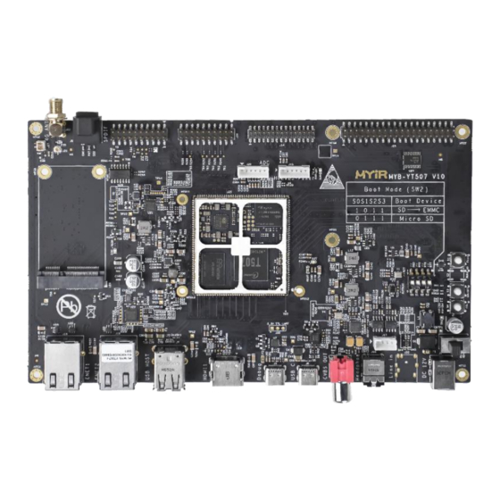
MYC-YT507H core board is based on T507-H processor, has a good software development environment, kernel support open source operating system Linux. MYC-YT507H also has rich interface resources. - Page 6 MYIR-MYC-YT507H-HW-PM-EN_V1.0 Figure 1-1 MYC-YT507H Core board Figure 1-2 MYD-YT507H Kit Top side - 6 -...
- Page 7 MYIR-MYC-YT507H-HW-PM-EN_V1.0 Figure 1-3 MYD-YT507H Kit Bottom side - 7 -...
-
Page 8: Product Presentation
MYIR-MYC-YT507H-HW-PM-EN_V1.0 2. Product Presentation MYC-YT507H core board adopts SMD encapsulation form patch (stamp hole + back pad). There are 4 standard models. They have some differences in storage configuration, temperature and other aspects, customers can choose the appropriate model according to their needs. For the differences between product models, see 2.4. - Page 9 MYIR-MYC-YT507H-HW-PM-EN_V1.0 8-bit Nand flash interface with maximum 80-bit/1KB ECC Video decoder H.265 MP decoder up to 4K@60fps H.264 BL/MP/HP decoder up to 4K@30fps VP9 decoder up to 4K@60fps AVS2 decoder up to 4K@60fps Video Multi-format 1080p@60fps video playback, including VP8,...
- Page 10 MYIR-MYC-YT507H-HW-PM-EN_V1.0 RSA, ECC signature and verification algorithms Supports 160-bit hardware pseudo random number generator(PRNG) with 175-bit seed Supports 256-bit hardware true random number generator(TRNG) Integrated 2K-bit EFUSE for chip ID and security application 3 x USB2.0 Host, l x USB2.0 OTG ...
-
Page 11: Core Board Features
MYIR-MYC-YT507H-HW-PM-EN_V1.0 2.2. Core Board Features Item features CPU series T5 Series CPU model T507-H Processor CPU x4 ARM Cortex -A53 DDR storage LPDDR4 1GB/2GB eMMC EMMC 8GB (Other capacity optional) Core board size 43 x 45 x 3.5 mm (With shielded skeleton) interface type SMD patch,Stamp hole+LGA... -
Page 12: Block Diagram
MYIR-MYC-YT507H-HW-PM-EN_V1.0 2.3. Block Diagram Figure 2-2 Core board block diagram - 12 -... -
Page 13: Core Board Ordering Information
MYIR-MYC-YT507H-HW-PM-EN_V1.0 2.4. Core Board Ordering Information MYC-YT507H core board have 4 models according to the different parameters of core board storage device and operating temperature. Please select the model most suitable for you from the following list. Part No. MYC-YT507H-8E1D-150-I... - Page 14 43 x 45 x 3.5 mm 43 x 45 x 3.5 mm Operating te -40℃ - +85℃ 0℃ - +70℃ mperature Connector Stamp hole+LGA (222 PIN) Stamp hole+LGA (222 PIN) Certification ROHS ROHS Table 2-4 MYC-YT507H core board ordering information 2 - 14 -...
-
Page 15: Pin Description
3. Pin Description 3.1. Pin Out MYC-YT507H core board is welded to the carrier board in the form of SMD patch, and the pin contains a stamp hole and a back pad. For bottom plate packaging design, refer to the instructions in Section 7.2. - Page 16 MYIR-MYC-YT507H-HW-PM-EN_V1.0 Figure 3-2 Module pin at bottom side - 16 -...
-
Page 17: Pin List
MYIR-MYC-YT507H-HW-PM-EN_V1.0 3.2. Pin List The definition of MYC-YT507H core board interface pins is shown in the following table. The pin functions of BSP development package are configured according to "Default functions" in the following table. If you need to change the default pin functions, please modify the relevant driver configuration code;... - Page 18 MYIR-MYC-YT507H-HW-PM-EN_V1.0 LVDS0-CLKN LVDS0-CLKN LVDS0 differential clock - 3.3V RGB multiplexing interface LVDS0-CLKP LVDS0-CLKP LVDS0 differential clock + 3.3V RGB multiplexing interface — LVDS0-D3N LVDS0-D3N LVDS0 differential data 3- 3.3V RGB multiplexing interface LVDS0-D3P LVDS0-D3P LVDS0 differential data 3+ 3.3V RGB multiplexing interface —...
- Page 19 MYIR-MYC-YT507H-HW-PM-EN_V1.0 RGMII-TXCTL RGMII-TXCTL RGMII Send control 3.3V — RGMII-TXCK RGMII-TXCK RGMII Send clock 3.3V — RGMII-TXD0 RGMII-TXD0 RGMII Data sent 0 3.3V RGMII-TXD2 RGMII-TXD2 RGMII Data sent 2 3.3V — SDIO0-D2 SDIO0-D2 SDIO0 Data 2 3.3V SDIO0-CMD SDIO0-CMD SDIO0 command 3.3V...
- Page 20 MYIR-MYC-YT507H-HW-PM-EN_V1.0 HDMI-HPD HDMI-HPD HDMI Hot swap signal 1.8V — HDMI TMDS Differential HTXCP HTXCP clock signal+ HDMI TMDS Differential HTXCN HTXCN clock signal- — HDMI TMDS Differential HTX1P HTX1P data 1+ HDMI TMDS Differential HTX1N HTX1N data 1- — HDMI TMDS Differential...
- Page 21 MYIR-MYC-YT507H-HW-PM-EN_V1.0 UART5-RX UART5-RX UART5 data receive 3.3V UART0-TX UART0-TX Debug UART0 data send 3.3V UART0-RX UART0-RX Debug UART0 data receive 3.3V UART1-TX UART1-TX UART1 data send 3.3V UART1-RX UART1-RX UART1 data receive 3.3V UART1-RTS UART1-RTS UART1 Data request signal 3.3V...
- Page 22 TWI3 clock 3.3V TWI3-SDA TWI3-SDA TWI3 data 3.3V TWI4-SCK TWI4-SCK TWI4 clock 3.3V TWI4-SDA TWI4-SDA TWI4 data 3.3V WREQIN Reserved unused USB2-EXT-IRQ USB2-EXT-IRQ USB2 Wake up interrupt 3.3V DCXO-RFCLK Reserved unused Table 3-1 MYC-YT507H Core board PIN LIST - 22 -...
-
Page 23: Electrical Characteristics
T507-H CPU provides numerous GPIO, these GPIO are grouped so that each group of GPIO can be configured with 3.3V or 1.8V. Users using THE GPIO of MYC-YT507H should be careful that the GPIO level shall not exceed the supply voltage. -
Page 24: Power Consumption
MYIR-MYC-YT507H-HW-PM-EN_V1.0 Table 4-2 T507-H GPIO voltages 4.2. Power Consumption Conditon Voltage(V) Average Current (mA) Power Consumption(W) 4.97 0.994 During boot 4.97 1.998 Full-load stage 0.005 4.97 Mem low-power mode 4.97 0.045 Freeze Low-power mode Table 4-3 Power consumption parameters 4.3. GPIO DC Parameters... -
Page 25: System Start-Up Configuration
The micro SD card is started Table 5-1 BOOT mode configuration 5.2. Special Function Pin The MYC-YT507H core board provides three dedicated pins, namely Reset and ONOFF and FEL. Table 5-2 describes the functions and usage of these functions. function... -
Page 26: Interfaces
MYIR-MYC-YT507H-HW-PM-EN_V1.0 6. Interfaces 6.1. SMHC MYC-YT507H core board leads to two SMHC interfaces, SMHC0 and SMHC1. SMHC0 is commonly used to design micro SD card signals, and SMHC1 can be used to design communication interfaces between modules with SDIO interfaces. -
Page 27: Uart
6.2. UART MYC-YT507H core board has up to 6 serial ports. Due to the pin reuse of the chip, the core board is configured with 4 serial ports by default, among which UART1 has flow control (RTS and CTS signal) function. -
Page 28: Usb
T507-H chip integrates USB2.0 Host controller and USB2.0 OTG controller. The Host controller can provide three USB2.0 Host interfaces, and the OTG controller provides one USB2.0 interface. MYC-YT507H core board brings it all out. Note that the USB2.0 Host interface cannot be used for the OTG interface. -
Page 29: Ethernet
MYIR-MYC-YT507H-HW-PM-EN_V1.0 6.4. Ethernet The MYC-YT507H core board provides two Ethernet MAC controllers. Contains one RMII interface and one RGMII interface (supporting RMII). Ethernet interface design requires proper network PHY chip. 6.4.1. Pin Description Default Signal Description Voltage Comments Function RGMII-MDC... -
Page 30: Mipi Csi
MYIR-MYC-YT507H-HW-PM-EN_V1.0 6.5. MIPI CSI MYC-YT507H provides a 4-lane MIPI CSI camera input interface. MIPI CSI interface supports 8M@30fps or 1080p@25fps. 6.5.1. Pin Description Default Signal Description Voltage Comments Function MCSI-MCLK MCSI-MCLK MIPI CSI Base clock output MCSI-SDA MCSI-SDA MIPI CSI I2C Data... -
Page 31: Parallel Csi
MYIR-MYC-YT507H-HW-PM-EN_V1.0 6.6. Parallel CSI The Parallel CSI interface of MYC-YT507H core board can support up to 5M@15fps or 1080p@30fps video input signal. 6.6.1. Pin Description Default Signal Description Voltage Comments Function NCSI0-SCK NCSI0-SCK Parallel CSI I2C clock 3.3V NCSI0-SDA NCSI0-SDA Parallel CSI I2C data 3.3V... -
Page 32: Lvds
MYIR-MYC-YT507H-HW-PM-EN_V1.0 6.7. LVDS MYC-YT507H core board supports LVDS signal output. MYC-YT507H provides two Single Link LVDS interfaces to support 1366x768@60fps display output. In addition, two Single Link LVDS can form Dual Link LVDS to support higher display resolution 1920x1080@60fps. 6.7.1. -
Page 33: Pin Description
HDMI TMDS Differential data 2+ HTX2N HTX2N HDMI TMDS Differential data 2- Table 6-9 HDMI PIN description 6.9. TV CVBS Output MYC-YT507H core board supports one TV CVBS Output interface and NTSC and PAL modes. 6.9.1. Pin Description Default Signal Description... -
Page 34: Pin Description
SPDIF-OUT SPDIF-OUT Digital audio interface output 3.3V Table 6-11 SPDIF-Out PIN description 6.11. I2S MYC-YT507H core board provides a maximum of three I2S interfaces. Due to pin reuse, one I2S interface is configured by default. 6.11.1. Pin Description Default Signal... -
Page 35: Pin Description
MYIR-MYC-YT507H-HW-PM-EN_V1.0 6.13. GPIO Most of the GPIO pins of MYC-YT507H core board are used as specific functional interfaces, and some GPIO pins are still used as GPIO by default. 6.13.1. Pin Description Default Voltag Signal Description Comments Function IR-RX GPIO EVK Reference design interrupt input 3.3V... -
Page 36: Adc
MYIR-MYC-YT507H-HW-PM-EN_V1.0 6.14. ADC MYC-YT507H core board supports GPADC and LRADC. GPADC has a 12-bit resolution, a maximum sampling rate of 1Mhz, and supports a signal input range of 0~1.8V. LRADC supports a maximum resolution of 6 bits and a sampling rate of 2Khz. The corresponding LRADC supports a range of 0~ 1.35v input signals. -
Page 37: Package Information
MYIR-MYC-YT507H-HW-PM-EN_V1.0 7. Package Information 7.1. Package Dimensions Figure 7-1 MYC-YT507H Core board Bottom view Shield cover thickness 1.8mm PCB thickness 1.6mm Figure 7-2 MYC-C8MMX-V2 Core board side view - 37 -... -
Page 38: Carrier Board Pcb Requirements
MYIR-MYC-YT507H-HW-PM-EN_V1.0 7.2. Carrier Board PCB Requirements MYC-YT507H Pad design size has 2 kinds of specifications: oval hole and round hole two ways. Figure 7-4 shows the design reference sizes of the two pads respectively. Figure 7-3 MYC-YT507H Core board PCB encapsulation... -
Page 39: Carrier Board Pcb Requirement
MYIR-MYC-YT507H-HW-PM-EN_V1.0 Figure 7-4 MYC-YT507H carrier board PCB Sealing dimensions MYIR Electronics provides designed PCB packages. Please visit http://d.myirtech.com/MYD- for this information. YT507H/ 7.3. carrier board PCB requirement A) The thickness of PCB is recommended to be at least 1.6mm, and the balance of copper coating should be paid attention to. -
Page 40: Warranty & Technical Support Services
Delivery Time MYIR will always keep a certain stock for its regular products. If your order quantity is less than the amount of inventory, the delivery time would be within three days; if your order quantity is greater than the number of inventory, the delivery time would be always four to six weeks. - Page 41 For any maintenance service, customers should communicate with MYIR to confirm the issue first. MYIR’s support team will judge the failure to see if the goods need to be returned for repair service, we will issue you RMA number for return maintenance service after confirmation.
- Page 42 Products Life Cycle MYIR will always select mainstream chips for our design, thus to ensure at least ten years continuous supply; if meeting some main chip stopping production, we will inform customers in time and assist customers with products updating and upgrading.
Need help?
Do you have a question about the MYC-YT507H and is the answer not in the manual?
Questions and answers