Advertisement
Dieses Symbol steht bei Textstellen, die besonders zu
beachten sind, damit der ordnungsgemäße Einsatz
gewährleistet ist und Gefahren ausgeschlossen wer-
den. Bitte lesen Sie zuerst die Sicherheitshinweise.
8 mm
48 mm
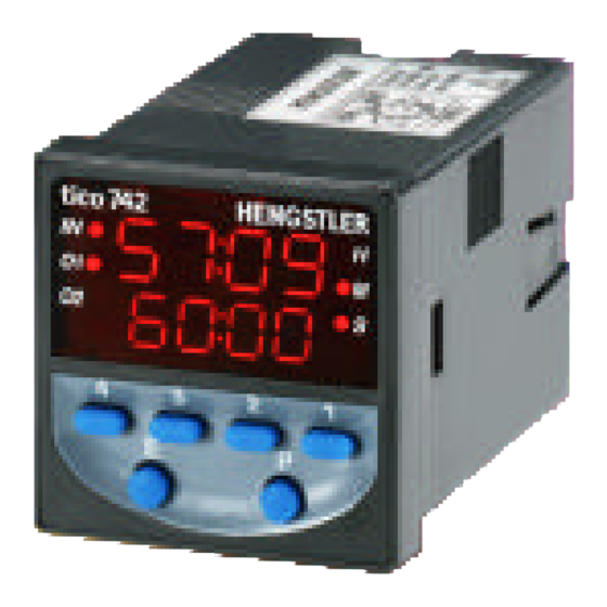
tico 742
4
3
2
1
E
P
S: Stecksockel/ socket
A C Pow er
A C Pow er
Technische Daten 0 742 501/502
Universalspannung 90-240VAC 50/60 Hz oder
24VAC/VDC, Leistungsaufnahme < 10 VA
Anzeige
LED, zweizeilig mit je 4 Ziffern, Indikatoren für Start,
Ausgangsstatus und Zeitbasis
Zeitbereiche
5 Bereiche programmierbar: Stunden, Minuten, Sekunden,
hh:mm, mm:ss; bis zu 9999 Std.
Auflösung
Programmierbar von XXXX bis XX,XX für Stunden, Minuten,
Sekunden, Auflösung herunter bis 0,01 s
Kontakt oder NPN; Anforderungen Kontakt < 1k Ω
Start- /
Reset-Eingang
Anforderungen NPN: VCEO=20V (min), VCE(S) = 1V
(max), IC=50mA (min), ICBO=0.5µA (max)
Signalzeiten
Start Aktivierung: > 20 ms; Deaktivierung > 80ms
Reset Aktivierung: > 20 ms; Deaktivierung > 20ms
Spannungsunterbrechung > 800ms
Kontakte
2 x Wechsler 5A, 120/240VAC oder 30VDC
Ansprechzeit ca. 15ms
Lebensdauer
elektrisch 100.000 Zyklen, mechanisch 10 Mio Zyklen
Montage
Fronttafelmontage mit Spannrahmen oder DIN-Schiene mit
Stecksockel, Fronttafelstärke max. 10 mm
Schutzart
Frontseite IP 65
Temperatur
Betrieb:
0° C bis +55° C
Lagerung: -40° C bis +90°C
Allgemeine
DIN EN 61010 Teil 1; Schutzklasse entsprechend II
Auslegung
Verschmutzungsgrad 2; Überspannungskategorie II
Zubehör
11-poliger Stecksockel 1 740 111
Sach-Nr. 2 742 001; Rev. 1260600MW
Betriebsanleitung
Multifunktions-Zeitrelais mit LED
0 742 501 (90-264 V
0 742 502 (24 V
DC/AC
Digitales elektronisches Zeitrelais. Programmier-
bar sind 6 Betriebsarten und 5 Zeitbereiche, die
von 0,01 s bis 9999 Std. reichen. Alle Einstel-
lungen erfolgen über die Tastatur.
81 mm
66 mm
Warnung: Verbinden Sie niemals eine Spule parallel mit dem Start-Signal. Diese
Verbindung verursacht die ständige Aktivität des Start-Signals. Das gleiche gilt auch
6
für den Reset-Eingang.
7
5
4
8
3
9
Warning: Do not connect a coil in parallel with the start signal. Such a connection will
2
10
cause the start signal to be continuously active. This situation also applies to the
1
11
Reset input.
Operating instructions
- Multifunction Timer with LED
)
0 742 501 (90-264 V
AC
)
0 742 502 (24 V
Electronic Digital Timer with 6 programmable
Operating Modes and 5 time ranges covering 0.01 s
to 9999 hrs. All programming is done via front keys.
This symbol inidcates passages in the text where you have to
pay special attention so as to guarantee correct use and
exclude any risk. Please read the safety and warning hints
first.
45.0
+0.3 mm
Einbauausschnitt
Panel Cutout
Technical Data 0 742 501/502
Power Supply
Display
Time Ranges
Resolution
Start input /
Reset input
Signal times
Contacts
Life
Mounting
Rating
Temperature
General
Accessories
tico 742
AC
)
DC/AC
Start
Out 1
4
3
2
(-)
Universal power supply 90-240 VAC 50/60 Hz or
24 VAC/VDC, power consumption < 10 VA
LED display, 2 lines, 4 digits each line, indicators for the
start signals, output status and time base
5 time ranges can be programmed: Hours, Minutes,
Seconds, hh:mm, mm:ss; up to 9999 hours
Settable for XXXX to XX.XX for Hours, Minutes and
Seconds, resolution down to 0.01 seconds
Dry contact or NPN; Contact requirements < 1kOhm;
NPN requirements: VCEO=20 V (min), VCE(S) = 1 V
(max), IC=50 mA (min), ICBO=0.5 µA (max)
Start activation: > 20 ms; drop out > 80ms
Reset activation: > 20 ms; drop out > 20ms
Power interruption > 800ms
2 x Changeover contact 5A, 120/240 VAC or 30 VDC
Reaction time approx. 15 ms
electrical 100,000 cycles, mechanical 10 million cycles
Front panel mounting with mounting bracket or DIN rail
mounting with socket, panel thicknes max. 10 mm
Front Panel IP 65
Operation: 0°C to 55°C
Storage:
-40° C to +90°C
DIN EN 61010 part 1; Protection according to class II;
Contamination level 2, Overvoltage category II
11 pin socket 1 740 111
)
Reset
6
7
5
Out 2
8
9
10
1
11
Power
(+)
4
1/
Advertisement
Table of Contents

Related Manuals for Hengstler 0 742 501

Summary of Contents for Hengstler 0 742 501
- Page 1 Betriebsanleitung Operating instructions Multifunktions-Zeitrelais mit LED - Multifunction Timer with LED 0 742 501 (90-264 V 0 742 501 (90-264 V 0 742 502 (24 V 0 742 502 (24 V DC/AC DC/AC Digitales elektronisches Zeitrelais. Programmier- Electronic Digital Timer with 6 programmable bar sind 6 Betriebsarten und 5 Zeitbereiche, die operating modes and 5 time ranges covering 0.01 s...
- Page 2 Bedienung Mit den numerischen Tasten 1 bis 4 erhöhen Sie die Each of the number keys 1 to 4 is used to increment jeweilige Ziffenstelle der Zeitvorwahl bzw. eines the value of the corresponding digit of the preset or a Operating Parameterwertes.
- Page 3 Spannrahmen in die Fronttafel einbauen. bracket included in the package. Bestellangaben Ordering Information Multifunktions-Zeitrelais LED (90 - 240 VAC) 0 742 501 Multifunction Timer LED (90 - 240 VAC) 0 742 501 Multifunktions-Zeitrelais LED (24 VAC/VDC) 0 742 502...
- Page 4 Only circuits of the same type are allowed to be connected to the terminals, SELV sources or ELV sources with 1,5 mm² wiring. Vertrieb: Tel. 0 74 24-89 217 (Germany) Hengstler GmbH Tel. 0 74 24-89 572 (Export) Postfach 11 51 Technischer Support: D-78550 Aldingen Tel.
Need help?
Do you have a question about the 0 742 501 and is the answer not in the manual?
Questions and answers