Advertisement
Quick Links
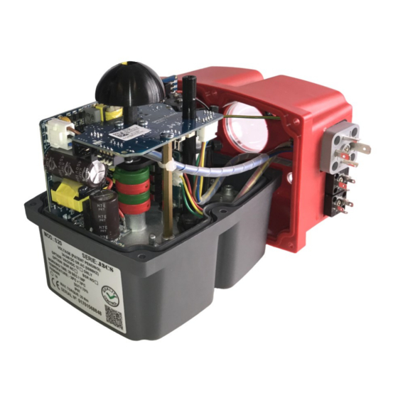
How this JE Series modulating electric valve actuator works
With power permanently connected, movement of the JE actuator is then proportional to an input control signal, typically 4-20mA or
0-10V, usually the output from a process controller. The DPS processor continually compares the physical position of the JE output shaft to
the input signal, and if a difference exists, controls the motor to eliminate the difference. In the JE the output shaft position is measured
very accurately using digital magnetic position sensing technology. An output signal for closed loop control is provided as standard.
WIRING DIAGRAM
Customer supplied
Supplied with actuator
JE Series Digital Positioner Specifications:
Detail
Input/ Output options
Output shaft feedback system
Accuracy, linearity, hysteresis, repeatability
In the interest of product improvement, specifications may change without notice.
JE Series Modulating Electric Actuators
External Power
VAC/VDC
L/+
N/-
①
②
③
Grey Plug
& base
3 x DIN Plugs
Modulating plug &
play kit pre-installed
4-20mA or 0-10V
Input
+
Customer supplied
Control Signal I/O
Output
+
4-20mA /
0-10VDC
③
②
①
Do not connect
Centre Black
Plug & Base
JE Series
0-10V, 1-10V, 0-20mA, 4-20mA
Magnetic, digital
Better than 2%
-
Volt free
Position Confirmation
L/+
N/-
N/-
VAC/VDC
*
*
CLOSED
Customer supplied
*
① ②
③
Right Black
Plug & base
OPEN
Advertisement

Subscribe to Our Youtube Channel
Related Manuals for DynaQuip JE Series


Summary of Contents for DynaQuip JE Series
- Page 1 Modulating plug & play kit pre-installed How this JE Series modulating electric valve actuator works With power permanently connected, movement of the JE actuator is then proportional to an input control signal, typically 4-20mA or 0-10V, usually the output from a process controller. The DPS processor continually compares the physical position of the JE output shaft to the input signal, and if a difference exists, controls the motor to eliminate the difference.
- Page 2 JE Series Modulating Electric Actuators Setting the control signal format In the modulating version of the JE actuator, DIP switches are employed to set the format of the control signal input/ output as follows: CALIBRATION PROCEDURE Push dip switch ‘1’ up, to ‘ON’...
Need help?
Do you have a question about the JE Series and is the answer not in the manual?
Questions and answers