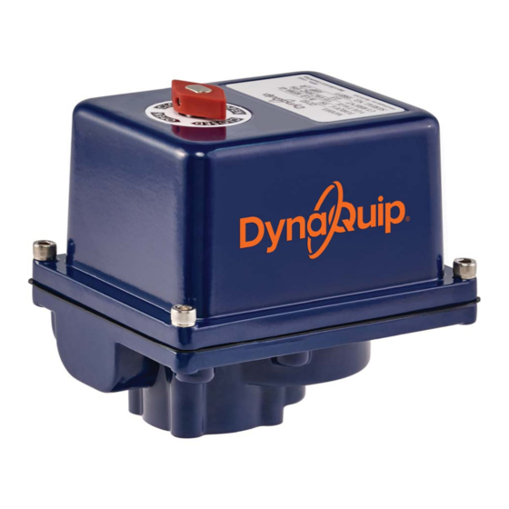
Summary of Contents for DynaQuip DE Series
- Page 1 ENGLISH ESPAÑOL FRANÇAIS DE Series Electric Actuator Installation, Maintenance and Operational Manual To order or for additional information, visit dynaquip.com or call 800-545-3636.
-
Page 2: Electrical Installation
Please read and save these instructions. Read carefully before attempting to assemble, install, operate or maintain the product described. Protect yourself and others by observing all safety information. Failure to comply with instructions could result in personal injury and/or property damage! Retain instructions for future reference. Features Electrical Installation •... - Page 3 SETTING OPEN POSITION 1B SETTING CLOSE POSITION 2B If valve travels too far past open; Manually rotate shaft If valve closed too far; Manually rotate shaft CW past the open position. Follow instructions in 1A for counterclockwise past close position. Follow instructions “Setting Open Position”...
- Page 4 Storage Store in a clean, dry environment and protect from severe temperature changes and vibration. NOTE: After installation it is the customers responsibility to be certain that all set screws, terminal screws, housing bolts and mounting bolts are tight, and limit switches, potentiometers and position transmitters are calibrated to the individual settings required for their specific application.
-
Page 5: Instalación Eléctrica
Coloque la unidad en la posicióncerrada, con giro a pernos de montaje y de adaptador y eje de salida la derecha (CW) (alimentación a los terminales 1 y 3), sean correctas. verifique la alineación. Para ordenar o para obtener información adicional, visite dynaquip.com o llame al 800-545-3636. - Page 6 Coloque la unidad en la posición abierta, con giro a la Se escuchará un chasquido leve. (Para verificar la izquierda (CCW) (alimentación a los terminales 1 y 2), condición con un multímetro: Establezca el multímetro verifique la alineación. en modo “Resistencia” o “Continuidad” . Conecte los conductores a los terminales 3 y 5, gire Si es necesaria la alineación, elimine la alimentación la leva a la derecha hasta que se abra la palanca del...
- Page 7 Diagramas de cableado AVISO: El cableado de campo se muestra únicamente para referencia: no se suministra con el actuador. Diagrama de Cableado del Actuador Electrico Diagrama de Cableado del Actuador Electrico 120 V CA/230 V CA 1 Fase 50-60 Hz 12-24 V CC y 24 V CA 1 Fase Cableado de Campo...
- Page 8 Tabla de Identificación de Problemas PROBLEMA CAUSA/ACCIÓN CORRECTIVA Produce un bajo par • Bajo voltaje o baja corriente. Compruebe que el suministro eléctrico esté dentro de las motor de salida especificaciones indicadas. • Sobrecalentamiento. Vea funcionamiento errático del actuador en párrafos anteriores. Un funcionamiento o •...
-
Page 9: Installation Électrique
Faire fonctionner l’appareil en position fermée, rotation correspondent aux spécifications requises. horaire (bornes 1 et 3 alimentées), vérifier l’alignement. Faire fonctionner l’appareil en position ouverte, rotation antihoraire (bornes 1 et 2 alimentées), vérifier l’alignement. Pour commander ou pour plus d’informations, visitez dynaquip.com ou appelez le 800-545-3636. - Page 10 Si un alignement est requis, couper l’alimentation Un léger déclic doit se faire entendre. (Vérification à électrique vers le servomoteur et suivre les instructions l’aide d’un contrôleur : Placer le contrôleur en mode « de réglage des cames pour l’alignement. Résistance »...
- Page 11 Schémas de câblage REMARQUE : le câblage in-situ et illustré uniquement pour des fins de référence : il n’est pas inclus avec le servomoteur. Schéma de câblage du servomoteur électrique Schéma de câblage du servomoteur électrique 120 V c.a./230 V c.a. monophasé...
- Page 12 Numéro de série Date de l’installation Emplacement Numéro d’étiquette de soupape/ligne Lead Free Made in the USA To order or for additional information, visit dynaquip.com or call 800-545-3636. DynaQuip, 10 Harris Industrial Park, St. Clair, MO 63077 193246.01 REV D...


Need help?
Do you have a question about the DE Series and is the answer not in the manual?
Questions and answers