
Related Manuals for Mega Machine BS-250HAS

Summary of Contents for Mega Machine BS-250HAS
- Page 1 Automatic BANDSAWS BS-250HAS INSTRUCTION MANUAL MEGA MACHINE CO., LTD. DOC NO : BS250HAS-100.U CTRL NO : 06 UPDATE : 1998/7/23 DOC VER : A2...
- Page 2 UP THE MACHINE. The manual contains full instructions on installation, operation, lubrication, maintenance and trouble-shooting. As MEGA MACHINE COMPANY LIMITED is constantly improving the design of its machines, there may be some instance where this book differs somewhat from the machine with which you are concerned.
-
Page 3: Table Of Contents
TABLE OF CONTENTS Item Unit Page Introductory Illustrations Principal parts and outside Dimension Specifications Specifications Standard Accessories Installation Moving and lifting Foundation layout and Set-up 3.2.1 Foundation 3.2.2 Leveling 3.2.3 Cleaning and oiling 3.2.4 Power Source Connection Operation Control Panel Operating preparation Manual Operation Automatic operation... -
Page 4: Introductory Illustrations
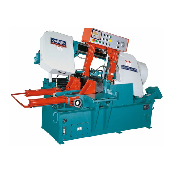
1. INTRODUCTORY ILLUSTRATIONS 1.1 Principal Parts Coolant Pump 10 Hydraulic Blade Tension Set Main Motor 11 Saw Frame Pulley Cover 12 Guide Arm Electric Control Box 13 Guide Arms Slide Stock Tray 14 Quick Approach Rod Chip Conveyance 15 Feed Assembly Lift Cylinder 16 Slide Shaft Water Trough... -
Page 5: Specifications
2 SPECIFICATIONS 2.1 SPECIFICATIONS MODEL BS-250HAS SPECIFICATIONS φ260□300W*180H □280W*250H (Mm) Cutting Capacity φ10□12*7 □11*10 (In) Bundle Cutting (Mm) 200W*140H 8“*5 1/2” (Mm) 34*1.1*3660 Blade Size (In) 1 1/4*0.042*144 (M/Min) 25, 32, 42, 55, 70, 80 Variable Speed 20-80 Blade Speed... -
Page 6: Installation
3. INSTALLATION : 3.1 Moving and Lifting : Unpack your machine carefully , and use a crane or forklift to set it in position. If a crane is used to lift the machine attach the lifting cable carefully to the machine as shown in the fig 2. -
Page 7: Foundation Layout And Set-Up
3.2 Foundation layout and set-up : 3.2.1 Foundation : The foundation should be constructed of reinforced concrete and must be level and flat. After the proper leveling position has been obtained , anchor the machine with anchor bolts. The position of anchor bolts and floor dimensions are shown in fig 4: □... -
Page 8: Leveling
3.2.2 Leveling : The production accuracy of all precision machinery depends on the accuracy which the machine is installed . Manufacturing tolerance of the machine can only be guaranteed if the machine is firmly and properly installed . Once the machine is lowered on the prepared foundation . Machinist levels should be used alternately on the vice slide plates and the work feed table , and adjust the left-and- right and fore-and-aft level of the machine with leveling bolt . -
Page 9: Power Source Connection
3.2.4 Power Source Connection : A. Power Source - This machine is equipped with 3HP main motor 1HP hydraulic motor 1/8HP coolant motor. Connect the power supply cable to the circuit breaker(N.F.B.) terminals. The power supply to your machine should agree with the wring voltage that is indicated on the label attached to the electrical enclosure and main motor. -
Page 10: Operation
4. OPERATION (Type 1) 4.1 Control Panel (1) PNC Control Panel Cutting Piece Counter – This counter is used to preset the number of cuts required on the automatic operation. When the counter reaches the preset number, the machine stops automatically . To activate the counter, preset the counter switch with number at least “1”. - Page 11 Total bar feed needed = length + blade thickness Single step feed = length + K Multiple step feed only needs 1 allowance for blade Thickness ...hence…L + K divided by number of steps Then less K = Digital counter setting length…. (2) PILOT LAMP -- This light will comes on when the power supply is on.
- Page 12 4. OPERATION (Type 2) 4.1 Control Panel PNC Control Panel Cutting Piece Counter – This counter is used to preset the number of cuts required on the automatic operation. When the counter reaches the preset number, the machine stops automatically . To activate the counter, preset the counter switch with number at least “1”.
- Page 13 (2) PILOT LAMP -- This light will comes on when the power supply is on. (3) EMERGENCY STOP -- This switch is used for emergency case to stop the machine only. Turn this switch clockwise makes power source on. When this switch is pressed, all machine's operation stop immediately.
-
Page 14: Operating Preparation
4.2 OPERATING PREPARATION There are several steps will be taken before start the machine. (1) CHOOSE PROPER SAW BLADE : Select the saw blade best suited to the workpiece to be cut, Size and shape of the workpiece , and type of material should all be considered when selecting the saw blade to be used . -
Page 15: Manual Operation
(8) CUTTING LENGTH PRESET : To preset the length of the workpiece to be cut ,use the precise cutting piece counter which is at front leftside of the machine. a. Turn the handle wheel and watch the counter to the length you want to cut. The calibration is 0.10 mm.for example: 400.1 mm b. -
Page 16: Automatic Operation
4.4 AUTOMATIC OPERATION : Having finished all the procedures described above in (2) Operating Preparation ,and with the workpiece to be cut placed in the vise of the machine , but NOT under the saw blade. (1) Turn the AUTO-MANUAL selector to auto. (2) Depress the QUICK APPROACH switch to make the saw frame descend quickly to touch the lower limit position , it will then rise automatically to the freight preset. - Page 17 AMPLIFYING VALVE (1.) THE OUTLINES AND HYDRAULIC CIRCUITS: (2.) SET-UP A. The hydraulic pressure indicated in line <p> should be kept in constant during the whole stroke of the lifting cylinder, i.e. Between the very top and bottom position of the swinging saw frame. we use springs <r>...
- Page 18 B. Re-zeroing knob "a" & "b" on the amplifying valve: For zeroing knob "a", there is a hydraulic pressure gauge as drawing <S> needed, Please plug it onto the outlet on the amplifying valve. Pressure read at line <p> as the primary pressure....pressure <p> Pressure read at amplifying valve as the secondary pressure………...pressure <s>...
-
Page 19: Maintenance
5. Maintenance 5.1 Hydraulic Circuit 5 - 1... - Page 20 5.2 Oiling and Lubricant The operator should be responsible for the proper lubrication of the machine. The grade and quality of lubricant are given in the lubrication chart below : Oil Lubrication chart Lubricating Point Lubricant Quantity Oiling Frequency Blade Tension Device DAPHNE FLUID 32T Twice a year Driving Wheel Bearing...
Need help?
Do you have a question about the BS-250HAS and is the answer not in the manual?
Questions and answers