
Related Manuals for Mega Machine BS-450HAS

Summary of Contents for Mega Machine BS-450HAS
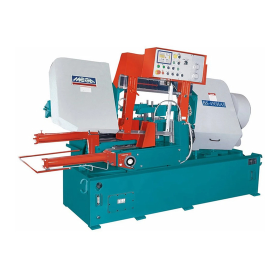
- Page 1 Automatic BANDSAWS BS-450HAS Full Stroke INSTRUCTION MANUAL MEGA MACHINE CO., LTD. BS450HAS 全行程-100.U DOC NO : CTRL NO : UPDATE : 2009/6/17 DOC VER :...
- Page 2 The manual contains full instructions on installation, operation, lubrication, maintenance and trouble-shooting. As MEGA MACHINE COMPANY LIMITED is constantly improving the design of its machines, there may be some instance where this book differs somewhat from the machine with which you are concerned. So, always quote the Serial Number of your machine, when ordering spare parts or in correspondence relating to the machine.
-
Page 3: Table Of Contents
TABLE OF CONTENTS Item Page Unit Introductory Illustrations Principal parts Specifications Specifications Standard Accessories Installation Moving and lifting Foundation layout and Set-up 3.2.1 Foundation 3.2.2 Leveling 3.2.3 Cleaning and oiling 3.2.4 Power Source Connection Operation Control Panel Operating preparation Manual Operation Automatic operation Special Operation Break -In Operation... -
Page 4: Introductory Illustrations
1. INTRODUCTORY ILLUSTRATIONS 1.1 Principal Parts Coolant Pump 10 Hydraulic Blade Tension Set Main Motor 11 Saw Frame Pulley Cover 12 Guide Arm Electric Control Box 13 Guide Arms Slide Stock Tray 14 Quick Approach Rod Chip Conveyance 15 Feed Assembly Lift Cylinder 16 Slide Shaft Water Trough... -
Page 5: Specifications
2 SPECIFICATIONS 2.1 SPECIFICATIONS MODEL BS-450HAS SPECIFICATIONS φ460 □460W*407H (Mm) Cutting Capacity φ18” □18”*16”H (In) (Mm) 360W*255H Bundle Cutting (In) 14“W*10”H (Mm) 38W*1.3t *4880L Blade Size (In) 1 1/2”W *0.05”t *192”L (M/Min) 25,32,42,55,70,80 OPTIONAL 20 – 80 Blade Speed (F/Min) 82,105,138,180,230,260 OPTIONAL 65 –... -
Page 6: Installation
3. INSTALLATION : 3.1 Moving and Lifting : Unpack your machine carefully , and use a crane or forklift to set it in position. If a crane is used to lift the machine attach the lifting cable carefully to the machine as shown in the fig 2. -
Page 7: Foundation Layout And Set-Up
3.2 Foundation layout and set-up: 3.2.1 Foundation: The foundation should be constructed of reinforced concrete and must be level and flat. After the proper leveling position has been obtained , anchor the machine with anchor bolts. The position of anchor bolts and floor dimensions are shown in fig 4: □... -
Page 8: Leveling
3.2.2 Leveling : The production accuracy of all precision machinery depends on the accuracy which the machine is installed . Manufacturing tolerance of the machine can only be guaranteed if the machine is firmly and properly installed . Once the machine is lowered on the prepared foundation . Machinist levels should be used alternately on the vice slide plates and the work feed table , and adjust the left-and- right and fore-and-aft level of the machine with leveling bolt . -
Page 9: Power Source Connection
3.2.4 Power Source Connection : A. Power Source - This machine is equipped with 7.5HP main motor 2HP hydraulic motor 1/8HP coolant motor. Connect the power supply cable to the circuit breaker(N.F.B.) terminals. The power supply to your machine should agree with the wring voltage that is indicated on the label attached to the electrical enclosure and main motor. -
Page 10: Operation
4. OPERATION (Type 1) 4.1 Control Panel (1) PNC Control Panel Cutting Piece Counter – This counter is used to preset the number of cuts required on the automatic operation. When the counter reaches the preset number, the machine stops automatically . To activate the counter, preset the counter switch with number at least “1”. - Page 11 (2) PILOT LAMP -- This light will comes on when the power supply is on. (3) EMERGENCY STOP -- This switch is used for emergency case to stop the machine only. Turn this switch clockwise makes power source on. When this switch is pressed, all machine's operation stop immediately.
- Page 12 (Type 2) 4. OPERATION 4.1 Control Panel (1) PNC Control Panel Cutting Piece Counter – This counter is used to preset the number of cuts required on the automatic operation. When the counter reaches the preset number, the machine stops automatically . To activate the counter, preset the counter switch with number at least “1”.
- Page 13 (2) PILOT LAMP -- This light will comes on when the power supply is on. (3) EMERGENCY STOP -- This switch is used for emergency case to stop the machine only. Turn this switch clockwise makes power source on. When this switch is pressed, all machine's operation stop immediately.
-
Page 14: Operating Preparation
4.2 Operating Preparation (1) Choose Proper Saw Blade : Select the saw blade best suited to the workpiece to be cut, Size and shape of the workpiece , and type of material should all be considered when selecting the saw blade to be used . There is a reference chart in chapter 9 which can help you to select the right saw blade and cutting conditions . -
Page 15: Manual Operation
(6) ADJUST THE POSITION OF THE WIRE BRUSH : a. loosen the lock lever of the wire brush case. b. Manually move the wire brush case so that wire brush just contacts the cutting edge of the saw blade. c. Tighten the lock lever. (7) ADJUST THE FEED RATE : Select suitable feed rate for the workpiece to be cut. -
Page 16: Automatic Operation
*. Before you start to cut the workpiece, you must inspect that..*. The workpiece is well clamped. *. The saw blade is suitable for the material being cut. *. The feed rate is suitable for the material being cut. *. -
Page 17: Break-In Operation
4.6 BREAK-IN OPERATION : When a new blade is used , be sure to first break in the blade before using it for extended operation. Failure to break in the blade will shorten the service lift of the blade ,and result in less than optimum efficiency. -
Page 18: Addition 1 Amplifying Valve
ADDITION 1: Amplifying Valve (1.) The outlines and hydraulic circuits: (2.) SET-UP A. The hydraulic pressure indicated in line <p> should be kept in constant during the whole stroke of the lifting cylinder, i.e. Between the very top and bottom position of the swinging saw frame. we use springs <r>... - Page 19 B. Re-zeroing knob "a" & "b" on the amplifying valve: For zeroing knob "a", there is a hydraulic pressure gauge as drawing <S> needed, Please plug it onto the outlet on the amplifying valve. Pressure read at line <p> as the primary pressure....pressure <p> Pressure read at amplifying valve as the secondary pressure..
-
Page 20: Maintenance
5. Maintenance 5.1 Hydraulic Circuit 5 - 1... - Page 21 5.2 Oiling and Lubricant The operator should be responsible for the proper lubrication of the machine. The grade and quality of lubricant are given in the lubrication chart below : Oil Lubrication chart Lubricating Point Lubricant Quantity Oiling Frequency Blade Tension Device DAPHNE FLUID 32T Twice a year Driving Wheel Bearing...
-
Page 22: Others
5.3 Others VARIABLES WHICH AFFECT BANDSAW BLADE LIFE 1 . The Operator - The operator is the most important variable at any test. He can make or break any test and often has a great deal of influence over whose bandsaw blades are used. He can also be a good source of information on what is going on, competitive situations, relationships with manufacturers or distributors, etc. - Page 23 12. Machine Condition-Whether a machine is old or new, and whether well maintained or not contributes to how well it runs and how long the band last. The better shape a machine is in, the better the bands will run. Poor machines ruin bandsaw blades. 13.
-
Page 24: Trouble Shooting Guide
6. TROUBLE SHOOTING GUIDE The following charts contains some typical troubles along with the probable causes and remedies for each. 6.1 Sawing Problems and Solution Vibration during cutting Failure to cut Short life of saw blade Curved cutting Broken blade Use blade with correct pitch, ○... -
Page 25: Minor Operating Troubles And Remedies
6.2 Minor Operating Troubles and Remedies Symptom Probable Cause Remedy 1. Buttons do not (1) Power disconnected (1) Connect function (2) Circuit protector OFF (2) Turn on (3) Thermal relay activated (3)Push reset button (4) Safety interlocks that is a. Load workpiece a. -
Page 26: Error Information
6.3. Error information The following table contains some typical errors along with the error details and remedies. AH257_ Bandsaws Trouble shooting guide Error name 異常名稱 排除方法 Code Remedy 正常停機 1.Press Blade-ascending button 按鋸帶上升按鈕 Machine stops normally 上升電磁閥異常 1.Eliminate breakdown 1.排除故障原因 Solenoid - ascending frame abnormal 2.Press Blade-ascending button 2.按鋸帶上升按鈕... - Page 27 異常編號 異常名稱 排除方法 Remedy 鋸帶啟動按鈕卡死異常 1.Eliminate breakdown 1.排除故障原因 2.Press Blade-ascending button 2.按鋸帶上升按鈕 Starting blade button jammed 鋸帶下降按鈕卡死異常 1.Eliminate breakdown 1.排除故障原因 2.Press Blade-ascending button 2.按鋸帶上升按鈕 Descending blade button jammed 送料架前進按鈕卡死異常 1.Eliminate breakdown 1.排除故障原因 2.Press Blade-ascending button 2.按鋸帶上升按鈕 Feed-forward button jammed 送料架後退按鈕卡死異常 1.Eliminate breakdown 1.排除故障原因...
-
Page 28: Reference Charts
7. REFERENCE CHARTS 7.1 Standard Cutting Chart Material Blade Pitch Blade Speed Cutting Rate Service Life Sq c ㎡/min Sq c ㎡/PCE JIS code m/min S20C-S50C 50-70 42000-58000 S9CK-S15C 42-60 38500-54000 S53C-S58C 42-60 35000-58000 SS-50 42-60 38500-58000 SS-41 40-55 35000-54000 SM-50 40-55 35000-54000... -
Page 29: Standard Cutting Chart
7.2 Standard Cutting Chart Material AISI Brinell Blade speed Cutting rate code No. hardness Bhn Sq in/min 1108-1111 150-175 220-260 9.0-12.0 1112-1118 125-150 240-270 10.0-14.0 1115-1132 140-165 220-260 9.0-12.0 1137-1151 155-180 180-200 5.0- 8.5 1212-1213 150-175 240-270 10.0-14.0 1008-1013 150-175 220-260 7.0- 9.0 1015-1035... - Page 30 7.3 Standard Cutting Chart Material AISI Brinell blade peed Cutting ate code No. hardness Bhn sq in/min. Stainless Steels 302,304 130-170 80-90 303,303F 150-200 90-100 308,309,310 160-220 60-80 314,317,330 160-220 50-80 316,420 160-220 70-80 321,347 165-200 90-100 410,420F 140-185 100-110 416,430F 155-195 140-150...
Need help?
Do you have a question about the BS-450HAS and is the answer not in the manual?
Questions and answers