Table of Contents
Advertisement
Quick Links
Advertisement
Table of Contents

Related Manuals for vanEssen Diver-Link DN4 Series


Summary of Contents for vanEssen Diver-Link DN4 Series
- Page 1 Diver-Link DN4xx Series Diver-Link Triple DN4xx-3 Series...
- Page 2 Tucker, GA, United States 30083 Tel: +1 520-203-3445 (US West) Tel: +1 678-983-2818 (US East) Internet: www.vanessen.com Support: diver@vanessen.com Copyright © 2020 by Van Essen Instruments B.V. All rights reserved. This document contains proprietary information which is protected by copyright. No part of this document may be photocopied, reproduced, or translated to another language without the prior written consent of Van Essen Instruments B.V.
- Page 3 I hereby declare that the equipment named above has been designed to comply with the relevant sections of the above referenced specifications. The items comply with all applicable Essential Requirements of the Directives. © April 2023 Van Essen Instruments. All rights reserved. www.vanessen.com...
-
Page 4: Table Of Contents
Smart Interface Cable ......................21 DXT Cable ..........................22 DXT Cable Suspension Kit ......................22 TD-Diver ............................ 22 5.10 Baro-Diver ..........................23 5.11 Cera-Diver ..........................23 5.12 Micro-Diver ..........................24 5.13 CTD-Diver ..........................24 © April 2023 Van Essen Instruments. All rights reserved. www.vanessen.com... -
Page 5: Introduction
The Diver-Link connects to a 2G, 3G or 4G/LTE cellular network and transmits the Diver data and the data from its internal barometric datalogger to the Diver-HUB server. © April 2023 Van Essen Instruments. All rights reserved. www.vanessen.com... -
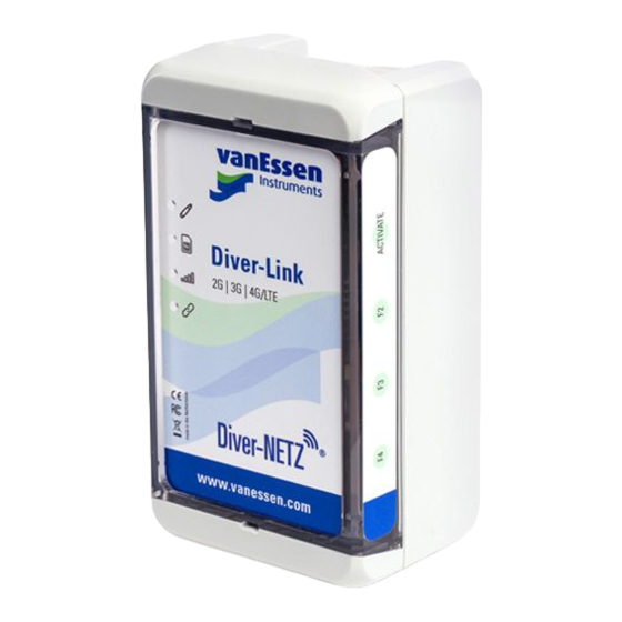
Page 6: Description
Diver interface and user interface. Views from the four main sides are shown in the figure below. Each side will be described below. © April 2023 Van Essen Instruments. All rights reserved. www.vanessen.com... - Page 7 Diver- Link connects with the cellular network. See Appendix I Technical Specifications section Integrated Barometric Datalogger for the specifications of the integrated barometric datalogger. © April 2023 Van Essen Instruments. All rights reserved. www.vanessen.com...
-
Page 8: Preparation And Deployment
The following sections describe how to configure and install the Diver-Link. The steps are: Prepare the Diver-Link Open the Diver-Link b. Insert the SIM card (if applicable) Insert the batteries with correct polarity d. Insert the desiccant Close the Diver-Link © April 2023 Van Essen Instruments. All rights reserved. www.vanessen.com... -
Page 9: Preparing The Diver-Link
Once a SIM card is obtained, install it in the Diver-Link as shown below. The SIM card slot is located near the hinge on the top side of the Diver-Link. © April 2023 Van Essen Instruments. All rights reserved. www.vanessen.com... -
Page 10: Configuring The Diver-Link
Before configuring the Diver-Link a project must be setup in Diver-HUB. The project structure, including monitoring point information, will be used to configure all Diver- project. For more details see the Diver-HUB Getting Started Guide. © April 2023 Van Essen Instruments. All rights reserved. www.vanessen.com... -
Page 11: Programming The Diver
(see Appendix 5.8) to adjust and secure the DXT Cable to the top of casing. The system is now ready to be installed in a well. The system can be tested prior to deployment by activating the Diver-Link as outlined in the next section. © April 2023 Van Essen Instruments. All rights reserved. www.vanessen.com... - Page 12 Diver connected to port 1. The Diver LED indicator turns red for approximately 2 seconds in case of a connection issue with the Diver, for example no Diver is connected. © April 2023 Van Essen Instruments. All rights reserved. www.vanessen.com...
-
Page 13: Signal Quality
Once the Diver-Link is positioned in its position in the well, start the activation to verify the system is working properly. 2.7 Signal Quality The cellular signal quality depends on several factors, including coverage area, antenna type, and objects in the area that may cause interference. © April 2023 Van Essen Instruments. All rights reserved. www.vanessen.com... - Page 14 Consider moving the Diver-Link to a different area to test reception. If the system cannot be moved, consider using a different type of antenna that can be mounted away from potential interference. © April 2023 Van Essen Instruments. All rights reserved. www.vanessen.com...
-
Page 15: Appendix I Technical Specifications
B9, B12, B13, B14, B18, DN431-3, B19, B20, B25, B26, B28 DN432-3 3.3 Power Consumption External supply voltage 3 to 16 V Standby current < 50 A Average transmission current 500 mA © April 2023 Van Essen Instruments. All rights reserved. www.vanessen.com... -
Page 16: Environmental
400 to 1150 cmH Accuracy (max) ± 2.0 cmH Accuracy (typical) ± 1.0 cmH Long-term stability ± 2 cmH Resolution 0.1 cmH Display resolution 0.03 cmH Overload pressure 1.5 mH © April 2023 Van Essen Instruments. All rights reserved. www.vanessen.com... - Page 17 If a sample of the Diver falls between two data points of the barometric data, then nearest barometric pressure value is used at the time of the Diver sample. The same principle applies for the temperature data. © April 2023 Van Essen Instruments. All rights reserved. www.vanessen.com...
- Page 18 400 cmH O and -20 °C in the barometric datalogger data. The barometric datalogger memory is cleared when the Diver-Link is moved to another monitoring point and/or project. © April 2023 Van Essen Instruments. All rights reserved. www.vanessen.com...
-
Page 19: Appendix Ii Led Indicators & Function Keys
Diver-Link or the last scheduled communication session with the server. The Diver-Link will not wake up or perform any action when the Status is activated. © April 2023 Van Essen Instruments. All rights reserved. www.vanessen.com... -
Page 20: Led Indicators
Diver connected to port 1. The Diver LED indicator turns red for approximately 2 seconds in case of a communication issue with the Diver, for example no Diver is connected. © April 2023 Van Essen Instruments. All rights reserved. www.vanessen.com... - Page 21 Check antenna position 2. Use other Diver-Link to check if providers are available. 3. Move Diver-Link to a location where you know connection is available to check if the hardware works properly. © April 2023 Van Essen Instruments. All rights reserved. www.vanessen.com...
- Page 22 No connection with Diver Check if the DXT Cable and Diver are connected properly. Check DXT Cable and Diver using alternative cables or USB Reading Unit. Replace DXT Cable or Diver. © April 2023 Van Essen Instruments. All rights reserved. www.vanessen.com...
- Page 23 2. When a local SIM card from a third party is used, please check APN settings with provider, contact VEI support. 3. Check antenna position when using a model with an external antenna. © April 2023 Van Essen Instruments. All rights reserved. www.vanessen.com...
-
Page 24: Appendix Iii Diver-Link Accessories
Office is easy-to-use and has an intuitive user interface. • Barometric compensation • Units: Metric and U.S. • 7 languages: Dutch, English, French, Free download from www.vanessen.com German, Polish, Portuguese and Spanish © April 2023 Van Essen Instruments. All rights reserved. www.vanessen.com... -
Page 25: Diver-Hub Software
USB port on the other, for connection to a laptop computer. The Smart Interface Cable allows for data download, programming settings, or starting/stopping the Diver while in Part no: AS346 the field. © April 2023 Van Essen Instruments. All rights reserved. www.vanessen.com... -
Page 26: Dxt Cable
The TD-Diver is available in the following pressure ranges: 10 m, 20 m, 50 m and 100 m. Part no: DI8xx © April 2023 Van Essen Instruments. All rights reserved. www.vanessen.com... -
Page 27: Baro-Diver
The Cera-Diver is available in the following Part no: DI7xx pressure ranges: 10 m, 20 m, 50 m and 100 m. © April 2023 Van Essen Instruments. All rights reserved. www.vanessen.com... -
Page 28: Micro-Diver
Part no: DI28x averaging and pumping test. The CTD-Diver is available in the following pressure ranges: 10 m, 50 m, 100 m and 200 m. © April 2023 Van Essen Instruments. All rights reserved. www.vanessen.com...
Need help?
Do you have a question about the Diver-Link DN4 Series and is the answer not in the manual?
Questions and answers