
Related Manuals for Baker Hughes Masoneilan 72000 Series


Summary of Contents for Baker Hughes Masoneilan 72000 Series
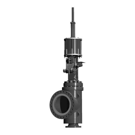
- Page 1 72000 Series Large Mass Flow Energy Management Control Valves Instruction Manual (Rev. A) Baker Hughes Data Classification : Public...
- Page 2 OPERATOR ARE STRICTLY LIMITED TO THOSE EXPRESSLY PROVIDED IN THE CONTRACT RELATING TO THE SUPPLY OF THE EQUIPMENT. NO ADDITIONAL REPRESENTATIONS OR WARRANTIES BY BAKER HUGHES REGARDING THE EQUIPMENT OR ITS USE ARE GIVEN OR IMPLIED BY THE ISSUE OF THESE INSTRUCTIONS.
- Page 3 Packing Box Assembly ......................................10 Bolt Torquing Sequence ......................................10 Parts Reference For 72000 Series Control Valve ..............................12 Actuation .............................................14 Parts Reference Table 51/52/53 Actuators ................................23 Masoneilan 72000 Series Control Valves Instruction Manual | c Copyright 2021 Baker Hughes Company. All rights reserved.
- Page 4 | Baker Hughes Copyright 2021 Baker Hughes Company. All rights reserved.
- Page 5 Indicates a potentially hazardous situation which, if not avoided, could result in serious injury. Items sold by Baker Hughes are warranted to be free from defects in materials and workmanship for a period of one year from the date of shipment provided said items are used according to Baker Hughes recommended usages.
-
Page 6: Numbering System
5 Metal Seal Ring and Metal Seat 53 Cylinder Spring Return 6 Polymeric Seal (Air to Open) Ring and Metal Seat 9 Graphite Seal Ring and Metal Seat 2 | Baker Hughes Copyright 2021 Baker Hughes Company. All rights reserved. -
Page 7: Installation
Care must be exercised when unpacking the valve to prevent damage to the accessories and component parts. Contact the local Baker Hughes Sales Office or Service Center with any issues or problems. Be sure to note the valve model number and serial number in all correspondence. - Page 8 Disconnect all mechanical connections between the positioner to welding any valves inline. Refer any additional and the other instruments. Disassemble the valve stem and questions to the local Baker Hughes Sales Office or actuator stem coupling as described in the following sections. Service Center.
-
Page 9: Valve Disassembly
(10), and (if applicable) the cage retainer (11) to remove from the valve body (1). Figure 3 - Straight Plug Design Masoneilan 72000 Series Control Valves Instruction Manual | 5 Copyright 2021 Baker Hughes Company. All rights reserved. -
Page 10: Maintenance And Repair
(16) on the packing flange compressing the packing rings. (17). Periodic re-tightening of the packing flange nuts may be required to maintain proper sealing. 6 | Baker Hughes Copyright 2021 Baker Hughes Company. All rights reserved. - Page 11 Note: For more details on the lapping procedure and seat- ing angles, please consult the factory and provide the valve serial number (found on the serial plate on the actuator). Masoneilan 72000 Series Control Valves Instruction Manual | 7 Copyright 2021 Baker Hughes Company. All rights reserved.
-
Page 12: Valve Reassembly
EDGE MUST BE FREE FROM NICKS 40°30' AND BURRS 39°30' Figure 7 - Bonnet Seating Angle Details (see page 12, detail B) Figure 8 - Installing Seal Ring 8 | Baker Hughes Copyright 2021 Baker Hughes Company. All rights reserved. -
Page 13: Bonnet Assembly
Dow III, into the gasket groove to retain the gasket during assembly. Masoneilan 72000 Series Control Valves Instruction Manual | 9 Copyright 2021 Baker Hughes Company. All rights reserved. - Page 14 Table 2) consult factory for other arrangements not shown on the table. Use the tightening sequence as indicated in Figure 9. Figure 9 - Bolt Torque Sequence 10 | Baker Hughes Copyright 2021 Baker Hughes Company. All rights reserved.
- Page 15 Parts may differ according to specific valve supplied. All parts may not be applicable. ● Recommended Spare Parts (some parts may not be applicable to all designs) Masoneilan 72000 Series Control Valves Instruction Manual | 11 Copyright 2021 Baker Hughes Company. All rights reserved.
- Page 16 DETAIL B DETAIL C SCALE 2 : 3 SCALE 2 : 3 Figure 10 - 72000 Series Cross Section 12 | Baker Hughes Copyright 2021 Baker Hughes Company. All rights reserved.
- Page 17 Note: For model 724XX valves, use N2 values in Table 4 to ensure seating tightness of the pilot plug. Table 4 - Type 88, Air to Retract - valve seating Masoneilan 72000 Series Control Valves Instruction Manual | 13 Copyright 2021 Baker Hughes Company. All rights reserved.
- Page 18 900 or 1500 0.08 3 and 4 0.12 150, 300 or 600 900 or 1500 0.24 10, 12 and 16 0.275 Table 6 - Auxiliary Pilot Plug Travel 14 | Baker Hughes Copyright 2021 Baker Hughes Company. All rights reserved.
- Page 19 Type 87 Air to Close No. 10-16-23 No. 10-16-23 Model 87 Actuator Model 88 Actuator Air to Retract (Open) Air to Extend (Close) Figure 11 Masoneilan 72000 Series Control Valves Instruction Manual | 15 Copyright 2021 Baker Hughes Company. All rights reserved.
- Page 20 7. Assemble and tighten Indicator Arm (23), Spring Lock Washers (25), and Hexagon Bolts (24). 8. Line up the indicator plate (26), with Indicator arm (23) and check actuator for proper operation. 16 | Baker Hughes Copyright 2021 Baker Hughes Company. All rights reserved.
- Page 21 51 Double Acting 51 Double Acting Model Model With handwheel without volume chamber With handwheel with volume chamber Figure 14 Masoneilan 72000 Series Control Valves Instruction Manual | 17 Copyright 2021 Baker Hughes Company. All rights reserved.
- Page 22 Model 51 Double Acting Without handwheel without volume chamber 51 Double Acting Model Without handwheel with volume chamber Figure 15 18 | Baker Hughes Copyright 2021 Baker Hughes Company. All rights reserved.
- Page 23 Model Model Air to extend with handwheel Air to retract without handwheel Figure 16 Masoneilan 72000 Series Control Valves Instruction Manual | 19 Copyright 2021 Baker Hughes Company. All rights reserved.
- Page 24 Model Model Air to extend with handwheel Air to retract without handwheel Figure 17 20 | Baker Hughes Copyright 2021 Baker Hughes Company. All rights reserved.
- Page 25 CM, DM handwheel Typical for Models 51/52/53 Figure 18 Masoneilan 72000 Series Control Valves Instruction Manual | 21 Copyright 2021 Baker Hughes Company. All rights reserved.
- Page 26 Piston rod engagement Operating information plate Split clamp ● 45 Bearing Drive screw Indicator arm Retaining pin Separator plate (Model 51) Volume chamber tube Table 8 ● Recommended Spare Parts 22 | Baker Hughes Copyright 2021 Baker Hughes Company. All rights reserved.
- Page 27 Notes Masoneilan 72000 Series Control Valves Instruction Manual | 23 Copyright 2021 Baker Hughes Company. All rights reserved.
- Page 28 Copyright 2021 Baker Hughes Company. All rights reserved. Baker Hughes provides this information on an “as is” basis for general information purposes. Baker Hughes does not make any representation as to the accuracy or completeness of the information and makes no warranties of any kind, specific, implied or oral, to the fullest extent permissible by law, including those of merchantability and fitness for a particular purpose or use.
Need help?
Do you have a question about the Masoneilan 72000 Series and is the answer not in the manual?
Questions and answers