
Related Manuals for Baker Hughes Masoneilan 77000 Series


Summary of Contents for Baker Hughes Masoneilan 77000 Series
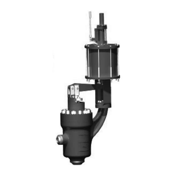
- Page 1 Masoneilan ™ 77000 & 77003 Series Axial Flow, Labyrinth Trim Control Valves Instruction Manual (Rev.D) Baker Hughes Data Classification: Public...
- Page 2 OPERATOR ARE STRICTLY LIMITED TO THOSE EXPRESSLY PROVIDED IN THE CONTRACT RELATING TO THE SUPPLY OF THE EQUIPMENT. NO ADDITIONAL REPRESENTATIONS OR WARRANTIES BY BAKER HUGHES REGARDING THE EQUIPMENT OR ITS USE ARE GIVEN OR IMPLIED BY THE ISSUE OF THESE INSTRUCTIONS.
- Page 3 Valve Disassembly 77001 and 77002 Series ............4 Maintenance & Repair ..................... 5 Packing Box ..........................5 Packing Replacement ......................... 5 Parts Repair ..........................5 Copyright 2021 Baker Hughes Company. All rights reserved. Masoneilan 77000 Series Control Valves Instruction Manual | c...
-
Page 4: Table Of Contents
Body / Bonnet / Body Gasket / Bolting Assembly ................ 14 Packing Box / Standard Packing Assembly ................. 16 Offset Actuator Mounting Linkage ....................17 Seat Lapping ..........................17 Linkage Assembly ....................18 d | Baker Hughes Copyright 2021 Baker Hughes Company. All rights reserved. - Page 5 DANGER CAUTION WARNING Items sold by Baker Hughes are warranted to be free from defects in materials and workmanship for a period of one year from the Indicates a potentially hazardous situation which, if not avoided, date of shipment provided said items are used according to could result in death or serious injury.
- Page 6 Only Masoneilan replacement parts should be used when The following instructions are designed to guide the user through carrying out maintenance operations. Obtain replacement parts the installation and maintenance of the Masoneilan 77000 Series through local Baker Hughes representatives or Masoneilan Parts control valves.
- Page 7 Contact the shutoff valve on each side of the control valve and a manually local Baker Hughes Sales Office or Service Center with any operated throttling valve in the bypass line. issues or problems. Be sure to note the valve model number and serial number in all correspondence.
- Page 8 For Top Entry 77002 Series Designs follow disassembly instructions 9-15: Remove the packing flange nuts (16), packing flange (14), and packing follower (13). 4 | Baker Hughes Copyright 2021 Baker Hughes Company. All rights reserved.
- Page 9 If so a maximum of .015” (0.4mm) The valve must be isolated and the process pressure vented prior to performing any packing box mainte- nance. Copyright 2021 Baker Hughes Company. All rights reserved. Masoneilan 77000 Series Control Valves Instruction Manual | 5...
-
Page 10: Valve Reassembly
For these designs there will not be a lower spider gasket as it is a one piece construction. 6 | Baker Hughes Copyright 2021 Baker Hughes Company. All rights reserved. -
Page 11: Body Bolting
1 stud thread or more that 2-1/2 stud threads are extended above the nut after final tightening, then double check the assembly for proper installation and alignment. Copyright 2021 Baker Hughes Company. All rights reserved. Masoneilan 77000 Series Control Valves Instruction Manual | 7... -
Page 12: Packing Box Assembly
Low-E Packing is only available with the spring loaded follower. Installation should be performed as detailed in the following paragraphs. Figure 6: Graphite Packing 8 | Baker Hughes Copyright 2021 Baker Hughes Company. All rights reserved. -
Page 13: Preparation
PTFE - female adapter PFE - V-Ring PTFE - V-Ring PFE - V-Ring PTFE - male adapter Figure 9 Copyright 2021 Baker Hughes Company. All rights reserved. Masoneilan 77000 Series Control Valves Instruction Manual | 9... -
Page 14: Valve Travel Requirements
Lower Guide Bushing (Top Entry Design Only) Spud Adapter (Bottom Entry Design Only) Actuator Link Clevis (Sizes 1” - 3”) Conical Spring (Top Entry Design Only) •Recommended spare parts for each maintenance interval 10 | Baker Hughes Copyright 2021 Baker Hughes Company. All rights reserved. - Page 15 Detail A Detail C Scale 2 : 5 Scale 2 : 5 Top Entry Figure 11: Parts Drawing for Bottom Entry 77001 Series Copyright 2021 Baker Hughes Company. All rights reserved. Masoneilan 77000 Series Control Valves Instruction Manual | 11...
- Page 16 Detail A Detail B Scale 1 : 2 Scale 1 : 2 Figure 12: Parts Drawing for Top Entry 77002 Series 12 | Baker Hughes Copyright 2021 Baker Hughes Company. All rights reserved.
-
Page 17: 77003 Series Disassembly
Make certain to remove both Trim Gaskets (B103) noting that one may be attached to the Liner Spider and one may remain inside the valve body. Copyright 2021 Baker Hughes Company. All rights reserved. Masoneilan 77000 Series Control Valves Instruction Manual | 13... -
Page 18: 77003 Series Reassembly
(B106) contacts the Trim Gasket (B103). Continue to lower Figure 13: Torque Sequence the assembly until seated. Remove hoist and lift eye. Note: Tighten bonnet nuts in five equal steps. 14 | Baker Hughes Copyright 2021 Baker Hughes Company. All rights reserved. - Page 19 PACKING FLANGE B212 PACKING FOLLOWER B207 PACKING SET B200 PACKING STUDS B201 PACKING NUTS B127 SPACER Figure 15: 77003 Series 3-Stage Unbalanced (Trim Y) Copyright 2021 Baker Hughes Company. All rights reserved. Masoneilan 77000 Series Control Valves Instruction Manual | 15...
-
Page 20: Packing Box / Standard Packing Assembly
PACKING FOLLOWER B213 PACKING FLANGE B212 PACKING FOLLOWER B207 PACKING SET B211 LANTERN RING B207 PACKING SET B200 PACKING STUDS B200 PACKING STUDS B201 PACKING NUTS B201 PACKING NUTS 16 | Baker Hughes Copyright 2021 Baker Hughes Company. All rights reserved. -
Page 21: Offset Actuator Mounting Linkage
17. Loosen the packing packing nuts (B106) to remove friction and allow the plug/stem (B122) to rest against the liner/seat (B106) by its own weight. Copyright 2021 Baker Hughes Company. All rights reserved. Masoneilan 77000 Series Control Valves Instruction Manual | 17... -
Page 22: Linkage Assembly
VALVE CLEVIS CLAMP SCREW A900 LINK PIN SNAP RINGS A044 ACTUATOR CONNECTOR A915b ACT. CONNECTOR BOLTING A915a BRACKET TO ACTUATOR BOLTS A060 ACTUATOR SPUD ADAPTER A815 GREASE FITTING 18 | Baker Hughes Copyright 2021 Baker Hughes Company. All rights reserved. - Page 23 Notes: Copyright 2021 Baker Hughes Company. All rights reserved. Masoneilan 77000 Series Control Valves Instruction Manual | 19...
- Page 24 Copyright 2021 Baker Hughes Company. All rights reserved. Baker Hughes provides this information on an “as is” basis for general information purposes. Baker Hughes does not make any representation as to the accuracy or completeness of the information and makes no warranties of any kind, specific, implied or oral, to the fullest extent permissible by law, including those of merchantability and fitness for a particular purpose or use.
Need help?
Do you have a question about the Masoneilan 77000 Series and is the answer not in the manual?
Questions and answers