BWT SWIMLINE RTEMP CFP-100 Instructions For Installation And Use Manual
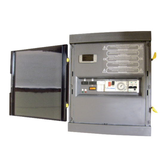
Filtration electrical panel with regulation
Hide thumbs
Also See for SWIMLINE RTEMP CFP-100:
Table of Contents
Advertisement
Available languages
Available languages
Quick Links
Advertisement
Chapters
Table of Contents

Related Manuals for BWT SWIMLINE RTEMP CFP-100


Summary of Contents for BWT SWIMLINE RTEMP CFP-100
- Page 1 SWIMLINE Coffret de commande de filtration avec régulation RTEMP CFP-100 NOTICE D’INSTALLATION ET CONSEILS D’UTILISATION (à lire attentivement et à conserver pour utilisation ultérieure) FR | PAGE 1 - GB | PAGE 13 1/24 CONSTRUCTION & RÉNOVATION 2021/01 - Indice de révision : E - Code : 32550...
-
Page 2: Table Of Contents
1. DESCRIPTION PRODUIT ................3 2. FONCTION DU PRODUIT ................3 3. NOMBRE DE PERSONNES, TEMPS DE POSE ET OUTILLAGE ....4 4. RESTRICTION D’USAGE ................4 5. PRÉCONISATION ET CONSIGNES DE SÉCURITÉ ........4 6. ENTRETIEN MAINTENANCE HIVERNAGE ..........4 7. -
Page 3: Description Produit
DESCRIPTION PRODUIT Coffret de filtration avec régulation automatique du temps de filtration en fonction de la température de l’eau. L’horloge est remplacée par un automate bénéficiant d’un algorithme optimisé. La régulation automatique comprend : • 1 automate. • 1 sonde de température de 6 m. •... -
Page 4: Nombre De Personnes, Temps De Pose Et Outillage
NOMBRE DE PERSONNES, TEMPS DE POSE ET OUTILLAGE • 1 personne • Pose coffret 10min • Pose doigt de gant 15min • Raccordement électrique 15min RESTRICTION D’USAGE • La pompe de filtration devra avoir une consommation inférieure à 10A. • Les coffrets équipés d’un transformateur 100VA devront alimenter 2 projecteurs halogènes ou led ne dépassant pas 50w (chacun) et fonctionnant en 12VAC. -
Page 5: Instructions De Montage ( Cfp - 100 )
INSTRUCTIONS DE MONTAGE ( CFP - 100 ) Débloquer les 6 vis plastique et retirer la face avant Retirer la vis de maintien de l’étrier Fixer l’étrier au mur à l’aide des chevilles et vis Utiliser l’étrier comme gabarit de perçage fournies Accrocher le coffret sur l’étrier et remettre la vis en Accrocher le disjoncteur-moteur sur le rail au dessus... -
Page 6: Réglage De L'horloge
RÉGLAGE DE L'HORLOGE MODE D’EMPLOI : Mettrez l’horloge à l’heure en synchronisant la roue sur l’heure réelle. Utilisez un tournevis que vous introduirez au centre de la roue pour positionner les aiguilles comme sur une montre : la grande aiguille représente les minutes, la petite aiguille représente les heures). -
Page 7: Instructions Pour Le Câblage
INSTRUCTIONS POUR LE CÂBLAGE Les instructions ci-après concernent uniquement les connexions qui doivent être effectuées par l’installateur. Le câblage du coffret est déjà réalisé lors de la fabrication et ne doit en aucun cas être modifié au risque de dégradations ou d’accidents. Il est primordial d’utiliser des câbles de section suffisante en fonction de l’intensité... -
Page 8: Montage Doigt De Gant
MONTAGE DOIGT DE GANT Couper le joint du doigt de gant avant de position- ner ce dernier dans l'embout fileté. Ne garder que la partie conique du joint. Embout fileté en 3/4" femelle à coller en 40 mm code : 1364034 Doigt de gant Non fournis Té... -
Page 9: Utilisation De L'afficheur
UTILISATION DE L’AFFICHEUR Mode manuel sélectionné par la touche Choix du mode manuel ou auto Forçage pompe en marche Marche / Arrêt Pompe en fonctionnement Mode manuel sélectionné Mode auto sélectionné par la touche Mode auto sélectionné La touche SET permet la visualisation de l’heure de démarrage quotidien de la filtration. Un appui maintenu sur la touche SET pendant 3 secondes permet le réglage de l’heure de démarrage. - Page 10 4.2 PROPOSITION DE FACE AVANT • • • • • • • • • • • 3.1 MODE MANUEL 3.2 MODE AUTOMATIQUE 0° C <=Temp<=2° C 24 h 2° C < Temp < = 6° C: 6 ° C < Temp < = 32° Cycle: (ALF*Temp –...
- Page 11 et . ÷ ≤ ± ± ÷ ÷ Précision du régulateur à 25 ° C : digit. ±0,1 ° C ±1 XR20CX version PROCOPI.doc 11/24 CONSTRUCTION & RÉNOVATION 2021/01 - Indice de révision : E - Code : 32550...
-
Page 12: Schéma Électrique Partie Filtration
SCHÉMA ÉLECTRIQUE PARTIE FILTRATION En monophasé, réalisez les ponts suivants : • la phase entre L2 et L3 • le neutre entre N et L1 12/24 2021/01 - Indice de révision : E - Code : 32550 CONSTRUCTION & RÉNOVATION... - Page 13 SWIMLINE Filtration electrical panel with regulation RTEMP CFP-100 INSTRUCTIONS FOR INSTALLATION AND USE (Please read these instructions carefully and keep them for future reference.) FR | PAGE 1 - GB | PAGE 13 13/24 CONSTRUCTION & RÉNOVATION 2021/01 - Indice de révision : E - Code : 32550...
- Page 14 1. PRODUCT DESCRIPTION ................15 2. PRODUCT FUNCTION ................15 3. NUMBER OF PEOPLE, TIME AND TOOLS REQUIRED FOR INSTALLATION ........................16 4. RESTRICTIONS ..................16 5. SAFETY ADVICE AND RECOMMENDATIONS ........... 16 6. MAINTENANCE UPKEEP WINTERIZING ..........16 7. MOUNTING INSTRUCTIONS ( CFP - 100 ) ............ 17 8.
-
Page 15: Product Description
PRODUCT DESCRIPTION Filtration control panel with automatic regulation of the length of the filtration cycle as a function of water temperature. The timer is replaced with a PLC that features an optimised algorithm. Automatic regulation comprises: • 1 PLC. • 1 temperature sensor 6m. -
Page 16: Number Of People, Time And Tools Required For Installation
NUMBER OF PEOPLE, TIME AND TOOLS REQUIRED FOR INSTALLATION • 1 person • Mounting the control panel = 10min • Mounting the thermowell = 15min • Wiring = 15min RESTRICTIONS • The filtration pump must have a power consumption of less than 10A. •... -
Page 17: Mounting Instructions ( Cfp - 100 )
MOUNTING INSTRUCTIONS ( CFP - 100 ) Undo the 6 plastic screws and remove the front Remove the screw fastening the mounting bracket plate. to the panel. Fasten the mounting bracket to the wall using the Use the mounting bracket as a template for drilling. bushings and screws provided. -
Page 18: Setting The Timer
SETTING THE TIMER INSTRUCTIONS FOR USE : Set the timer to the right time by synchronizing the wheel to the current time. Insert a screw driver into the centre of the wheel to position the needles similar to the hands on a watch: the big needle corresponds to the minutes, the small hand shows the hours). -
Page 19: Wiring Instructions
WIRING INSTRUCTIONS The following instructions concern only the wiring that needs to be carried out by the installer. The control panel itself is pre-wired in the factory. Control panel wiring should under no circumstances be modified, to do so could lead to damage or accidents. The cables' cross sections must be sized for the current that they carry (particularly the underwater light cables). -
Page 20: Thermowell Assembly
THERMOWELL ASSEMBLY Remove the straight part of the seal from the thermowell before fitting it into the threaded port. Only retain the conical section of the seal. Threaded 3/4" female solvent 40 mm code : 1364034 Thermowell Not supplied tee F/F solvent 50x40x50 mm code: 1352540 20/24 2021/01 - Indice de révision : E - Code : 32550... -
Page 21: Using The Display
USING THE DISPLAY Manual mode, touch to select Switch between manual and auto mode Pump override active On/Off Pump running Manual mode selected Auto mode, touch to select Auto mode selected Use the SET key to view the daily filtration start time. To change the start time, keep the SET key held down for 3 seconds. - Page 22 Digital regulator XR20CX 1. Warning 1.1 Please read this notice carefully before using the device • These instructions should be kept close to the device for fast and easy access. • The device should only be used under the conditions described below. •...
- Page 23 Operating instructions Resolution: 0.1°C: 19.9-99.9 or 1°C or 1°F 5.4 How to switch to manual mode Regulator precision at 25°C: +/- 0.1°C +/- 1 digit Press the MAN key to swtich from automatic mode to manual mode. 8.1 XR20XC - Pump relay 8A 5.5 How to lock the key pad Power supply 12VAC/DC: connect to terminals 7 and 8 1.
-
Page 24: Wiring - Filtration Section
WIRING - FILTRATION SECTION For monophse installations, create the following bridges : • phase between L2 and L3 • neutral between N and L1 24/24 2021/01 - Indice de révision : E - Code : 32550 CONSTRUCTION & RÉNOVATION...
Need help?
Do you have a question about the SWIMLINE RTEMP CFP-100 and is the answer not in the manual?
Questions and answers