Advertisement
Quick Links
Advertisement

Related Manuals for Michigan Scientigic MicroTC

Summary of Contents for Michigan Scientigic MicroTC
- Page 1 MicroTC User Manual Michigan Scientific Corporation...
- Page 2 Copyright © 2023 Michigan Scientific Corporation Details and specifications provided in this document are purely for informational purposes and are subject to alterations. No liability is accepted for errors or omissions. Michigan Scientific Corporation 8500 Ance Road Charlevoix, MI 49720 Revision Date: 2/23/2023 8:47 a.m.
- Page 3 Contents Introduction Installation Operations Troubleshooting Guide...
- Page 4 The MicroTC Linear Thermocouple Amplifier... • Provides cold junction compensation, amplification and linearization of K-type thermocouple signals • Input signal is amplified to 5 mV per degree Celsius over a wide input range • Signal bandwidth, 2.35 kHz (other bandwidths available) •...
- Page 5 Specifications Input Range (5 mV/C Linear Output) -25 °C to 400 °C Range (with polynomial equation) -200 °C to 970 °C Output Range Min = -0.77 V; Max = 4.92 V ±2 °C Typical; ±3 °C Max Measurement Error Noise 0.01 Hz - 10 Hz 0.8 μV p-p Higher Bandwidths Available...
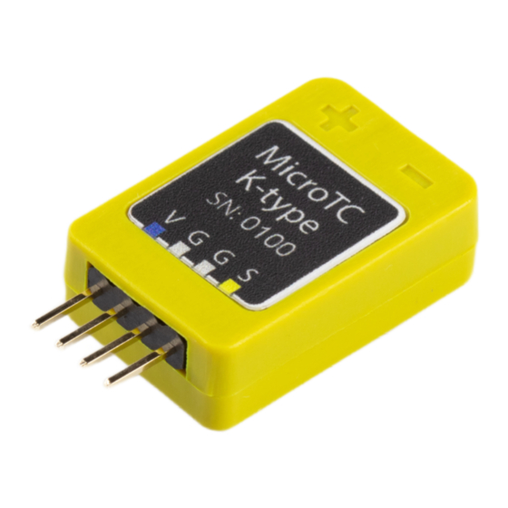
- Page 6 This will both protect the terminals from electrical shorting as well as provide strain relief for the wires. The signal terminals on the MicroTC are color coded and labeled to help determine which supply or output signal corresponds to which terminal. The...
- Page 7 Linearization Formulas The output of the MicroTC is a linear 5 mV/°C over an input range of -25 °C to 400 °C. Outside of this range, linearizing formulas can be used to determine temperature within the specified error. The following formulas use the voltage from the amplifier as the independent variable and generate temperature in °C.
- Page 8 Operations The MicroTC must be powered with +7 to +16 V and a common. See Electrical Installation section of this manual for instructions on how to connect these supplies to the proper terminals. The MicroTC signals should be measured with respect to the common terminal.
- Page 9 When using the MicroTC with a slip ring assembly, a separate signal common can be added to the stator of a slip ring to decrease the amount of rings needed, but it is important to place the amplifier as close as possible to the slip ring.
- Page 10 Bridge Excitation switch should be turned on, and the Shunt Calibration switch is unused. The Remote Amplifier Control Units reverse the polarity of the ±15 V terminals when the bridge excitation switch is off. The MicroTC-S will power off in this condition.
- Page 11 Troubleshooting Guide Problem Potential Cause Test to Verify Problem Solution Thermocouple could be Repair opening momentarily; thermocouple Output noisy with frequency response of data Look at dynamic signal junction thermocouple spinning acquisition system may be too with an oscilloscope Restrain slow to show complete drop thermocouple out of signal...
Need help?
Do you have a question about the MicroTC and is the answer not in the manual?
Questions and answers