Kostal Smart Energy Meter Operating Manual
Hide thumbs
Also See for Smart Energy Meter:
- Installation instructions manual (348 pages) ,
- Operating manual (112 pages)
Table of Contents
Advertisement
Quick Links
Advertisement
Table of Contents

Related Manuals for Kostal Smart Energy Meter


Summary of Contents for Kostal Smart Energy Meter
- Page 1 KOSTAL Smart Energy Meter Power measuring device Operating manual...
- Page 2 All names, trademarks, product names and other designations used in this manual may be legally pro- tected even if not indicated as such (e.g. as a trademark). KOSTAL Solar Electric GmbH assumes no li- ability for their free usage. The illustrations and texts have been compiled with great care. However, the possibility of errors cannot be ruled out.
-
Page 3: Table Of Contents
Notes in this manual ......................Navigation in the document ....................1.10 Labels on the energy meter ....................Device and system description ..................Using the KOSTAL Smart Energy Meter ................The KOSTAL Smart Energy Meter ..................LED statuses ........................Functions ..........................Connection variants ...................... - Page 4 Faults / maintenance......................113 Functions of the reset button ....................114 Error messages / displays ....................115 Exporting log data ....................... 116 Updating device firmware ....................117 Change password ....................... 118 Access tokens........................119 © 2022 KOSTAL Solar Electric GmbH...
-
Page 5: General Information
1.5 Proper use ........................10 1.6 Open Source licence....................... 11 1.7 EU declarations of conformity ..................12 1.8 Notes in this manual......................13 1.9 Navigation in the document..................... 15 1.10 Labels on the energy meter..................... 16 © 2022 KOSTAL Solar Electric GmbH... -
Page 6: Contact
General information 1.1 Contact Thank you for choosing a device from KOSTAL Solar Electric GmbH. If you have any technical questions, please call our service hotline: ■ Germany and other countries (language: German, English): +49 (0)761 477 44-222 ■ Switzerland: +41 32 5800 225 ■... -
Page 7: About This Manual
This manual is an integral part of the product. It applies exclusively to the device from KOSTAL Solar Electric GmbH. Keep this manual and give it to the new owner should you pass it onto a new operator. -
Page 8: Exclusion Of Liability
Factory settings may only be changed by qualified electrical installers or persons with at least comparable or higher technical qualifications, e.g. foremen, technicians or engineers. When doing so, all requirements are to be observed. © 2022 KOSTAL Solar Electric GmbH... -
Page 9: Target Group
■ Only carry out activities for which you have been qualified and instructed. ■ Observe the references to electricians in this manual. © 2022 KOSTAL Solar Electric GmbH... -
Page 10: Proper Use
The KOSTAL Smart Energy Meter is approved for use in EU member states. Only use the KOSTAL Smart Energy Meter in accordance with the details provided in the enclosed docu- mentation. -
Page 11: Open Source Licence
This product contains Open Source software, developed by third parties and licensed using vehicles including GPL and/or LGPL. For more details on this, a list of the Open Source software used and the related licence texts, go to the Licences section on the device’s website (Webserver). © 2022 KOSTAL Solar Electric GmbH... -
Page 12: Eu Declarations Of Conformity
General information 1.7 EU declarations of conformity KOSTAL Solar Electric GmbH hereby declares that the devices described in this document complies with the basic requirements and other relevant conditions of the directives listed below. ■ Directive 2014/30/EU (on the harmonisation of the laws of the Member States relating to electromagnetic compatibility (EMC)) ■... -
Page 13: Notes In This Manual
These must be followed at all times. The information notes also point out that failure to observe instructions may result in damage to property or financial damages. Warning symbols Danger © 2022 KOSTAL Solar Electric GmbH... - Page 14 Danger due to electrical shock and discharge Danger due to burns Symbols within the information notes The symbol indicates activities that may only be carried out by an electrician. Information or tip Important information Damage to property possible © 2022 KOSTAL Solar Electric GmbH...
-
Page 15: Navigation In The Document
In order to enable navigation through this document, it contains clickable areas. The table of contents takes you to the specified chapter in one click. You can navigate to the referenced points in the document within the instruction text using the cross-references. © 2022 KOSTAL Solar Electric GmbH... -
Page 16: Labels On The Energy Meter
Electrical installations require specialist skills Housing with protective insulation (protective class II). Device may not be disposed of with household waste. Observe the local application of disposal requirements CE marking The product satisfies the applicable EU requirements © 2022 KOSTAL Solar Electric GmbH... -
Page 17: Device And System Description
Device and system description 2. Device and system description 2.1 Using the KOSTAL Smart Energy Meter ..............18 2.2 The KOSTAL Smart Energy Meter................... 20 2.3 LED statuses ........................21 2.4 Functions ........................22 © 2022 KOSTAL Solar Electric GmbH... -
Page 18: Using The Kostal Smart Energy Meter
PIKO 4.2-20 ■ PIKO CI ■ PIKO EPC The inverters can be used in combination with the KOSTAL Smart Energy Meter for the fol- lowing applications: ■ Reading the current home consumption and output power ■ Power curtailment of inverters down to 0 W... - Page 19 ■ ENECTOR with convenience function These include advanced ENECTOR charging modes (e.g. Lock Mode, Power Mode, Solar Pure Mode, Solar Plus Mode). Some modes only work in combination with a KOSTAL inverter. © 2022 KOSTAL Solar Electric GmbH...
-
Page 20: The Kostal Smart Energy Meter
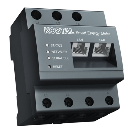
Device and system description 2.2 The KOSTAL Smart Energy Meter Inputs for external wires L1, L2, L3 Neutral wire N 2 x LAN connection RS485 connection (A) Pre-configured for PIKO IQ/PLENTICORE RS485 connection (B) Pre-configured for PIKO MP plus Outputs for external wires L1, L2, L3... -
Page 21: Led Statuses
Device and system description 2.3 LED statuses The LEDs inform the user of the status of the KOSTAL Smart Energy Meter. The following statuses are indicated: Status LED Colour State Description Orange On (<10 s) Device starting Green Flashes slowly... -
Page 22: Functions
2.4 Functions Recording home consumption Using the KOSTAL Smart Energy Meter enables the inverter to monitor the flow of energy in the home 24 hours a day and to control it in an optimum manner. The inverter primarily handles control. The PV energy generated is used firstly for self-con- sumption (such as lighting, the washing machine or TV). - Page 23 Operation, Page 67. The data logger A data logger is integrated in the KOSTAL Smart Energy Meter. The data logger is a data storage system, which collects and stores the error information. Such information is re- quired by the service team in the event of an error.
- Page 24 Device and system description KOSTAL Solar Portal The KOSTAL Solar Portal protects your investment in a PV system against yield losses, e.g. through active e-mail alerts of events. You can log in to the KOSTAL Solar Portal for free at www.kostal-solar-portal.com.
-
Page 25: Connection Variants
3.8 KSEM with PLENTICORE plus and ENECTOR AC 3.7/11 wallbox ........55 3.9 KSEM with PIKO MP plus and ENECTOR AC 3.7/11 wallbox ......... 56 3.10 Multiple-inverter connection of KOSTAL inverters............58 3.11 Configuring settings in the Webserver ................66... -
Page 26: Ksem With Plenticore Plus
Connection variants 3.1 KSEM with PLENTICORE plus The KOSTAL Smart Energy Meter (KSEM) can be used in conjunction with the PLENTICORE plus in the following variants. ■ 24-hour load/generation measurement ■ (measure the current home consumption and output power) ■... - Page 27 In this variant, the KOSTAL Smart Energy Meter runs as a slave and transmits data to the inverter. The inverter does not have to be set up in the KOSTAL Smart Energy Meter because it is pre-configured to the Modbus RTU RS485 interface (A) as standard.
- Page 28 When an inverter is selected, the predefined default values are adopted. These can be adapted if necessary. Parameter Value Interface RS485 A Mode Slave Presetting PIKO IQ/PLENTICORE Slave address Baud rate 38400 Data bits Parity None Stop bit © 2022 KOSTAL Solar Electric GmbH...
- Page 29 In this variant, the KOSTAL Smart Energy Meter runs as a slave and transmits data to the inverter. The inverter does not have to be set up in the KOSTAL Smart Energy Meter because it is pre-configured to the Modbus RTU RS485 interface (A) as standard.
- Page 30 For details, refer to the inverter’s operating manual. Setting on inverter only possible after logging in as an installer. If changes are to be made to the settings, perform the following steps: Call up online interface of KOSTAL Smart Energy Meter Calling up user inter- face, Page 70 Call up Modbus configuration under Modbus settings.
-
Page 31: Ksem With Plenticore Bi
NOTE For details, see the inverter's operating manual and the KOSTAL Smart Energy Meter's installation instructions. In this variant, the KOSTAL Smart Energy Meter runs as a slave and transmits data to the inverter. © 2022 KOSTAL Solar Electric GmbH... - Page 32 Connection variants The inverter does not have to be set up in the KOSTAL Smart Energy Meter because it is pre-configured to the Modbus RTU RS485 interface (A) as standard. If changes are to be made to the settings, perform the following steps:...
-
Page 33: Ksem With Piko Iq
Connection variants 3.3 KSEM with PIKO IQ The KOSTAL Smart Energy Meter (KSEM) can be used in conjunction with the PIKO IQ in the following variants. ■ 24-hour load/generation measurement (measuring the current home consumption and output power) ■ Multiple-inverter connection (several KOSTAL solar inverters in the same house grid,... - Page 34 In this variant, the KOSTAL Smart Energy Meter runs as a slave and transmits data to the inverter. The inverter does not have to be set up in the KOSTAL Smart Energy Meter because it is pre-configured to the Modbus RTU RS485 interface (A) as standard.
- Page 35 When an inverter is selected, the predefined default values are adopted. These can be adapted if necessary. Parameter Value Interface RS485 A Mode Slave Presetting PIKO IQ/PLENTICORE Slave address Baud rate 38400 Data bits Parity None Stop bit © 2022 KOSTAL Solar Electric GmbH...
-
Page 36: Ksem With Piko Mp Plus
Connection variants 3.4 KSEM with PIKO MP plus The KOSTAL Smart Energy Meter (KSEM) can be used in conjunction with the PIKO MP plus in the following variants. ■ 24-hour load/generation measurement (measuring the current home consumption and output power) ■... - Page 37 Install the KOSTAL Smart Energy Meter in the house grid as shown. NOTE The installation position of the KOSTAL Smart Energy Meter is set in the inverter. Set up RS485 communication cable between inverter and KOSTAL Smart Energy Meter and connect.
- Page 38 In this variant, the KOSTAL Smart Energy Meter runs as a slave and transmits data to the inverter. The inverter does not have to be set up in the KOSTAL Smart Energy Meter because it is pre-configured to the Modbus RTU RS485 interface (B) as standard.
- Page 39 Connection variants Parameter Value Stop bit © 2022 KOSTAL Solar Electric GmbH...
- Page 40 NOTE For details, see the inverter's operating manual and the KOSTAL Smart Energy Meter's installation instructions. In this variant, the KOSTAL Smart Energy Meter runs as a master and transmits data to the inverter and battery. ■ When setting up, note the following installation order:...
- Page 41 Switch on battery ■ Switch on inverter The PIKO MP plus and battery must be set up in the KOSTAL Smart Energy Meter. Do this by performing the following steps: Call up online interface of KOSTAL Smart Energy Meter Calling up user inter- face, Page 70...
- Page 42 This automatically sets the in- verter's maximum AC output power. Serial interface Select the RS485 interface at which the PIKO MP plus is connected to the KOSTAL NOTE! The preassigned interfaces have Smart Energy Meter. to be switched off beforehand. To do this, click on the corresponding interface in the note that appears.
- Page 43 Press the Save button to adopt the settings. ✔ The PIKO MP plus and battery have been set up in the KOSTAL Smart Energy Meter. © 2022 KOSTAL Solar Electric GmbH...
- Page 44 Press the OK button to adopt the settings. ✔ The battery has been set up in the KOSTAL Smart Energy Meter and linked to a PIKO MP plus. Finally, the battery still needs to be assigned to the correct DC input in the PIKO MP plus.
-
Page 45: Ksem With Piko 4.2-20 / Piko Epc
The KOSTAL Smart Energy Meter (KSEM) can be used in conjunction with the PIKO 4.2-20 or PIKO EPC in the following variants. NOTE It is possible to use the KOSTAL Smart Energy Meter in conjunction with the PIKO 4.2-20 or PIKO EPC as of inverter FW5.0. ■... - Page 46 Connection variants In this variant, the KOSTAL Smart Energy Meter runs as a master and controls the inverter (e.g. power limitation). NOTE For details, see the inverter's operating manual and the KOSTAL Smart Energy Meter's installation instructions. Set up inverter in KOSTAL Smart Energy Meter. Do this by performing the following steps:...
-
Page 47: Ksem With Piko Ci
Connection variants 3.6 KSEM with PIKO CI The KOSTAL Smart Energy Meter (KSEM) can be used in conjunction with the PIKO CI in the following variants. ■ 24-hour load/generation measurement (measuring the current home consumption and output power) ■ Multiple-inverter connection (several KOSTAL solar inverters in the same house grid,... - Page 48 NOTE In the KOSTAL CI app for the PIKO CI inverter, the installation position and the use of the KOSTAL Smart Energy Meter in the inverter must be set. For more information about settings in the inverter, refer to the inverter's operating manual.
- Page 49 NOTE In the KOSTAL CI app for the PIKO CI inverter, which you will find in your app store, the terminating resistor for the last inverter must be activated via the software. The installation position and use of the KOSTAL Smart Energy Meter must also be set in the inverter.
- Page 50 In this variant, the KOSTAL Smart Energy Meter runs as a slave and transmits data to the inverter. In the KOSTAL Smart Energy Meter, the PIKO CI still has to be selected for the RS485 in- terface (A). Do this by performing the following steps:...
-
Page 51: Ksem With Enector Ac 3.7/11 Wallbox
ENECTOR with KOSTAL Smart Energy Meter for blackout protection (house connection monitoring) If the ENECTOR is connected to a KOSTAL Smart Energy Meter and this is only to be used for blackout protection (house connection monitoring), the RS485 interface used must be configured in the KOSTAL Smart Energy Meter. - Page 52 KOSTAL Solar App. An activation code is required to set up the wallbox in the KSEM. NOTE In order for the wallbox to be set up in the KOSTAL Smart Energy Meter (KSEM), this function must first be activated via an activation code in the KSEM.
- Page 53 Connection variants Entering activation code in KOSTAL Smart Energy Meter The activation code is entered via the KSEM user interface. Log in to the KSEM on the user interface. Go to Activation code. Enter and confirm the 10-digit activation code for the wallbox.
- Page 54 All KOSTAL inverters and the KOSTAL Smart Energy Meter must be assigned to a PV sys- tem in the KOSTAL Solar Portal. If this was not been done when setting up your PV sys- tem, you must do it now.
-
Page 55: Ksem With Plenticore Plus And Enector Ac 3.7/11 Wallbox
If you have more than one inverter in the system (e.g. a PLENTICORE plus with battery and a PLENTICORE plus as PV inverter), set up power curtailment in the KSEM ( mul- tiple-inverter connection, Page 58) and observe the changes to the settling time. © 2022 KOSTAL Solar Electric GmbH... -
Page 56: Ksem With Piko Mp Plus And Enector Ac 3.7/11 Wallbox
NETWORK SERIAL BUS REST Only one KOSTAL Smart Energy Meter is required to monitor power and limit feed-in at the grid connection point. This is installed at the grid connection point in the house grid as shown in the illustrations. - Page 57 ■ Activate Modbus protocol in PLENTICORE plus ■ Set up PIKO MP plus in the KOSTAL Smart Energy Meter. It is important that the Mod- bus RS485 (slave) connection used has previously been enabled in the Modbus set- tings. ■...
-
Page 58: Multiple-Inverter Connection Of Kostal Inverters
In a multiple-inverter connection, up to 10 KOSTAL inverters can be used in the same house grid. Only one KOSTAL Smart Energy Meter is required to monitor power and limit feed-in at the grid connection point. This is installed at the grid connection point in the house grid as shown in the illustrations. - Page 59 KOSTAL Solar App and not in the individual inverter. To visualize the overall data, the KOSTAL Smart Energy Meter and all KOSTAL inverters must be added in the KOSTAL Solar Portal as devices of a PV system.
- Page 60 Set power limitation/feed-in limitation for the grid connection point in the KOSTAL Smart Energy Meter ■ Assign all KOSTAL inverters and the KOSTAL Smart Energy Meter to a PV system in the KOSTAL Solar Portal Communication connection The following devices must be connected to the KOSTAL Smart Energy Meter and the In- ternet via a LAN connection.
- Page 61 No further settings are required for the inverters. Configuring settling time For the KOSTAL Smart Energy Meter to achieve a rapid type of control with a set feed-in limitation (power limitation) or zero feed-in, the settling time must be configured in the KOSTAL inverters.
- Page 62 ■ RS485 (B): PIKO MP plus If changes are to be made to the settings, perform the following steps: Call up online interface of KOSTAL Smart Energy Meter Calling up user inter- face, Page 70 Call up Modbus configuration under Modbus settings.
- Page 63 Adding KOSTAL inverters in the KOSTAL Smart Energy Meter All KOSTAL inverters in a multiple-inverter connection that are to be measured and con- trolled using the KOSTAL Smart Energy Meter must be set up in the KOSTAL Smart Energy Meter.
- Page 64 Incorrect time information during data transfer to the KOSTAL Solar Portal Check the time and time zone set in the KOSTAL Smart Energy Meter and correct them if necessary. If the time is set incorrectly, the data will be transferred from KSEM with in- correct time information and will not be displayed correctly in the KOSTAL Solar Portal.
- Page 65 NOTE In conjunction with a battery storage system and additional inverters, power curtailment is activated in the KOSTAL Smart Energy Meter. If there is only one PLENTICORE plus in the system, power curtailment is configured in the inverter. © 2022 KOSTAL Solar Electric GmbH...
-
Page 66: Configuring Settings In The Webserver
After commissioning, further settings can be configured using the KOSTAL Smart Energy Meter’s online interface. To do this, use your PC or tablet to log in to the KOSTAL Smart Energy Meter. You will find a detailed description in Operation, Page 67. -
Page 67: Operation
Operation 4. Operation 4.1 The Webserver........................ 68 4.2 Preparing KOSTAL Smart Energy Meter................69 4.3 Calling up user interface....................70 4.4 Configuring settings ......................72 4.5 The dashboard ....................... 73 4.6 Menu - smart meter ......................74 4.7 Menu - wallbox ....................... 75 4.8 Menu –... -
Page 68: The Webserver
Operation 4.1 The Webserver The Webserver forms the graphic interface between the KOSTAL Smart Energy Meter and user. Go to Login to log in to the KOSTAL Smart Energy Meter. NOTE To log in, you will need the password from the energy meter’s type plate, which can be found on a separate instruction leaflet in the packaging. -
Page 69: Preparing Kostal Smart Energy Meter
Operation 4.2 Preparing KOSTAL Smart Energy Meter The KOSTAL Smart Energy Meter has to be connected to an existing local network in order for you to access it. This requires the following steps: Install the KOSTAL Smart Energy Meter in a distributor box on the top-hat rail accord- ing to the installation instructions provided and connect by cable. -
Page 70: Calling Up User Interface
The user interface is called up using a standard browser on a PC, tablet or mobile phone. To do this, enter host name or IP address of the KOSTAL Smart Energy Meter in your browser’s address line. The factory host name is made up of the product name and serial number. - Page 71 To log in, you will need the password from the energy meter’s type plate, which can be found on a separate instruction leaflet in the packaging. ✔ The KOSTAL Smart Energy Meter’s user interface opens. © 2022 KOSTAL Solar Electric GmbH...
-
Page 72: Configuring Settings
If you want to make changes to the settings on the KOSTAL Smart Energy Meter interfaces, you can do this by selecting an inverter for the interface in the Modbus settings. If you are using an ENECTOR AC 3.7/11 wallbox, alternatively you can deactivate the slave interface... -
Page 73: The Dashboard
The dashboard provides the user with an overview of the current most important KOSTAL Smart Energy Meter data. NOTE For the energy values to be displayed accurately, the KOSTAL Smart Energy Meter has to be installed at the grid connection point because otherwise not all consumers in the house grid can be recorded. -
Page 74: Menu - Smart Meter
The active energy is the power generated over a certain period. It is stated in watt-hours. Measuring values per phase The table shows all measuring values recorded by the system per phase. In advanced mode, apparent and reactive power/energy are also displayed. © 2022 KOSTAL Solar Electric GmbH... -
Page 75: Menu - Wallbox
KOSTAL Smart Energy Meter) The Wallbox menu only appears if the function has been activated on the KOSTAL Smart Energy Meter using an activation code Menu - activation code, Page 93... - Page 76 KOSTAL Smart Energy Meter via Add. Click on the Addbutton. Give the charging device a name. Select the RS485 interface on the KOSTAL Smart Energy Meter where the wallbox is connected to the KSEM (RS485 B is the default here). NOTE Note that the RS485 interface must be enabled in the Modbus settings beforehand.
- Page 77 The maximum charging power that the wallbox is to provide is set via DIP switches in the wallbox. For vehicles that can only be charged 1-phase, the maximum charging power is 3.7 kW. For vehicles that can be charged 3-phase, the maximum charging power is 11 kW. © 2022 KOSTAL Solar Electric GmbH...
- Page 78 Operation Solar Pure Mode (solar charging) Solar charging is only possible in combination with a PV system and the KOSTAL Smart Energy Meter. The PV system supplies the power needed to charge the electric vehicle. With this function, the electric vehicle is only charged using the PV surplus.
- Page 79 If the necessary excess power is not available, charging is maintained for approx. 5 minutes at the minimum charging power to avoid unnecessary switching on and off. After the hysteresis time has elapsed, charging is interrupted and only resumed after a wait time of approx. 8 minutes. © 2022 KOSTAL Solar Electric GmbH...
- Page 80 Solar Plus Mode (solar-optimised charging) Solar-optimised charging is only possible in combination with a PV system and the KOSTAL Smart Energy Meter. The PV system supplies the energy needed to charge the electric vehicle. If there is a PV surplus at the grid interconnection point, the amount drawn from the grid is replaced by the PV power or, if possible, increased to the PV surplus.
- Page 81 If the necessary excess power is not available, charging is maintained for approx. 5 minutes at the minimum charging power to avoid unnecessary switching on and off. After the hysteresis time has elapsed, charging is interrupted and only resumed after a wait time of approx. 8 minutes. © 2022 KOSTAL Solar Electric GmbH...
- Page 82 PLENTICORE BI) If a KOSTAL battery system with the PLENTICORE plus or PLENTICORE BI components is installed in the system, this inverter must be set up via the IP address in the KOSTAL Smart Energy Meter (via Inverter > Devices).
- Page 83 If the value exceeds the limit range of the rated current shown (shaded area), the charging current is reduced in order to not overload the grid connection point and thus the house fuse (blackout protection). © 2022 KOSTAL Solar Electric GmbH...
- Page 84 Advanced settings Some electric vehicles may experience problems with low charging currents. The 2011 CP EV out of signaled duty range ID is output as an event in the KOSTAL Smart Energy Meter. If this happens, a higher minimum charging current can be selected to remedy the problem.
- Page 85 Operation Updating wallbox firmware This menu item can be used to manually update the wallbox firmware via KOSTAL Smart Energy Meter G2 . The following requirements must be met: ■ The wallbox is connected to the KOSTAL Smart Energy Meter via an RS485 connec- tion.
-
Page 86: Menu - Tariff
Consumption and tariff information for the feed-in and consumption. The tariffs for feed-in and consumption (purchase) are stated under the tariff setting. NOTE The diagram also shows the energy in kWh and the costs in the configured currency. © 2022 KOSTAL Solar Electric GmbH... - Page 87 Here you select the currency and set the monthly basic charge for the tariff. The working price for the tariff for feed-in or consumption (purchase) can be set using the pen symbol next to the tariff view © 2022 KOSTAL Solar Electric GmbH...
- Page 88 Then select the days and hours for which the working price is to apply and assign these us- ing the Assign button. The colours indicate which working price/tariff applies to which time period. NOTE If a created working price is not assigned a time window, it is automatically deleted after saving. © 2022 KOSTAL Solar Electric GmbH...
-
Page 89: Menu - Plant Overview/Settings
Settings: More setting options for power limitation and diagnosis Using the various statistics, the user can display the current values for home consumption, KOSTAL Smart Energy Meter, inverter, amount drawn from the grid and wallbox. Detailed information can be displayed by expanding the statistics. - Page 90 KOSTAL Smart Energy Meter (KSEM) Parameter Explanation Curtailment at the grid In the KOSTAL Smart Energy Meter, an optional power limita- feed-in point tion for the entire system can be activated and configured in the settings. The set value is displayed here.
- Page 91 Current charging duration. Settings for plant overview This item can be used as an option to define a feed-in limit for the entire system metered by the KOSTAL Smart Energy Meter when using a multiple-inverter connection. Parameter Explanation Activate power limitation Here, a set power limitation for an entire sys- tem can be activated or deactivated.
- Page 92 NOTE! For power limitation with several inverters, each connected KOSTAL in- verter must be added in the KOSTAL Smart Energy Meter. Third-party inverters or non-selectable devices cannot be con- trolled via the KOSTAL Smart Energy Meter.
-
Page 93: Menu - Activation Code
4.10 Menu - activation code Activation code entry Released extra options Additional options (e.g. wallbox) can be activated in the KOSTAL Smart Energy Meter (KSEM) via an activation code. An activation code can be purchased from the KOSTAL Solar Webshop. -
Page 94: Menu - Inverter
Overview of the connected devices Connected devices Option for configuring connected devices The KOSTAL Smart Energy Meter is linked to the KOSTAL solar inverters to reduce the feed-in capacity of inverters, if required, or to control the battery when using the PIKO MP plus. - Page 95 Different parameters have to be configured depending on the device type. If all relevant set- tings have been configured, detection of the inverter can be started by pressing the OK button. NOTE Only then is a device added to the KOSTAL Smart Energy Meter if the inverter was de- tected successfully. Parameter Explanation PIKO MP plus A PIKO MP plus inverter is to be set up.
- Page 96 A battery is to be set up for a set-up PIKO MP plus. Linking with inverter Select the inverter to which the battery is connected. This must be set up beforehand so that it is displayed here. Serial interface © 2022 KOSTAL Solar Electric GmbH...
- Page 97 Explanation The battery communicates using the RS485 interface. To con- nect the battery, you will need to specify which RS485 interface of the KOSTAL Smart Energy Meter the battery’s communica- tion cable was connected to. Battery type Select the battery type, e.g. BYD HVM or BYD HVS.
- Page 98 Operation Parameter Explanation Name Shows the name which the user has given to the KOSTAL solar inverter. The name is assigned via the inverter menu interface. Type Shows the type designation of the inverter/battery. Address Either the IP address or RS485 address of the inverter is shown.
-
Page 99: Menu - Solar Portal
In order for the data in the solar portal to display the correct time values, it is important that the correct time zone and time are selected in the KOSTAL Smart Energy Meter un- der Device settings > Device > Date and time. -
Page 100: Menu - Modbus Settings
In this case, Modbus TCP communication must also be activated in the inverter. The TCP functionality must only be activated if the KOSTAL Smart Energy Meter is to be quer- ied by an external device via Modbus TCP (Modbus TCP slave). - Page 101 Operation Modbus RTU KOSTAL solar inverters, but also other devices, can be connected to the Modbus RTU RS485 interface. In Modbus RTU Slave mode, the KOSTAL Smart Energy Meter provides the measurement data via the RS485 interface. However, in Modbus RTU Master mode, measurement data is sent and written to other slave devices in order to control them.
- Page 102 Defines the parity of the connection Stop bits Defines the number of stop bits Modbus TCP Other devices that evaluate the data of the KOSTAL Smart Energy Meter can be connected to the Modbus TCP (LAN) interface. © 2022 KOSTAL Solar Electric GmbH...
- Page 103 Operation “Master” mode In “Master” mode, the KOSTAL Smart Energy Meter sends and writes information to the re- gisters of the configured slaves. These are added by entering the slave IP address. NOTE The internal present value registers and the internal energy value registers can be trans- mitted and written.
- Page 104 Clicking on Accept adds the certificate to the trusted certificates and it is then con- sidered to be accepted. A secure TLS connection can now be established from receiv- ers that use this certificate. © 2022 KOSTAL Solar Electric GmbH...
- Page 105 Groups of registers can be selected here, which are to be written in master mode. The sys- tem load of the KOSTAL Smart Energy Meter can therefore be reduced if all of the registers are not required. This may be necessary if lots of devices are connected to the KOSTAL Smart Energy Meter.
- Page 106 Operation NOTE You will find information about the respective registers in the KOSTAL Smart Energy Meter- Interface Description Modbus documentation in the download area for the KOSTAL Smart Energy Meter. Parameter Explanation Current values total The current values for the entire system (registers 0–27)
-
Page 107: Menu - Device Settings
Product name Indication of product name Version Version of the firmware installed Serial number Serial number of device CPU usage Current CPU load RAM usage Current RAM usage Host name Device name in network. © 2022 KOSTAL Solar Electric GmbH... - Page 108 Ex factory, this is set as KSEM-serial number designation. The name can be modified under the network settings. IP address IP address of the KOSTAL Smart Energy Meter, which was is- sued manually or by a DHCP server. NOTE! More information about the network settings can be accessed via the (i) next to the IP address.
- Page 109 Operation E-mail settings If an event occurs, the KOSTAL Smart Energy Meter can inform you of it. To do this, you can set up configuration to your SMTP server (mail server) here, which will then inform you of various events via e-mail.
- Page 110 “Other” and enter it manually. The primary current may be in a range of 1 to 5000 and the secondary current in a range between 1 A and 5 A. Updating firmware Here the device firmware of the KOSTAL Smart Energy Meter can be updated automatically or manually. Parameter...
- Page 111 Operation Backup Produce a password-protected backup to save the data and settings of the KOSTAL Smart Energy Meter. Parameter Explanation Create This function can be to save the system settings and data cap- tured. A password for protecting the data backup must be as- signed via the Password field.
- Page 112 NTP server. Set time The KOSTAL Smart Energy Meter runs internally with the UTC time only. This is converted into your local time zone for display purposes. If the KOSTAL Smart Energy Meter is not connected to the Internet or if automatic time synchronisation is not to be used, the time can also be set manually.
-
Page 113: Faults / Maintenance
5.1 Functions of the reset button ..................114 5.2 Error messages / displays ....................115 5.3 Exporting log data......................116 5.4 Updating device firmware....................117 5.5 Change password......................118 5.6 Access tokens ........................ 119 © 2022 KOSTAL Solar Electric GmbH... -
Page 114: Functions Of The Reset Button
LED flashes orange twice. One result of resetting the network set- tings is that the DHCP is activated. Resetting KOSTAL Smart Energy Meter to state in which it was delivered Call up the Webserver. The device is reset by going to Device settings > Device > Reset device to state in which it was delivered and clicking on Reset. -
Page 115: Error Messages / Displays
KOSTAL Smart Energy Meter. Status LED is lit up or flashing red There is an error. ■ Restart KOSTAL Smart Energy Meter. Use a pointed object to press the Reset button for at least 6 s. ■ Please contact your service technician or installer. -
Page 116: Exporting Log Data
Faults / maintenance 5.3 Exporting log data For service purposes, the log files can be downloaded from the KOSTAL Smart Energy Meter. The log data is then used by the service team for error rectification. Do this by performing the following steps:... -
Page 117: Updating Device Firmware
KOSTAL Smart Energy Meter. Automatic update If a firmware update is available, the update can be run in the KOSTAL Energy Meter using the following methods. You can choose from two update methods. The selection must then be confirmed using the Save button. -
Page 118: Change Password
Enter the new password. This must contain at least 8 letters and a mixture of upper- and lower-case letters. Enter the password again under Confirm. Confirm the input by selecting Submit. ✔ You have changed your password. © 2022 KOSTAL Solar Electric GmbH... -
Page 119: Access Tokens
5.6 Access tokens In order to grant an application access to the JSON interface (JavaScript Object Notation) or the web user interface of the KOSTAL Smart Energy Meter, the application must author- ise itself with the KOSTAL Smart Energy Meter. - Page 120 To do this, the access token is transmitted as part of the HTTP header and/or must be stored in the browser's local memory in order to be read from there. © 2022 KOSTAL Solar Electric GmbH...
- Page 121 Furthermore, a logged-in user can withdraw an issued access token via the web interface. All subsequent requests made using a withdrawn access token will be rejected. © 2022 KOSTAL Solar Electric GmbH...
- Page 122 www.kostal-solar-electric.com...
Need help?
Do you have a question about the Smart Energy Meter and is the answer not in the manual?
Questions and answers