
Related Manuals for Stefan Mayer Instruments MR-3


Summary of Contents for Stefan Mayer Instruments MR-3
- Page 1 Stefan Mayer Instruments MR-3 Triaxial Magnetic Field Compensation System User’s Manual – April 2023 – Stefan Mayer Instruments GmbH & Co. KG Hans-B¨ o ckler-Str. 21c, D-46535 Dinslaken, Germany Tel./Fax: +49 2064 479762/3...
-
Page 2: Table Of Contents
Contents 1 Safety precautions 2 Introduction 3 What’s new? 4 Operation 4.1 Sensor installation ......4.2 Instrument installation . - Page 3 If the instrument is used in a manner not specified by the manufacturer, the protection provided by the instrument can be impaired. Stefan Mayer Instruments shall not be liable for any direct, indirect, special, incidental or consequential damages arising out of the use of its instruments.
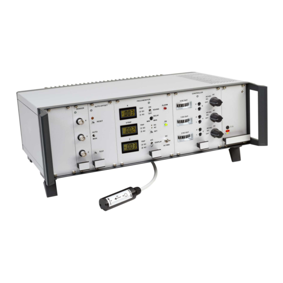
- Page 4 Introduction Fig. 1: Magnetic Field Compensation System MR-3 The magnetic field compensation system MR-3 has been designed for automatic triaxial compensation of magnetic field disturbances in the frequency range from 0 to 500 Hz. The system reduces slow disturbances, e. g. caused by trams, elevators or vehicles, as well as magnetic noise produced by power lines (typ.
- Page 5 Analog PI controllers control built-in power current sources which drive a suitable set of Helmholtz-type coils. The coils generate a compensation field which reduces the original field disturbances. The compensation coils are not part of the MR-3 system and must be provided by the user or service partner. Contact Stefan Mayer Instruments for a proposal for suitable compensation coils.
-
Page 6: Operation
Fig. 2: Definition of sensor measurement axes Instrument installation The MR-3 system can be used as bench-top instrument or can be mounted in 19- inch racks. In any case, there must be sufficient air flow through the instrument and the fins of the heat sinks for cooling. Never cover the ventilation slots of the lid, bottom, and side panels nor the heat sink at the rear side. -
Page 7: Sensor Module
4.3.1 Sensor module Fig. 3: Sensor module The sensor module carries the drive and detection electronics of the triaxial flux- gate magnetic field sensor. The magnetic field components X, Y, and Z are con- verted to proportional voltage signals which are present at the BNC connectors (1) in figure 3 on the module front. -
Page 8: Field Monitor Module
100 T per axis. It is used to suppress the constant portion of the earth’s magnetic field which is not compensated by the MR-3. The TEST button (4) can be used to check the system installation, see section 4.7. When the TEST button is pressed, the field settings of all three axes are simulta- neously changed by approximately +1 T each. -
Page 9: Controller Module
show the incremental DC magnetic field components (DC magnetic field less preset offset). In position AC (down) the displays show the true rms AC magnetic field components. The frequency range is 10 Hz to 1000 Hz. (5) SET push button. When this button is pushed, the Y digital display shows the preset trip level for the alarm function. -
Page 10: Rear Panel Summary
The controller module is the interface between the sensor signals and the power amplifiers at the rear side of the MR-3. The front contains the following elements: (1) DC current meters. These analog meters show the DC drive level of the power current sources which drive the compensation coils. -
Page 11: Electrical Connections
Electrical connections First, the sensor is connected to the sensor receptacle at the rear panel (fig. 7 c). The compensation coils for the X-, Y-, and Z-component must be connected to the supplied clamp connector which can then be plugged into the mating socket at the rear side (fig. -
Page 12: Operation Of The Controllers
40 T for correct operation of the system. The magnetic field compensation system MR-3 is suited for permanent operation. However, permanent overload conditions, which could reduce the lifetime of the current sources, should be avoided. The output currents can be read from the analog meters on the controller module (see (1) in fig. -
Page 13: Adjustment Of The Pi Controllers
coils with recommended impedance. Adjustment of the PI controllers Adjustment of the controllers is accomplished in the same way for each compo- nent X, Y, and Z by the following procedure: It is recommended to connect an oscilloscope to the analog output on the sensor module (BNC connector in fig. 3) of the respective component to be adjusted. -
Page 14: Alarm Function
Alarm function The MR-3 provides a visible and audible alarm signal which is activated when the magnetic field exceeds the preset values. The trip levels can be independently set for the AC rms and incremental DC magnetic field, but they are common for X, Y, and Z. - Page 15 Specifications Magnetic field sensor triaxial fluxgate sensor Zero drift 0.1 nT/K Noise 0.3 nT RMS (0.1 Hz 1000 Hz), 20 pT/ Hz @ f = 1 Hz Analog outputs 1 V/ T, BNC connectors for X, Y, Z Voltage range typ.
- Page 16 Conversion of Measurement Units Magnetic induction Unit 1 Tesla (1 T) 1 T = 10 Gauss = 1 kg s 1 T = 10 mG Magnetic field Unit 1 A/m 1 A/m = 4 Oersted Connection between for nonmagnetic environment Vacuum permeability m kg s Units:...
- Page 17 Warranty All components of the magnetic field compensation system MR-3 are warranted to be free from defects in material and workmanship for a period of two years from the date of delivery to purchaser. The guarantee will apply only if the instrument is operated in accordance with this instruction manual and if the instrument is not changed by the purchaser.
Need help?
Do you have a question about the MR-3 and is the answer not in the manual?
Questions and answers