Table of Contents
Advertisement
Quick Links
Advertisement
Table of Contents

Related Manuals for Stefan Mayer Instruments MK-1


Summary of Contents for Stefan Mayer Instruments MK-1
- Page 1 Single Axis Magnetic Field Compensation System User’s Manual valid for instruments with serial number 292 and higher with auto-reset function – January 2021 – Stefan Mayer Instruments GmbH & Co. KG Wallstr. 7, D-46535 Dinslaken, Germany Tel./Fax: +49 2064 479762/3...
-
Page 2: Table Of Contents
Contents 1 Safety precautions 2 Introduction 3 Main frame with power supply and current source 3.1 Description ....... 3.2 Specifications . -
Page 3: Safety Precautions
If the instrument is used in a manner not specified by the manufacturer, the protection provided by the instrument can be impaired. Stefan Mayer Instruments shall not be liable for any direct, indirect, special, incidental or consequential damages arising out of the use of its instruments. -
Page 4: Introduction
Introduction The MK-1 is a single axis magnetic field compensation system designed for image improvement in magnetic resonance imaging (MRI) and other applications where feedback magnetic field control systems are not suitable. The system reduces slow disturbances, e. g. caused by trams, elevators or vehicles, as well as magnetic noise produced by power lines by establishing a counteracting magnetic field with the... -
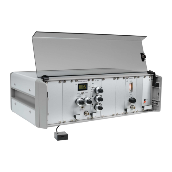
Page 5: Main Frame With Power Supply And Current Source
filter modules. The basic version contains one magnetometer and one filter module. It is possible to install up to three magnetometers and filters. Compensation coils are not part of the MK-1 and must be provided separately. The mains power connector and switch as well as connectors for sensors and com- pensation coils are located on the rear panel. -
Page 6: Specifications
Specifications Current source gain 0.5 A/V Output current max. 2.5 A Minimum load resistance 3.0 Ω Compliance at 2.5 A typ. Power supply built in, 115/230 V 10%, AC 50 to 60 Hz, max. 2.0 A Power cord ratings 250 VAC, 10A Operating temperature 0 to 40 C Dimensions of main frame enclosure... -
Page 7: Magnetometer Specifications
panel. If two or three magnetometer modules are installed, then they must not be interchanged. The digital display shows the DC magnetic field in T. The display range can be changed between 19.99 T and 199.9 T with the switch RANGE. The magnetometer is zeroed by pressing the RESET button. -
Page 8: Filter Module
Filter module Description The filter module provides analog filtering of the magnetometer output signal. It contains two parallel band-pass filter sections for 16.7 Hz (or 60 Hz, depending on version) and 50 Hz, a DC channel, and a summing amplifier. The output signals of the individual filter sections can be switched separately and with selectable polarity to the input of the summing amplifier. -
Page 9: Operation And Adjustment
Operation and adjustment Before the instrument is switched on with the rear side power switch, the sen- sor(s) and compensation coils must be properly installed and connected to the corresponding receptacles. Turn the rotary gain switch on the amplifier front to position 0. -
Page 10: Conversion Of Measurement Units
Conversion of Measurement Units Magnetic induction Unit 1 Tesla (1 T) 1 T = 10 Gauss = 1 kg s 1 T = 10 mG Magnetic field strength Unit 1 A/m 1 A/m = 4 Oersted Connection between for non-magnetic environment Vacuum permeability m kg s Units:...
Need help?
Do you have a question about the MK-1 and is the answer not in the manual?
Questions and answers