
Related Manuals for AnaPico APPH40G


Summary of Contents for AnaPico APPH40G
- Page 1 User Manual Signal Source Analyzer APPH6040, APPH20G, APPH40G User’s Manual – Signal Source Analyzers – v3.0 May 2019 AnaPico Ltd. - www.anapico.com – sales@anapico.com...
- Page 2 COPYRIGHT This manual is copyright by AnaPico Ltd. of Switzerland and all rights are reserved. No portion of this document may be reproduced, copied, transmitted, transcribed, stored in a retrieval system, or translated in any form or by any means.
-
Page 3: Table Of Contents
Direct Connectivity to Host via Ethernet Cable (no Router) ................ 16 Connecting through USB ..........................16 Connecting through GPIB ..........................16 Using the SCPI Application Programming Interface (API) ................16 Page 2 – Signal Source Analyzers – v3.0 May 2019 AnaPico Ltd. - www.anapico.com – sales@anapico.com... - Page 4 Measurement Procedure ..........................34 FFT A ..........................35 NALYZER EASUREMENT ..............................37 TABILITY ............................. 37 PECTRUM NALYSIS VCO C ............................38 HARACTERIZATION Measurement Procedure ..........................39 Page 3 – Signal Source Analyzers – v3.0 May 2019 AnaPico Ltd. - www.anapico.com – sales@anapico.com...
- Page 5 MAINTENANCE AND WARRANTY INFORMATION....................42 ..........................42 DJUSTMENTS AND ALIBRATION ................................42 EPAIR ............................. 42 ARRANTY NFORMATION ............................42 QUIPMENT ETURNS APPENDIX A ................................43 Page 4 – Signal Source Analyzers – v3.0 May 2019 AnaPico Ltd. - www.anapico.com – sales@anapico.com...
-
Page 6: General Remarks
The instrument may only be connected to a network or a computer by using a shielded LAN or USB cable. Unless shorter lengths are prescribed, a maximum length of 3 m must not be exceeded for the LAN and the USB connection. Page 5 – Signal Source Analyzers – v3.0 May 2019 AnaPico Ltd. - www.anapico.com – sales@anapico.com... -
Page 7: Signal Connections
Transportation The instruments must only be transported with the packaging supplied by the manufacturer. The instrument can be lifted or transported in any orientation. Page 6 – Signal Source Analyzers – v3.0 May 2019 AnaPico Ltd. - www.anapico.com – sales@anapico.com... -
Page 8: Safety Information
Earth (Ground) EU label for separate collection of electrical and electronic waste. Caution, general danger zone. Attend the manual and/or a notice on the device. Page 7 – Signal Source Analyzers – v3.0 May 2019 AnaPico Ltd. - www.anapico.com – sales@anapico.com... -
Page 9: General Safety Considerations
For this reason, the product may only be disassembled or opened by specially trained personnel. Improper disassembly may be hazardous to your health. National waste disposal regulations must be observed. Page 8 – Signal Source Analyzers – v3.0 May 2019 AnaPico Ltd. - www.anapico.com – sales@anapico.com... -
Page 10: Technical Specifications
Dimensions of the 3U benchtop case: A = 467mm B = 153mm C = 518mm D = 341mm E = 400mm Weight: 10 kg Page 9 – Signal Source Analyzers – v3.0 May 2019 AnaPico Ltd. - www.anapico.com – sales@anapico.com... -
Page 11: Connectors
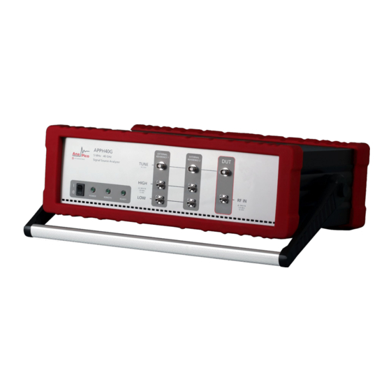
DUT RF IN port This female SMA or 2.92 mm connector is the DUT signal input. It is AC- coupled and has an impedance of 50 ohms. Page 10 – Signal Source Analyzers – v3.0 May 2019 AnaPico Ltd. - www.anapico.com – sales@anapico.com... -
Page 12: Rear Panel
This female BNC connector is the external trigger input (TTL). The maximum allowed DC level is 12 V, and the trigger threshold is 1 V +/- 0.1 V. Page 11 – Signal Source Analyzers – v3.0 May 2019 AnaPico Ltd. - www.anapico.com – sales@anapico.com... -
Page 13: Minimum Distances
The minimum distances are: Minimum distance: A: 150 mm Page 12 – Signal Source Analyzers – v3.0 May 2019 AnaPico Ltd. - www.anapico.com – sales@anapico.com... -
Page 14: Energizing And De-Energizing
Environmental Information Waste electrical and electronic equipment must not be disposed of with unsorted municipal waste but must be collected separately. Contact the AnaPico customer service center for environmentally responsible disposal of the product. Specially marked equipment has a battery or accumulator that must not be disposed of with unsorted municipal waste but must be collected separately. -
Page 15: Introduction
Introduction This instruction manual is valid for the AnaPico model series APPH. The following chapters give guidance for a quick and easy setup and use of your new instrument. General Features and Functions (Model Overview) AnaPico Signal Source Analyzer model overview... -
Page 16: Getting Started
LED marked READY will start to flash briefly. This indicates that the machine performs a self- test. Once the READY LED is static on, the instrument is ready for operation. Page 15 – Signal Source Analyzers – v3.0 May 2019 AnaPico Ltd. - www.anapico.com – sales@anapico.com... -
Page 17: Connecting To Lan Via Dhcp Router
Installing the APPH Graphical User Interface (APPH GUI) AnaPico's graphical user interface (APPH GUI) provides an intuitive control of the APPH. The Java based application runs under any operating system, including Windows XP, Vista, 7, 8 and 10 with standard requirements. -
Page 18: Troubleshooting The Lan Interconnection
To install the GUI on the computer, insert the APPH Software and Manual CD into the CD/DVD drive or download the latest GUI setup file from the AnaPico website. If the setup doesn't start automatically, double click on the setup.exe to run the installer. -
Page 19: Serial Number
Each instrument is manufactured with a unique serial number shown on the sticker on the rear panel. This serial number is also internally stored and determines the instrument configuration and guides the software accordingly. Page 18 – Signal Source Analyzers – v3.0 May 2019 AnaPico Ltd. - www.anapico.com – sales@anapico.com... -
Page 20: Using The Graphical User Interface (Gui)
Below the tab selection, the measurement area is shown. This area looks different based on the selected measurement mode. In general, configurations are grouped within areas with a blue title. Page 19 – Signal Source Analyzers – v3.0 May 2019 AnaPico Ltd. - www.anapico.com – sales@anapico.com... -
Page 21: Menu Bar
The configuration of a spec line can be seen below. The data can be input manually in table format on the left or by clicking and dragging in the plot on the right. Spec lines can be saved and loaded. Page 20 – Signal Source Analyzers – v3.0 May 2019 AnaPico Ltd. - www.anapico.com – sales@anapico.com... -
Page 22: Measurement Tabs (Modes)
To view information about the APPH GUI itself, the help menu can be used. It also offers the possibility to log a session or some interaction in an ecrypted way for support purposes. Activating this option will slow down performance significantly so it is only adviced to to so when instructed by Anapico support staff. Update Button If the computer is connected to the internet, it will check for a new version on startup. -
Page 23: Mode: Absolute Phase Noise Measurement
Figure 6 shows a measurement from 10 Hz to 100 MHz with 100 correlations with internal references and no voltage ports activated. Page 22 – Signal Source Analyzers – v3.0 May 2019 AnaPico Ltd. - www.anapico.com – sales@anapico.com... -
Page 24: Absolute Phase Noise Measurement Of A Continuous Wave (Cw) Signal
Time Domain tab of the measurement window. Note, the measurement time largely depends on the minimum offset frequency and the total number of correlations. Page 23 – Signal Source Analyzers – v3.0 May 2019 AnaPico Ltd. - www.anapico.com – sales@anapico.com... -
Page 25: Absolute Phase Noise Of A Pulsed Signal [Requires Option Pulse]
Figure 8 shows the completed measurement of a pulse modulated signal (in green). Page 24 – Signal Source Analyzers – v3.0 May 2019 AnaPico Ltd. - www.anapico.com – sales@anapico.com... -
Page 26: The Plot Window Tabs
The right plot shows the Allan deviation, calculated from the phase noise. The statistic tab always displays the information for the currently selected trace. Page 25 – Signal Source Analyzers – v3.0 May 2019 AnaPico Ltd. - www.anapico.com – sales@anapico.com... -
Page 27: List Of Traces
Ctrl key, while clicking. All traces will be deselected by clicking the “Unsel” button. Del: Selected traces can be removed from the trace list by clicking on Del button, or by pressing the Delete key. Page 26 – Signal Source Analyzers – v3.0 May 2019 AnaPico Ltd. - www.anapico.com – sales@anapico.com... -
Page 28: Plot Windows
The statistics window shows statistical parameters of the currently selected trace, such as jitter, residual FM, or integral phase noise. The integration range for the calculations can be adjusted in this window. Page 27 – Signal Source Analyzers – v3.0 May 2019 AnaPico Ltd. - www.anapico.com – sales@anapico.com... -
Page 29: Saving And Loading Traces
0.1 Hz 1250 1500 1750 2150 1000 1250 1500 1900 1 Hz 10 Hz 1000 1250 1650 100 Hz 1000 1400 1 kHz 1150 Page 28 – Signal Source Analyzers – v3.0 May 2019 AnaPico Ltd. - www.anapico.com – sales@anapico.com... -
Page 30: Measurement Time (Using Gui)
Start Frequency [Hz] Measurement Time [s] 0.01 Hz 0.1 Hz 1 Hz 10 Hz 100 Hz 1 kHz 10 kHz Typical measurement times for APPH Page 29 – Signal Source Analyzers – v3.0 May 2019 AnaPico Ltd. - www.anapico.com – sales@anapico.com... -
Page 31: Additive Phase Noise Measurement
1) The phase detector constant is determined automatically during signal detection. The measurement button turns green and reads “Calibrate”. It also displays the phase detector constant Kphi. Page 30 – Signal Source Analyzers – v3.0 May 2019 AnaPico Ltd. - www.anapico.com – sales@anapico.com... -
Page 32: Additive Phase Noise Of A Pulsed Signal (With Option Pulse Only)
(see Figure 12). Figure 12 Pulse modulation specific input controls in the additive phase noise tab. Page 31 – Signal Source Analyzers – v3.0 May 2019 AnaPico Ltd. - www.anapico.com – sales@anapico.com... -
Page 33: Amplitude Noise Measurement
Page 32 – Signal Source Analyzers – v3.0 May 2019 AnaPico Ltd. - www.anapico.com – sales@anapico.com... -
Page 34: Measurement Procedure
The transient analyzer tab provides frequency, phase, and amplitude versus time measurements. The sampling period can be chosen down to 16 ns, allowing the user to look at fast frequency transients and modulations. Page 33 – Signal Source Analyzers – v3.0 May 2019 AnaPico Ltd. - www.anapico.com – sales@anapico.com... -
Page 35: Measurement Procedure
Connect your signal generator to the DUT input connector of the APPH. Choose the parameters to be measured by activating the corresponding check boxes on the right side of the GUI. Page 34 – Signal Source Analyzers – v3.0 May 2019 AnaPico Ltd. - www.anapico.com – sales@anapico.com... -
Page 36: Fft Analyzer Measurement
BASEBAND 1 and BASEBAND 2. For a single channel measurement, only BASEBAND 1 is required. Select the frequency offset range and the number of averages and correlations. Page 35 – Signal Source Analyzers – v3.0 May 2019 AnaPico Ltd. - www.anapico.com – sales@anapico.com... - Page 37 Select either “Single Channel” or “Two channel cross-correlated” measurement. Press the Measure button to run the measurement. Figure 17 FFT analyzer mode Page 36 – Signal Source Analyzers – v3.0 May 2019 AnaPico Ltd. - www.anapico.com – sales@anapico.com...
-
Page 38: Time Stability
Once triggered, the measurement will run constantly and will repeat when the configured number of iterations is reached. There are four markers provided, each with its own delta marker. They can be activated individually. Page 37 – Signal Source Analyzers – v3.0 May 2019 AnaPico Ltd. - www.anapico.com – sales@anapico.com... -
Page 39: Vco Characterization
The VCO characterization tab provides the ability to fully characterize a voltage-controlled oscillator (VCO or VCXO), including Kvco, current draw, power output, pushing and spot phase noise over a specified control voltage range. Figure 20 VCO characterization tab. Page 38 – Signal Source Analyzers – v3.0 May 2019 AnaPico Ltd. - www.anapico.com – sales@anapico.com... -
Page 40: Measurement Procedure
The results region will show additional information about the measured traces. The marker region allows to configure markers. Markers can either be set to a specific voltage or frequency. Page 39 – Signal Source Analyzers – v3.0 May 2019 AnaPico Ltd. - www.anapico.com – sales@anapico.com... - Page 41 LAN client. Once the computer is configured for a LAN client, you can use the VXI-11 protocol and the VISA library to send SCPI commands to the signal generator over the LAN interface. Example programs are available by request to support@AnaPico.com. Page 40 – Signal Source Analyzers – v3.0 May 2019 AnaPico Ltd. - www.anapico.com – sales@anapico.com...
- Page 42 GPIB connector, the talker/listener GPIB address of the APPH requires setting. The default GPIB address of the APPH is 1. Please see the APPH Programmer’s Manual for detailed description of supported SCPI commands. Page 41 – Signal Source Analyzers – v3.0 May 2019 AnaPico Ltd. - www.anapico.com – sales@anapico.com...
- Page 43 All AnaPico instruments are warranted against defects in material and workmanship for a period of two years from the date of shipment. AnaPico will, at its option, repair or replace products that prove to be defective during the warranty period, provided they are returned to AnaPico and provided the preventative maintenance procedures are followed.
- Page 44 Appendix A Page 43 – Signal Source Analyzers – v3.0 May 2019 AnaPico Ltd. - www.anapico.com – sales@anapico.com...
- Page 45 AnaPico Ltd. of Switzerland Phone +41 44 515 55 01 www.anapico.com Europastrasse 9 +41 44 440 00 50 www.anapico.com/downloads/ 8152 Glattbrugg Email sales@anapico.com Switzerland Page 44 – Signal Source Analyzers – v3.0 May 2019 AnaPico Ltd. - www.anapico.com – sales@anapico.com...
- Page 46 NOTES Page 45 – Signal Source Analyzers – v3.0 May 2019 AnaPico Ltd. - www.anapico.com – sales@anapico.com...
Need help?
Do you have a question about the APPH40G and is the answer not in the manual?
Questions and answers